
Subscribe to Our Youtube Channel
Related Manuals for Beckhoff EP4374


Summary of Contents for Beckhoff EP4374
- Page 1 Documentation EP4374 EtherCAT Box with analog inputs and outputs Version: Date: 2019-07-15...
-
Page 3: Table Of Contents
Standard objects (0x1000-0x1FFF) ................. 40 4.4.4 Profile-specific objects (0x6000-0xFFFF) ................ 45 Restoring the delivery state ...................... 48 5 Appendix .............................. 49 General operating conditions...................... 49 General note on the introduction of the Beckhoff Identification Code (BIC) ........ 50 Support and Service ........................ 52 EP4374 Version: 2.3... - Page 4 Table of contents Version: 2.3 EP4374...
-
Page 5: Foreword
All the components are supplied in particular hardware and software configurations appropriate for the application. Modifications to hardware or software configurations other than those described in the documentation are not permitted, and nullify the liability of Beckhoff Automation GmbH & Co. KG. Personnel qualification This description is only intended for trained specialists in control, automation and drive engineering who are familiar with the applicable national standards. -
Page 6: Notes On The Documentation
EP1590927, EP1789857, EP1456722, EP2137893, DE102015105702 with corresponding applications or registrations in various other countries. ® EtherCAT is registered trademark and patented technology, licensed by Beckhoff Automation GmbH, Germany. Copyright © Beckhoff Automation GmbH & Co. KG, Germany. The reproduction, distribution and utilization of this document as well as the communication of its contents to others without express authorization are prohibited. -
Page 7: Documentation Issue Status
HH - hardware version 01 - hardware version 01 Beckhoff Identification Code (BIC) The Beckhoff Identification Code contains additional information about the delivery state of the module: General note on the introduction of the Beckhoff Identification Code (BIC) [} 50]. EP4374... -
Page 8: Product Overview
EtherCAT communication and for the power supply: • Feed • Downstream connection This enables the cabling of EtherCAT Box modules in a line structure: EtherCAT Power Fig. 1: EtherCAT Box modules: Example of cabling in a line structure Version: 2.3 EP4374... -
Page 9: Ep4374 - Introduction
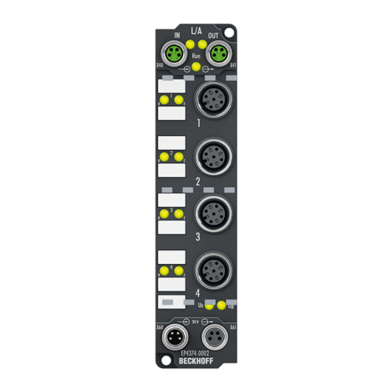
EP4374 - Introduction Fig. 2: EP4374-0002 EtherCAT Box with analog inputs and outputs EP4374-0002 has two analog inputs and two analog outputs. The signal range can be individually parameterized for each analog input and output: • -10 .. +10 V • 0 .. 10 V •... -
Page 10: Technical Data
Product overview Technical data Technical data EP4374-0002 Fieldbus Fieldbus EtherCAT Connection 2 x M8 socket, green Electrical isolation 500 V (fieldbus / IO) Process image Inputs: 2 x 16 bit Outputs: 2 x 16 bit Supply Connection Feed: 1 x M8 plug, 4-pin Downstream connection: 1 x M8 socket, 4-pin Current carrying capacity of the connections... - Page 11 Product overview Technical data EP4374-0002 Mechanics Weight approx. 165 g Mounting position variable Approvals and conformity Approvals CE, cURus [} 24], ATEX [} 25] Analog inputs The signal range can be switched during operation. The following table shows the electrical specifications depending on the selected signal range.
-
Page 12: Scope Of Supply
Scope of supply Make sure that the following components are included in the scope of delivery: • 1x EP4374-0002 EtherCAT Box • 2x protective cap for EtherCAT socket, M8, green (pre-assembled) • 1x protective cap for supply voltage input, M8, transparent (pre-assembled) •... -
Page 13: Process Image
The data of the second analog channel have the same structure as those of the first channel. AO Outputs Channel 3 The data for the third analog channel can be found under AO Outputs Channel 3. AO Outputs Channel 4 The data of the forth analog channel have the same structure as those of the third channel. EP4374 Version: 2.3... -
Page 14: Mounting And Cabling
Ø 3.5 mm for M3 Metal parts brass, nickel-plated Contacts CuZn, gold-plated Power feed through max. 4 A Mounting position variable Protection class IP65, IP66, IP67 (conforms to EN 60529) when screwed together Dimensions (H x W x D) approx. 126 x 30 x 26.5 mm Version: 2.3 EP4374... -
Page 15: Fixing
Protection class IP67 can only be guaranteed if all cables and connectors are connected. Protect the connections against soiling during mounting. Mount the module with two M3 screws on the fastening holes in the corners of the module. The fastening holes have no thread. EP4374 Version: 2.3... -
Page 16: Cabling
Guidelines Follow these guidelines to ensure IP67 protection: • Mount plugs with the torque values specified below. Use a torque wrench, e.g. Beckhoff ZB8801. • Seal unused connectors with protective caps. • Ensure the correct seating of pre-assembled protective caps. -
Page 17: Power Supply
• OUT: right M8 connector for forwarding the supply voltages Fig. 5: Connections for power supply Pin assignment Fig. 6: M8 connector Voltage Core colors Control voltage U Brown Peripheral voltage U White Blue Black The core colors apply to Beckhoff ZK2020-xxxx-xxxx cables EP4374 Version: 2.3... -
Page 18: Fig. 7 Status Leds For The Power Supply
Fig. 7: Status LEDs for the power supply Display Meaning (control voltage) Supply voltage, U , is not present green illuminated Supply voltage, U , is present (peripheral voltage) Supply voltage, U , is not present green illuminated Supply voltage, U , is present Version: 2.3 EP4374... -
Page 19: Fig. 8 Power Cable Conductor Losses
8 m power cable with 0.34 mm² cross-section has a voltage drop of 3.2 V at 4 A. EP92x4 Power Distribution Modules With EP9214 and EP9224 Power Distribution Modules intelligent concepts for voltage supply are available. Further information may be found under www.beckhoff.com/EP9224. EP4374 Version: 2.3... -
Page 20: Ethercat
(CAT5) according to EN 50173 or ISO/IEC 11801 should be used. EtherCAT uses four wires for signal transmission. Thanks to automatic line detection ("Auto MDI-X"), both symmetrical (1:1) or cross-over cables can be used between Beckhoff EtherCAT. Detailed recommendations for the cabling of EtherCAT devices can be found at https://infosys.beckhoff.com/content/1033/ethernetcabling/index.html?id=1661412216745722148. -
Page 21: Fig. 11 Ethercat Status Leds
Meaning Slave is in "Init" state flashes uniformly Slave is in "Pre-Operational“ state flashes sporadically Slave is in "Safe-Operational" state Slave is in "Operational" state A description of the EtherCAT slave states can be found under https://infosys.beckhoff.com/content/1033/ethercatsystem/1036980875.html?id=8582353789396071752. EP4374 Version: 2.3... -
Page 22: Analog Interfaces
Correct function is indicated if the green Run LED is on and the red Error LED is off. Status LEDs at M12 connections 3 and 4 (outputs) Connection Display Meaning M12 socket no. 3 and 4 No data transfer to the D/A converter left green Data transfer to the D/A converter Version: 2.3 EP4374... -
Page 23: Fig. 14 Signal Connection - Analog Inputs
The sensor is connected via In+ and In-. The sensor can optionally be operated/supplied with 24 V Analog outputs Fig. 15: Signal connection - Analog outputs The actuator is connected via output +/- and output GND. The actuator can optionally be operated/supplied with 24 V EP4374 Version: 2.3... -
Page 24: Ul Requirements
To meet the UL requirements, EtherCAT Box Modules has to be operated only at an ambient temperature range of 0 to 55°C! Marking for UL All EtherCAT Box Modules certified by UL (Underwriters Laboratories) are marked with the following label. Fig. 16: UL label Version: 2.3 EP4374... -
Page 25: Atex Notes
FF - firmware version HH - hardware version Example with batch number 29 10 02 01: 29 - week of production 29 10 - year of production 2010 02 - firmware version 02 01 - hardware version 01 EP4374 Version: 2.3... -
Page 26: Bg2000 - Ethercat Box Protection Enclosures
EtherCAT Box. Installation Put the cables for EtherCAT, power supply and sensors/actuators through the hole of the protection enclosure. Fig. 17: BG2000 - putting the cables Fix the wires for EtherCAT, power supply and sensors/actuators to the EtherCAT Box. Version: 2.3 EP4374... -
Page 27: Atex Documentation
Notes about operation of EtherCAT Box Modules (EPxxxx-xxxx) in potentially explo- sive areas (ATEX) Pay also attention to the continuative documentationNotes about operation of EtherCAT Box Mod- ules (EPxxxx-xxxx) in potentially explosive areas (ATEX) that is available in the download area of the Beckhoff homepage http:\\www.beckhoff.com! EP4374 Version: 2.3... -
Page 28: Commissioning And Configuration
F800:04 TwinCAT Proceed as follows to change the signal range of an analog channel in TwinCAT: 1. Double-click the IO module EP4374-0002 in the IO tree. 2. Click on the "CoE - Online" tab. ð The CoE directory is displayed 3. -
Page 29: Object Overview
EtherCAT XML Device Description The display matches that of the CoE objects from the EtherCAT XML Device Description. We rec- ommend downloading the latest XML file from the download area of the Beckhoff website and in- stalling it according to installation instructions. - Page 30 0x00001388 (5000 1C32:08 Command 0x0000 (0 1C32:09 Maximum delay time 0x00001388 (5000 1C32:0B SM event missed counter 0x0000 (0 1C32:0C Cycle exceeded counter 0x0000 (0 1C32:0D Shift too short counter 0x0000 (0 1C32:20 Sync error 0x00 (0 Version: 2.3 EP4374...
- Page 31 6010:02 Overrange 0x00 (0 6010:03 Limit 1 0x00 (0 6010:05 Limit 2 0x00 (0 6010:07 Error 0x00 (0 6010:0E Sync error 0x00 (0 6010:0F TxPDO State 0x00 (0 6010:10 TxPDO Toggle 0x00 (0 6010:11 Value 0x0000 (0 EP4374 Version: 2.3...
- Page 32 User scale offset 0x0000 (0 8010:12 User scale gain 0x00010000 (65536 8010:13 Limit 1 0x0000 (0 8010:14 Limit 2 0x0000 (0 8010:15 Filter settings 0x0000 (0 8010:17 User calibration offset 0x0000 (0 8010:18 User calibration gain 0x4000 (16384 Version: 2.3 EP4374...
- Page 33 [} 46] 802F:01 R0 Calibration Offset 0x0000 (0 802F:02 R0 Calibration Gain 0x4000 (16384 802F:03 R1 Calibration Offset 0x0000 (0 802F:04 R1 Calibration Gain 0x4000 (16384 802F:05 R2 Calibration Offset 0x0000 (0 802F:06 R2 Calibration Gain 0x4000 (16384 EP4374 Version: 2.3...
- Page 34 Input type Ch2 0x0000 (0 F800:03 Output type Ch3 0x0000 (0 F800:04 Output type Ch4 0x0000 (0 Legend Flags: RO (Read Only): this object can be read only RW (Read/Write): this object can be read and written to Version: 2.3 EP4374...
-
Page 35: Object Description And Parameterization
EtherCAT XML Device Description The display matches that of the CoE objects from the EtherCAT XML Device Description. We rec- ommend downloading the latest XML file from the download area of the Beckhoff website and in- stalling it according to installation instructions. - Page 36 60 Hz FIR IIR 1 IIR 2 IIR 3 IIR 4 IIR 5 IIR 6 IIR 71 IIR 8 8000:17 User calibration offset User calibration: Offset INT16 0x0000 (0 8000:18 User calibration gain User calibration: Gain INT16 0x4000 (16384 Version: 2.3 EP4374...
- Page 37 60 Hz FIR IIR 1 IIR 2 IIR 3 IIR 4 IIR 5 IIR 6 IIR 71 IIR 8 8010:17 User calibration offset User calibration: Offset INT16 0x0000 (0 8010:18 User calibration gain User calibration: Gain INT16 0x4000 (16384 EP4374 Version: 2.3...
- Page 38 327 ms (32767/100) for the output value to change from the maximum value (32767) to the default value in the event of a fault. 8020:15 User calibration offset User calibration: Offset INT16 0x0000 (0 8020:16 User calibration gain User calibration: Gain UINT16 0x4000 (16384 Version: 2.3 EP4374...
- Page 39 Input signal range for channel 2 (values see channel 1) UINT16 0x0000 (0 F800:03 Output type Ch3 Output signal range for channel 3 UINT16 0x0000 (0 -10…+10 V 0...20 mA 4...20 mA 0...10 V F800:04 Output type Ch4 Output signal range for channel 4 (values see channel 3) UINT16 0x0000 (0 EP4374 Version: 2.3...
-
Page 40: Objects For Regular Operation
Commissioning and configuration 4.4.2 Objects for regular operation The EP4374 has no such objects. 4.4.3 Standard objects (0x1000-0x1FFF) The standard objects have the same meaning for all EtherCAT slaves. Index 1000 Device type Index (hex) Name Meaning Data type Flags... - Page 41 0x0F (TxPDO State)) 1A00:0A SubIndex 010 10. PDO Mapping entry (object 0x6000 (AI Inputs), entry UINT32 0x6000:10, 1 0x10 (TxPDO Toggle)) 1A00:0B SubIndex 011 11. PDO Mapping entry (object 0x6000 (AI Inputs), entry UINT32 0x6000:11, 16 0x11 (Value)) EP4374 Version: 2.3...
- Page 42 0x02 (2 1C12:01 Subindex 001 1st allocated RxPDO (contains the index of the associ- UINT16 0x1600 ated RxPDO mapping object) (5632 1C12:02 Subindex 002 2nd allocated RxPDO (contains the index of the associ- UINT16 0x1601 ated RxPDO mapping object) (5633 Version: 2.3 EP4374...
- Page 43 0x0000 (0 1C32:09 Maximum delay time UINT32 0x00001388 (5000 1C32:0B SM event missed UINT16 0x0000 (0 counter 1C32:0C Cycle exceeded UINT16 0x0000 (0 counter 1C32:0D Shift too short counter UINT16 0x0000 (0 1C32:20 Sync error BOOLEAN 0x00 (0 EP4374 Version: 2.3...
- Page 44 1C33:0B SM event missed as 0x1C32:11 UINT16 0x0000 (0 counter 1C33:0C Cycle exceeded as 0x1C32:12 UINT16 0x0000 (0 counter 1C33:0D Shift too short counter as 0x1C32:13 UINT16 0x0000 (0 1C33:20 Sync error as 0x1C32:32 BOOLEAN 0x00 (0 Version: 2.3 EP4374...
-
Page 45: Profile-Specific Objects (0X6000-0Xffff)
Analog output Analog output data INT16 0x0000 (0 Index 800E AI Internal data Ch.1 Index (hex) Name Meaning Data type Flags Default 800E:0 AI Internal data Ch.1 UINT8 0x01 (1 800E:01 ADC raw value INT16 0x0000 (0 EP4374 Version: 2.3... - Page 46 0x4000 (16384 Index 803E AO Internal data Ch.4 Index (hex) Name Meaning Data type Flags Default 803E:0 AO Internal data Ch.4 UINT8 0x01 (1 803E:01 DAC raw value This is the raw DAC value. UINT16 0x0000 (0 Version: 2.3 EP4374...
- Page 47 Index (hex) Name Meaning Data type Flags Default F010:0 Module list UINT8 0x04 (4 F010:01 SubIndex 001 UINT32 0x0000012C (300 F010:02 SubIndex 002 UINT32 0x0000012C (300 F010:03 SubIndex 003 UINT32 0x00000190 (400 F010:04 SubIndex 004 UINT32 0x00000190 (400 EP4374 Version: 2.3...
-
Page 48: Restoring The Delivery State
Fig. 21: Entering a restore value in the Set Value dialog Alternative restore value In some older terminals / boxes the backup objects can be switched with an alternative restore value: Decimal value: 1819238756 Hexadecimal value: 0x6C6F6164 An incorrect entry for the restore value has no effect. Version: 2.3 EP4374... -
Page 49: Appendix
(ph-Value > 12) > 40°C: not resistant Acetic acid not resistant Argon (technical clean) resistant • resistant: Lifetime several months • non inherently resistant: Lifetime several weeks • not resistant: Lifetime several hours resp. early decomposition EP4374 Version: 2.3... -
Page 50: General Note On The Introduction Of The Beckhoff Identification Code (Bic)
Identification Code (BIC) General In future you will increasingly find machine-readable information on Beckhoff products in the form of a Data Matrix Code (DMC, ECC200). This helps us to improve the quality assurance process, beyond which you can use it for better identification of our products. - Page 51 Article description Quantity An important component of the BIC is the Beckhoff Traceability Number (BTN, item no. 2). The BTN is a unique 8-character serial number that in future will replace all other serial number systems at Beckhoff (e.g. batch designations on IO components, hitherto serial number circle for safety products, etc.). The BTN is likewise being introduced gradually, so it may be the case that the BTN is not yet coded in the BIC.
-
Page 52: Support And Service
Beckhoff's branch offices and representatives Please contact your Beckhoff branch office or representative for local support and service on Beckhoff products! The addresses of Beckhoff's branch offices and representatives round the world can be found on her internet pages: http://www.beckhoff.com You will also find further documentation for Beckhoff components there. - Page 53 List of illustrations List of illustrations Fig. 1 EtherCAT Box modules: Example of cabling in a line structure ..........Fig. 2 EP4374-0002..........................Fig. 3 Dimensions ..........................Fig. 4 Connector overview ........................Fig. 5 Connections for power supply ..................... Fig. 6 M8 connector ..........................
Need help?
Do you have a question about the EP4374 and is the answer not in the manual?
Questions and answers