
Related Manuals for Beckhoff EP1518-0001


Summary of Contents for Beckhoff EP1518-0001
- Page 1 Documentation EP1518-0002 EtherCAT Box with 8 digital inputs and 2 counters Version: 2.1.0 Date: 2018-12-05...
-
Page 3: Table Of Contents
Table of contents Table of contents 1 Foreword .............................. 5 Notes on the documentation...................... 5 Safety instructions .......................... 6 Documentation Issue Status...................... 7 2 Product overview............................ 8 EtherCAT Box - Introduction...................... 8 EP1518 - Introduction ........................ 10 EP1518 - Technical data ......................... 11 EP1518 – Process image ........................ 12 3 Installation.............................. 14 Mounting ............................ 14 3.1.1... - Page 4 Table of contents General operating conditions...................... 69 EtherCAT Box- / EtherCAT P Box - Accessories ................ 70 Support and Service ........................ 71 Version: 2.1.0 EP1518-0002...
-
Page 5: Foreword
The TwinCAT Technology is covered, including but not limited to the following patent applications and patents: EP0851348, US6167425 with corresponding applications or registrations in various other countries. ® EtherCAT is registered trademark and patented technology, licensed by Beckhoff Automation GmbH, Germany. Copyright © Beckhoff Automation GmbH & Co. KG, Germany. -
Page 6: Safety Instructions
All the components are supplied in particular hardware and software configurations appropriate for the application. Modifications to hardware or software configurations other than those described in the documentation are not permitted, and nullify the liability of Beckhoff Automation GmbH & Co. KG. Personnel qualification This description is only intended for trained specialists in control, automation and drive engineering who are familiar with the applicable national standards. -
Page 7: Documentation Issue Status
Foreword Documentation Issue Status Version Comment 2.1.0 • Update Safety instructions • Correction chapter Power cable • Update chapter Mounting 2.0.0 • Migration • Basic function principles chapter corrected 1.1.0 • Power Connection updated 1.0.0 • First release Firmware and hardware versions This documentation refers to the firmware and hardware version that was applicable at the time the documentation was written. -
Page 8: Product Overview
Product overview Product overview EtherCAT Box - Introduction The EtherCAT system has been extended with EtherCAT Box modules with protection class IP 67. Through the integrated EtherCAT interface the modules can be connected directly to an EtherCAT network without an additional Coupler Box. The high-performance of EtherCAT is thus maintained into each module. The extremely low dimensions of only 126 x 30 x 26.5 mm (h x w x d) are identical to those of the Fieldbus Box extension modules. -
Page 9: Fig. 2 Ethercat Box With M8 Connections For Sensors/Actuators
EtherCAT, which is available for download from our website (www.beckhoff.com) under Downloads. EtherCAT XML Device Description You will find XML files (XML Device Description Files) for Beckhoff EtherCAT modules on our web- site (www.beckhoff.com) under Downloads, in the Configuration Files area. -
Page 10: Ep1518 - Introduction
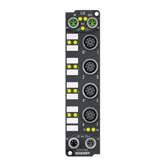
Product overview EP1518 - Introduction Fig. 4: EP1518-0001 and EP1518-0002 8 digital inputs (24 V ), 2 counters The EP1518-0002 EtherCAT Box with digital inputs acquires binary control signals from the process level and transfers them, with electrical isolation, to the controller. -
Page 11: Ep1518 - Technical Data
Product overview EP1518 - Technical data Technical data EP1518-0001 EP1518-0002 Fieldbus EtherCAT Fieldbus connection 2 x M8 socket (green) Number of inputs 8, 2 of which can be used as 32-bit up/down counters Input connections [} 27] Nominal input voltage 24 V... -
Page 12: Ep1518 - Process Image
Product overview EP1518 – Process image The process image depends on the selected operation mode [} 49]. Operation mode: 2 counters and 2 digital inputs (delivery state) The input data of the 1st counter can be found under CNT Input Channel 1. The adoption of the Set counter bit from CNT Output Channel 1 is displayed with Set counter done. - Page 13 Product overview Operation mode: 1 counter and 5 digital inputs The input data of the 1st counter can be found under CNT Input Channel 1. The adoption of the Set counter bit from CNT Output Channel 1 is displayed with Set counter done. The adoption of the Inhibit counter bit from CNT Output Channel 1 is displayed with Counter inhibited.
-
Page 14: Installation
Installation Installation Mounting 3.1.1 Dimensions Fig. 5: Dimensions of the EtherCAT Box Modules All dimensions are given in millimeters. Housing properties EtherCAT Box lean body wide bodies Housing material PA6 (polyamide) Casting compound Polyurethane Mounting two fastening holes Ø 3 mm for M3 two fastening holes Ø 3 mm for M3 two fastening holes Ø 4.5 mm for M4 Metal parts... -
Page 15: Fixing
Installation 3.1.2 Fixing Note or pointer While mounting the modules, protect all connectors, especially the IP-Link, against contamination! Only with connected cables or plugs the protection class IP67 is guaranteed! Unused connectors have to be protected with the right plugs! See for plug sets in the catalogue. Modules with narrow housing are mounted with two M3 bolts. -
Page 16: Nut Torque For Connectors
Installation 3.1.3 Nut torque for connectors M8 connectors It is recommended to pull the M8 connectors tight with a nut torque of 0.4 Nm. When using the torque control screwdriver ZB8800 is also a max. torque of 0.5 Nm permissible. Fig. 7: EtherCAT Box with M8 connectors M12 connectors It is recommended to pull the M12 connectors tight with a nut torque of 0.6 Nm. -
Page 17: Fig. 9 7/8" Plug Connectors
We recommend fastening the 7/8" plug connectors with a torque of 1.5 Nm. Fig. 9: 7/8" plug connectors Torque socket wrenches Fig. 10: ZB8801 torque socket wrench Ensure the right torque Use the torque socket wrenches available by Beckhoff to pull the connectors tight (ZB8800, ZB8801-0000)! EP1518-0002 Version: 2.1.0... -
Page 18: Connection
Installation Connection 3.2.1 EtherCAT connection For the incoming and ongoing EtherCAT connection, • the EtherCAT Box (EPxxxx) has two M8 sockets, marked in green • the Coupler Box (FBB-x110) has two M12 sockets Fig. 11: EtherCAT Box: M8, 30 mm housing Fig. 12: EtherCAT Box: M860 mm housing (example: EP9214) Fig. 13: Coupler Box: M12 Assignment There are various different standards for the assignment and colors of connectors and cables for Ethernet/... -
Page 19: Ethercat - Fieldbus Leds
M8 connectors were changed to the colors of EN61918 (yellow, orange, white, blue).So different color coding exists. But the electrical properties are absolutely identical. EtherCAT connector The following connectors can be supplied for use in Beckhoff EtherCAT systems. Name Connector... - Page 20 Installation LED display Display Meaning IN L/A no connection to the preceding EtherCAT module LINK: connection to the preceding EtherCAT module flashing ACT: Communication with the preceding EtherCAT module OUT L/A no connection to the following EtherCAT module LINK: connection to the following EtherCAT module flashing ACT: Communication with the following EtherCAT module Status of the EtherCAT module is Init...
-
Page 21: Power Connection
Installation 3.2.3 Power Connection The feeding and forwarding of supply voltages is done via two M8 connectors at the bottom end of the modules: • IN: left M8 connector for feeding the supply voltages • OUT: right M8 connector for forwarding the supply voltages Fig. 15: EtherCAT Box, Connectors for power supply Fig. 16: Pin assignment M8, Power In and Power Out Table 1: PIN assignment... - Page 22 Installation Redirection of the supply voltages The IN and OUT power connections are bridged in the module (not IP204x-Bxxx and IE204x). The supply voltages Us and Up can thus easily be transferred from EtherCAT Box to EtherCAT Box. NOTE Pay attention to the maximum permissible current! Pay attention also for the redirection of the supply voltages Us and Up, the maximum permissible current for M8 connectors of 4 A must not be exceeded! Version: 2.1.0...
-
Page 23: Fig. 17 Ep92X4-0023, Connectors For Power In And Power Out
EP9214 or EP9224 (with integrated data logging, see www.beckhoff.com/EP9224) is recommended. With these modules intelligent power distribution concepts with up to 2 x 16 A and a maximum of 2.5 mm²... -
Page 24: Ep1518 - Status Leds For The Power Supply
Installation Electrical isolation Digital modules In the digital input/output modules, the grounds of the control voltage (GNDs) and the auxiliary voltage (GNDp) are connected to each other! Check this at the documentation of each used EtherCAT Box. Analog modules In the analog input/output modules the grounds of the control voltage (GNDs) and the auxiliary voltage (GNDp) are separated from each other in order to ensure electrical isolation of the analog signals from the control voltage. -
Page 25: Power Cables
ZK2020-3334-0010 1.00 m ZK2020-3334-0020 2.00 m ZK2020-3334-0050 5.00 m Further available power cables may be found in the Beckhoff catalog or on our internet pages (http:// www.beckhoff.com). Technical data Technical data Rated voltage according to IEC61076-2-101 30 V Contamination level according to IEC 60 664-1 Insulation resistance IEC 60 512-2 >10... -
Page 26: Power Cable Conductor Losses M8
8 m power cable with 0.34 mm² cross-section has a voltage drop of 3.2 V at 4 A. EP92x4 Power Distribution Modules With EP9214 and EP9224 Power Distribution Modules intelligent concepts for voltage supply are available. Further information may be found under www.beckhoff.com/EP9224. Version: 2.1.0 EP1518-0002... -
Page 27: Signal Connection
Installation 3.2.7 Signal connection Digital inputs M8 and M12 The digital input modules acquire the binary control signals from the process level and transmit them to the higher-level automation device. The signals are connected via M8 connectors (EPxxxx-0001) or M12 connectors (EPxxxx-0002). Fig. 21: Signal connection - digital inputs M8 and M12 The sensors are supplied with a common maximum current of 0.5 A from the control voltage Us. -
Page 28: Status Leds At The Signal Connections
Installation 3.2.8 Status LEDs at the signal connections Irrespective of the operation mode set, each channel indicates the status of its connected sensor by a green LED adjacent to the signal socket. Fig. 22: Status LEDs at the signal connections Connection Display Meaning M12 socket no. 1... -
Page 29: Ul Requirements
Installation UL Requirements The installation of the EtherCAT Box Modules certified by UL has to meet the following requirements. Supply voltage CAUTION CAUTION! This UL requirements are valid for all supply voltages of all marked EtherCAT Box Modules! For the compliance of the UL requirements the EtherCAT Box Modules should only be supplied •... -
Page 30: Atex Notes
Installation ATEX notes 3.4.1 ATEX - Special conditions WARNING Observe the special conditions for the intended use of EtherCAT Box modules in poten- tially explosive areas – directive 94/9/EU. • The certified components are to be installed in the BG2000-0000 protection enclosure [} 31] that guar- antees a protection against mechanical hazards! •... -
Page 31: Bg2000-0000 - Ethercat Box Protection Enclosure
Installation 3.4.2 BG2000-0000 - EtherCAT Box protection enclosure WARNING Risk of electric shock and damage of device! Bring the EtherCAT system into a safe, powered down state before starting installation, disassembly or wiring of the modules! ATEX The BG2000-0000 protection enclosure has to be mounted over a single EtherCAT Box to fulfill the special conditions according to ATEX [} 30]. -
Page 32: Atex Documentation
Notes about operation of EtherCAT Box Modules (EPxxxx-xxxx) in potentially explo- sive areas (ATEX) Pay also attention to the continuative documentationNotes about operation of EtherCAT Box Mod- ules (EPxxxx-xxxx) in potentially explosive areas (ATEX) that is available in the download area of the Beckhoff homepage http:\\www.beckhoff.com! Version: 2.1.0 EP1518-0002... -
Page 33: Commissioning And Configuration
Beckhoff website (http://www.beckhoff.de/english/download/elconfg.htm? id=1983920606140) and installed according to the installation instructions. At the Beckhoff TwinCAT System Manager the configuration tree can be build in two different ways: • by scanning [} 33] for existing hardware (called "online") and •... -
Page 34: Fig. 28 Appending A New I/O Device (I/O Devices -> Right-Click -> Append Device
Commissioning and configuration Fig. 28: Appending a new I/O device (I/O Devices -> right-click -> Append Device...) Fig. 29: Selecting the device EtherCAT • Append a new box. Fig. 30: Appending a new box (Device -> right-click -> Append Box...) • In the dialog that appears select the desired box (e.g. EP2816-0008), and confirm with OK. Version: 2.1.0 EP1518-0002... -
Page 35: Fig. 31 Selecting A Box (E.g. Ep2816-0008)
Commissioning and configuration Fig. 31: Selecting a Box (e.g. EP2816-0008) Fig. 32: Appended Box in the TwinCAT tree EP1518-0002 Version: 2.1.0... -
Page 36: Configuration Via Twincat
Commissioning and configuration 4.1.2 Configuration via TwinCAT In the left-hand window of the TwinCAT System Manager, click on the branch of the EtherCAT Box you wish to configure (EP2816-0008 in this example). Fig. 33: Branch of the EtherCAT box to be configured In the right-hand window of the TwinCAT System manager, various tabs are now available for configuring the EtherCAT Box. -
Page 37: Fig. 35 Ethercat Tab
Commissioning and configuration EtherCAT tab Fig. 35: EtherCAT tab Type EtherCAT device type Product/Revision Product and revision number of the EtherCAT device Auto Inc Addr. Auto increment address of the EtherCAT device. The auto increment address can be used for addressing each EtherCAT device in the communication ring through its physical position. -
Page 38: Fig. 36 Process Data Tab
Commissioning and configuration Fig. 36: Process Data tab Sync Manager Lists the configuration of the Sync Manager (SM). If the EtherCAT device has a mailbox, SM0 is used for the mailbox output (MbxOut) and SM1 for the mailbox input (MbxIn). SM2 is used for the output process data (outputs) and SM3 (inputs) for the input process data. If an input is selected, the corresponding PDO assignment is displayed in the PDO Assignment list below. - Page 39 Commissioning and configuration Activation of PDO assignment • the EtherCAT slave has to run through the PS status transition cycle (from pre-operational to safe-operational) once (see Online tab [} 42]), • and the System Manager has to reload the EtherCAT slaves ( button) PDO list List of all PDOs supported by this EtherCAT device.
-
Page 40: Fig. 37 Startup Tab
Commissioning and configuration Fig. 37: Startup tab Column Description Transition Transition to which the request is sent. This can either be • the transition from pre-operational to safe-operational (PS), or • the transition from safe-operational to operational (SO). If the transition is enclosed in "<>" (e.g. <PS>), the mailbox request is fixed and cannot be modified or deleted by the user. -
Page 41: Fig. 38 Coe - Online Tab
Commissioning and configuration Fig. 38: CoE - Online tab Object list display Column Description Index Index and subindex of the object Name Name of the object Flags The object can be read, and data can be written to the object (read/write) The object can be read, but no data can be written to the object (read only) An additional P identifies the object as a process data object. -
Page 42: Fig. 39 Advanced Settings
Commissioning and configuration Fig. 39: Advanced settings Online If this option button is selected, the list of the objects included in the object - via SDO information directory of the slave is uploaded from the slave via SDO information. The list below can be used to specify which object types are to be uploaded. - Page 43 Commissioning and configuration State Machine Init This button attempts to set the EtherCAT device to the Init state. Pre-Op This button attempts to set the EtherCAT device to the pre-operational state. This button attempts to set the EtherCAT device to the operational state. Bootstrap This button attempts to set the EtherCAT device to the Bootstrap state.
-
Page 44: Distributed Clocks (Dc)
EtherCAT datagram. This setting may be useful in systems with high real-time jitter, if no Industrial PCs from Beckhoff are used for control purposes, for example. Version: 2.1.0... -
Page 45: Fig. 42 Advanced Settings For Distributed Clocks (Dc)
Commissioning and configuration NOTE Risk of device damage The mentioned notes and information should be used advisedly. The EtherCAT master automatically allocates SYNC0 and SYNC1 settings that support reliable and timely process data acquisition. User intervention at this point may lead to undesired behavior. If these settings are changed in the System Manager, no plausibility checks are carried out on the software side. -
Page 46: Distributed Clocks And Ep1518
Commissioning and configuration Shift Time The Shift Time can be used to shift the SYNC0 pulse for this EtherCAT Box relative to other Boxes/ Terminals and the global SYNC pulse in nanosecond steps. If the inputs of several Boxes are read simultaneously, the same value must be entered here. -
Page 47: Configuration Of The Ep1518
Commissioning and configuration Configuration of the EP1518 4.2.1 Basic Function Principles The EP1518 EtherCAT Box has 8 digital inputs. Of these, inputs 0, 1 and 2 as well as 4, 5 and 6 can each be used for one counter. The states of the individual inputs are always illustrated in the process image, irrespective of their use. - Page 48 Commissioning and configuration Fig. 44: Counting mode with standard setting Counting mode with reversed count direction (down counter) The count direction is changed by applying a high level to the Up/Down input or by setting the CoE object 0x80x0:04 Count down. The count direction is down. Fig. 45: Counting mode with reversed counting direction Counting mode with inverted (negated) GATE input In the default setting the counter is disabled by applying a high level to the GATE input or by setting the...
-
Page 49: Operation Modes
Commissioning and configuration Fig. 46: Counting mode with inverted GATE input Fig. 47: CoE for inverting the GATE input 4.2.2 Operation modes Operation mode selection The EP1518 can be operated in 3 modes: • Two up/down counters [} 50](delivery state) • One up/down counter [} 51] •... - Page 50 Commissioning and configuration Operation mode set- 0x1600 0x1601 0x1A00 0x1A01 0x1A02 0x1A03 Comments tings of the PDOs 2 up/down counters 2 counters, digital inputs, (32-bit) diagnosis of Us 1 up/down counters (32-bit) 8 digital inputs, no digital inputs: counter Filter for inputs 0 and 4 permanently set to 150 µs.
- Page 51 Commissioning and configuration Fig. 49: Setting of the PDOs 0x1A00 to 0x1A03, default settings of the objects 0x8000 to 0x8002:0 The PDOs 0x1600 [} 62], 0x1601 [} 63] as well as 0x1A00 [} 63], 0x1A01 [} 63], 0x1A02 [} 64] and 0x1A03 [} 64] are activated. The meaning of the individual objects is explained in the object description. One up/down counter (0x1601 deactivated, 0x1A01 deactivated) This mode can be set as follows: EP1518-0002...
- Page 52 Commissioning and configuration Fig. 50: Setting the PDOs 0x1600 Fig. 51: Setting the PDOs 0x1A00, 0x1A02 and 0x1A03 The PDOs 0x1600 [} 62] as well as 0x1A00 [} 63], 0x1A02 [} 64] and 0x1A03 [} 64] are activated. The CoE objects are identical to the 2 x 32-bit counter operation mode. 8 digital inputs, no counter This mode can be set as follows: Version: 2.1.0...
-
Page 53: Counter Settings
Commissioning and configuration Fig. 52: Setting the PDOs 0x1A02 and 0x1A03 The PDOs 0x1A02 [} 64] and 0x1A03 [} 64] are activated. The meaning of the individual objects is explained in the object description. 4.2.3 Counter settings Enabling the GATE and Up/Down inputs as standard inputs By setting the CoE objects Enable Input gate and Enable input UD, the inputs are no longer allocated to the counters, but are used as standard inputs. - Page 54 Commissioning and configuration Fig. 54: Setting the counter Automatic setting/resetting of the counter to a defined value If a desired value is set in Counter reload value and the Enable reload bit is activated, the counter is set to 0 or to the set value if the specified value is exceeded or fallen below (depending on the counting direction). Fig. 55: Automatic setting of the counter Version: 2.1.0 EP1518-0002...
-
Page 55: Restoring The Delivery State
Commissioning and configuration 4.2.4 Restoring the delivery state To restore the delivery state for backup objects in ELxxxx terminals / EPxxxx boxes, the CoE object Restore default parameters, SubIndex 001 can be selected in the TwinCAT System Manager (Config mode). Fig. 56: Selecting the Restore default parameters PDO Double-click on SubIndex 001 to enter the Set Value dialog. -
Page 56: Coe Objects
EtherCAT XML Device Description The display matches that of the CoE objects from the EtherCAT XML Device Description. We rec- ommend downloading the latest XML file from the download area of the Beckhoff website and in- stalling it according to installation instructions. - Page 57 Commissioning and configuration Index (hex) Name Flags Default value Subindex CNT TxPDO-Map Inputs Ch.2 0x0A (10 1A01:0 1A01:01 SubIndex 001 0x0000:00, 2 [} 63] 1A01:02 SubIndex 002 0x6010:03, 1 1A01:03 SubIndex 003 0x6010:04, 1 1A01:04 SubIndex 004 0x6010:05, 1 1A01:05 SubIndex 005 0x6010:06, 1 1A01:06 SubIndex 006...
- Page 58 Commissioning and configuration Index (hex) Name Flags Default value Subindex SM output parameter 0x20 (32 1C32:0 1C32:01 Sync mode 0x0001 (1 [} 65] 1C32:02 Cycle time 0x000F4240 (1000000 1C32:03 Shift time 0x00000000 (0 1C32:04 Sync modes supported 0xC007 (49159 1C32:05 Minimum cycle time 0x0003D090 (250000 1C32:06 Calc and copy time...
- Page 59 Commissioning and configuration Index (hex) Name Flags Default value Subindex DIG Inputs 0x08 (8 6020:0 6020:01 Input 0 0x00 (0 [} 67] 6020:02 Input 1 0x00 (0 6020:03 Input 2 0x00 (0 6020:04 Input 3 0x00 (0 6020:05 Input 4 0x00 (0 6020:06 Input 5 0x00 (0...
-
Page 60: Object Description And Parameterization
EtherCAT XML Device Description The display matches that of the CoE objects from the EtherCAT XML Device Description. We rec- ommend downloading the latest XML file from the download area on the Beckhoff website (http:// www.beckhoff.de/german/default.htm?download/elconfg.htm) and installing it according to the in- stallation instructions. - Page 61 Commissioning and configuration Index 8000 CNT Settings Index (hex) Name Meaning Data type Flags Default 8000:0 CNT Settings Maximum subindex UINT8 0x13 (19 8000:03 Enable reload BOOLEAN 0x00 (0 The counter counts to the value in index 0x8000:13 [} 61] 8000:04 Count down Counting direction: BOOLEAN...
- Page 62 Commissioning and configuration 4.3.2.2 Standard objects (0x1000-0x1FFF) The standard objects have the same meaning for all EtherCAT slaves. Index 1000 Device type Index (hex) Name Meaning Data type Flags Default 1000:0 Device type Device type of the EtherCAT slave: The Lo-Word con- UINT32 0x00001389 tains the CoE profile used (5001).
- Page 63 Commissioning and configuration Index 1601 CNT RxPDO-Map OutputsCh.2 Index (hex) Name Meaning Data type Flags Default 1601:0 CNT RxPDO-Map PDO Mapping RxPDO 2 UINT8 0x05 (5 Outputs Ch.2 1601:01 SubIndex 001 1. PDO Mapping entry (object 0x7020 (CNT Outputs), UINT32 0x0000:00, 2 entry 0x01 (Enable output functions)) 1601:02...
- Page 64 Commissioning and configuration Index 1A02 DIG TxPDO-Map Inputs Index (hex) Name Meaning Data type Flags Default 1A02:0 DIG TxPDO-Map In- PDO Mapping TxPDO 3 UINT8 0x09 (9 puts 1A02:01 SubIndex 001 1. PDO Mapping entry (2 bits align) UINT32 0x6020:01, 1 1A02:02 SubIndex 002 2.
- Page 65 Commissioning and configuration Index 1C13 TxPDO assign Index (hex) Name Meaning Data type Flags Default 1C13:0 TxPDO assign PDO Assign Inputs UINT8 0x04 (4 1C13:01 Subindex 001 1. allocated TxPDO (contains the index of the associated UINT16 0x1A00 TxPDO mapping object) (6656 1C13:02 Subindex 002...
- Page 66 Commissioning and configuration Index 1C33 SM input parameter Index (hex) Name Meaning Data type Flags Default 1C33:0 SM input parameter Synchronization parameters for the inputs UINT8 0x20 (32 1C33:01 Sync mode Current synchronization mode: UINT16 0x0022 (34 • 0: Free Run •...
- Page 67 Commissioning and configuration 4.3.2.3 Profile-specific objects (0x6000-0xFFFF) The profile-specific objects have the same meaning for all EtherCAT slaves that support the profile 5001. Index 6000 CNT Inputs Index (hex) Name Meaning Data type Flags Default 6000:0 CNT Inputs Maximum subindex UINT8 0x11 (17 6000:03...
- Page 68 Commissioning and configuration Index 7010 CNT Outputs Index (hex) Name Meaning Data type Flags Default 7010:0 CNT Outputs Maximum subindex UINT8 0x11 (17 7010:03 Set counter Set counter value BOOLEAN 0x00 (0 7010:04 Inhibit counter The counter is stopped, as long as this bit is active. The BOOLEAN 0x00 (0 previous counter state is retained.
-
Page 69: Appendix
Appendix Appendix General operating conditions Protection degrees (IP-Code) The standard IEC 60529 (DIN EN 60529) defines the degrees of protection in different classes. 1. Number: dust protection and Definition touch guard Non-protected Protected against access to hazardous parts with the back of a hand. Protected against solid foreign objects of Ø 50 mm Protected against access to hazardous parts with a finger. -
Page 70: Ethercat Box- / Ethercat P Box - Accessories
M12/wrench size 13, for torque wrench ZB8801-0000 ZB8801-0003 torque cable key, M12 field assembly/wrench size 13, for torque wrench ZB8801-0000 Further accessories Further accessories may be found at the price list for Beckhoff fieldbus components and at the inter- net under https://www.beckhoff.com Version: 2.1.0 EP1518-0002... -
Page 71: Support And Service
Beckhoff's branch offices and representatives Please contact your Beckhoff branch office or representative for local support and service on Beckhoff products! The addresses of Beckhoff's branch offices and representatives round the world can be found on her internet pages: http://www.beckhoff.com You will also find further documentation for Beckhoff components there. - Page 72 Fig. 2 EtherCAT Box with M8 connections for sensors/actuators............Fig. 3 EtherCAT Box with M12 connections for sensors/actuators............Fig. 4 EP1518-0001 and EP1518-0002....................Fig. 5 Dimensions of the EtherCAT Box Modules ................. Fig. 6 Mounting Rail ZS5300-000 ......................Fig. 7 EtherCAT Box with M8 connectors....................
- Page 73 List of illustrations Fig. 45 Counting mode with reversed counting direction................. Fig. 46 Counting mode with inverted GATE input..................Fig. 47 CoE for inverting the GATE input ....................Fig. 48 Setting of the PDOs 0x1600 and 0x1601, default settings of the objects 0x8000 to 0x8022:0 ... Fig.
Need help?
Do you have a question about the EP1518-0001 and is the answer not in the manual?
Questions and answers