
Subscribe to Our Youtube Channel
Related Manuals for Beckhoff EPP3204-0002


Summary of Contents for Beckhoff EPP3204-0002
- Page 1 Documentation | EN EPP3204-0002 4-channel analog input Pt100 (RTD) 2023-01-30 | Version: 1.4...
-
Page 3: Table Of Contents
CoE objects ............................. 35 5.5.1 Object overview........................ 35 5.5.2 Object description and parameterization................ 41 Restoring the delivery state...................... 55 Decommissioning .......................... 56 6 Appendix .............................. 57 General operating conditions ...................... 57 Accessories ............................. 58 Version identification of EtherCAT devices .................. 59 EPP3204-0002 Version: 1.4... - Page 4 Table of contents 6.3.1 General notes on marking.................... 59 6.3.2 Version identification of EP/EPI/EPP/ER/ERI boxes............ 60 6.3.3 Beckhoff Identification Code (BIC) ................... 61 6.3.4 Electronic access to the BIC (eBIC)................. 63 Support and Service........................ 65 Version: 1.4 EPP3204-0002...
-
Page 5: Foreword
, XTS and XPlanar are registered trademarks of and licensed by Beckhoff Automation GmbH. Other designations used in this publication may be trademarks whose use by third parties for their own purposes could violate the rights of the owners. Patent Pending... -
Page 6: Safety Instructions
All the components are supplied in particular hardware and software configurations appropriate for the application. Modifications to hardware or software configurations other than those described in the documentation are not permitted, and nullify the liability of Beckhoff Automation GmbH & Co. KG. Personnel qualification This description is only intended for trained specialists in control, automation and drive engineering who are familiar with the applicable national standards. -
Page 7: Documentation Issue Status
YY - year of production 10 - year of production 2010 FF - firmware version 02 - firmware version 02 HH - hardware version 01 - hardware version 01 Further information on this topic: Version identification of EtherCAT devices [} 59]. EPP3204-0002 Version: 1.4... -
Page 8: Product Group: Ethercat P Box Modules
EtherCAT P Box modules are EtherCAT P slaves with degree of protection IP67. They are designed for operation in wet, dirty or dusty industrial environments. EtherCAT basics A detailed description of the EtherCAT system can be found in the EtherCAT system documentation. Version: 1.4 EPP3204-0002... -
Page 9: Product Overview
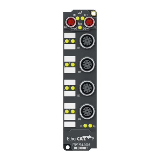
Product overview Introduction EPP3204-0002 | 4-channel analog input Pt100 (RTD) The EPP3204 EtherCAT P Box with analog inputs allows resistance sensors to be connected directly. The module’s circuitry can operate the sensors using 2-, 3- or 4-wire connection techniques. Linearisation over the full temperature range is realised with the aid of a microprocessor. -
Page 10: Technical Data
Resistance measurement: Measuring range 1023 Ω: 1/64 Ω Measuring range 4095 Ω: 1/16 Ω Filter Digital filter. Cut-off frequency parameterizable: 5 Hz … 30 kHz.. Conversion time 2…800 ms, depending on the parameterization Default: approx. 85 ms Diagnostics • Open-circuit recognition • Limit value monitoring Version: 1.4 EPP3204-0002... -
Page 11: Scope Of Supply
35 g, 11 ms Scope of supply Make sure that the following components are included in the scope of delivery: • 1x EPP3204-0002 • 2x protective cap for EtherCAT P socket, M8, red (pre-assembled) • 10x labels, blank (1 strip of 10) Pre-assembled protective caps do not ensure IP67 protection Protective caps are pre-assembled at the factory to protect connectors during transport. -
Page 12: Process Image
Product overview Process image 3.4.1 Assignment of connectors to the process data objects Process image in TwinCAT Connector Process data object RTD RTDInputs Channel 1 RTD RTDInputs Channel 2 RTD RTDInputs Channel 3 RTD RTDInputs Channel 4 Version: 1.4 EPP3204-0002... - Page 13 TRUE if an internal error occurs. TxPDO State This bit is inverted on each update of the measured value. TxPDO Toggle You can determine the present conversion time from the time between two edges of this bit. Value The measured value. EPP3204-0002 Version: 1.4...
-
Page 14: Mounting And Connection
Metal parts brass, nickel-plated Contacts CuZn, gold-plated Installation position variable Protection class IP65, IP66, IP67 (conforms to EN 60529) when screwed together Dimensions (H x W x D) approx. 126 x 30 x 26.5 mm (without connectors) Version: 1.4 EPP3204-0002... -
Page 15: Fixing
Make sure that the box is grounded to low impedance via the functional earth (FE) connection. You can achieve this, for example, by mounting the box on a grounded machine bed. Fig. 1: Connection for functional earth (FE) EPP3204-0002 Version: 1.4... -
Page 16: Ethercat P
EtherCAT P Box to the next EtherCAT P Box in a simple manner. NOTE Note the maximum current. Ensure that the maximum permitted current of 3 A for the M8 connectors is not exceeded when redirecting EtherCAT P. Version: 1.4 EPP3204-0002... -
Page 17: Connectors
Core color Tx + yellow Rx + white Rx - : peripheral voltage, +24 V blue Tx - : control voltage, +24 V orange Housing Shield Shield Shield The core colors apply to EtherCAT P cables and ECP cables from Beckhoff. EPP3204-0002 Version: 1.4... -
Page 18: Status Leds
Each EtherCAT slave has a green LED labelled "Run". The LED signals the status of the slave in the EtherCAT network: Meaning Slave is in "Init" state flashes uniformly Slave is in "Pre-Operational“ state flashes sporadically Slave is in "Safe-Operational" state Slave is in "Operational" state Description of the EtherCAT slave states Version: 1.4 EPP3204-0002... -
Page 19: Conductor Losses
Further information can be found in the quick start guide IO configuration in TwinCAT in chapter "Configuration of EtherCAT P via TwinCAT". Voltage drop on the supply line I = 3 A 0.14 mm² 0.22 mm² Vert. Faktor: 0,22 cm / V 0.34 mm² Cable length (m) EPP3204-0002 Version: 1.4... -
Page 20: Rtd Inputs
- Shield Shield Shield The core colors apply to shielded M12 sensor cables from Beckhoff: ZK2000-7xxx Fig. 5: Connection technology 4.5.2 Cabling • Connect each sensor with a shielded, sheathed cable in which the cable shield is connected to contact 5 of the M12 plug. -
Page 21: Status Leds
M12 socket no. 1-4 R No data transfer to the A/D converter left green Data transfer to A/D converter Function OK right Error: • Broken wire or • measured value outside measuring range or • temperature compensation outside the valid range EPP3204-0002 Version: 1.4... -
Page 22: Ul Requirements
To meet the UL requirements, EtherCAT Box Modules has to be operated only at an ambient temperature range of -25 °C to +55 °C! Marking for UL All EtherCAT Box Modules certified by UL (Underwriters Laboratories) are marked with the following label. Fig. 7: UL label Version: 1.4 EPP3204-0002... -
Page 23: Disposal
Products marked with a crossed-out wheeled bin shall not be discarded with the normal waste stream. The device is considered as waste electrical and electronic equipment. The national regulations for the disposal of waste electrical and electronic equipment must be observed. EPP3204-0002 Version: 1.4... -
Page 24: Commissioning/Configuration
Integrating into a TwinCAT project The procedure for integration in a TwinCAT project is described in these Quick start guide. Measured value processing ADC raw values Filter Vendor Calibration User Calibration Wire Calibration (Two-wire connection) Linearization Scaling Limit monitoring Process data Version: 1.4 EPP3204-0002... -
Page 25: Vendor Calibration
R+ and R- is used to measure the resistance. ◦ The conducting wire is thus not part of the measuring circuit and is not incorporated into the measurement as a source of error. Fig. 8: Resistance measurement with a 4-wire, 3-wire and 2-wire connection technique EPP3204-0002 Version: 1.4... - Page 26 Gv: Vendor Gain 0x80nF:04 0x80nF:06 0x80nF:0A 0x80nF:0C Ov: Vendor Offset 0x80nF:03 0x80nF:05 0x80nF:09 0x80nF:0B : Output value in 1/256 Ω 0x80nE:02 Overflow Y after 16 bits This value is only for fault finding. The register overflows after 16 bits, i.e. at 65536. Version: 1.4 EPP3204-0002...
- Page 27 By knowing the line resistance the resulting measuring error can be compensated. ◦ The cores of the sensor cable must have the same resistance in order for the method to work. Fig. 10: Resistance measurement with a 4-wire, 3-wire and 2-wire connection technique EPP3204-0002 Version: 1.4...
- Page 28 : Output value in 1/256 Ω 0x80nE:02 : Output value in 1/256 Ω 0x80nE:04 : Output value in 1/256 Ω Overflow Y and Y after 16 bits These values are only for fault finding. The registers overflow after 16 bits, i.e. at 65536. Version: 1.4 EPP3204-0002...
-
Page 29: User Calibration And Linearization
Index in the CoE directory with n: channel number with 0 ≤ n ≤ 3 (channel 1 - 4) : Output value of the vendor calibration : User Gain 0x80n0:18 : User Offset 0x80n0:17 : Output value in 1/256 Ω prior to the linearization EPP3204-0002 Version: 1.4... -
Page 30: Scaling, Limits And Formatting
With the values: Index in the CoE directory with n: channel number with 0 ≤ n ≤ 3 (channel 1 - 4) : Output value in 1/100 °C : User Scale Gain 0x80n0:12 : User Scale Offset 0x80n0:11 Y: Output value PDO Version: 1.4 EPP3204-0002... - Page 31 : Output value in 1/256 Ω 0x80nE:02 : Output value in 1/256 Ω 0x80nE:04 Y: Output value PDO Overflow Y and Y after 16 bits These values are only for fault finding. The registers overflow after 16 bits, i.e. at 65536. EPP3204-0002 Version: 1.4...
-
Page 32: Two-Point User Calibration
Reference value in 1/256 Ω Output value in 1/256 Ω prior to the linearization NOTE : Use of the raw value Since the resistance value in index 0x8xxE:02 overflows, the raw value in index 0x8xxE:01 is used for Y Version: 1.4 EPP3204-0002... -
Page 33: Example
The indices accept only integer values. The following entries are to be made in the CoE: Index 0x8000:17 = -12 Index 0x8000:18 = 9960 Subsequently the vendor calibration is to be deactivated (0x8000:0B) and the user calibration activated (0x8000:0A). EPP3204-0002 Version: 1.4... -
Page 34: Limit Value Monitoring
Evaluate the input variables "Limit 1" and "Limit 2" in the process data: Value Meaning Monitoring is not activated for this limit value. The measured value is smaller than the limit value. The measured value is greater than the limit value. Version: 1.4 EPP3204-0002... -
Page 35: Coe Objects
EtherCAT XML Device Description The display matches that of the CoE objects from the EtherCAT XML Device Description. We rec- ommend downloading the latest XML file from the download area of the Beckhoff website and in- stalling it according to installation instructions. - Page 36 6010:02 Overrange 0x00 (0 6010:03 Limit 1 0x00 (0 6010:05 Limit 2 0x00 (0 6010:07 Error 0x00 (0 6010:0E Sync error 0x00 (0 6010:0F TxPDO State 0x00 (0 6010:10 TxPDO Toggle 0x00 (0 6010:11 Value 0x0000 (0 Version: 1.4 EPP3204-0002...
- Page 37 0x0000 (0 800F:02 Calibration gain 3-wire 0x4000 (16384 800F:03 Calibration offset 2-wire 0x0000 (0 800F:04 Calibration gain 2-wire 0x4000 (16384 800F:05 Calibration offset 4-wire 0x0000 (0 800F:06 Calibration gain 4-wire 0x4000 (16384 800F:07 PGA Gain Correction 0x0000 (0 EPP3204-0002 Version: 1.4...
- Page 38 Filter settings 0x0000 (0 8020:16 Calibration intervall 0x0000 (0 8020:17 User calibration offset 0x0000 (0 8020:18 User calibration gain 0x4000 (16384 8020:19 RTD Element 0x0000 (0 8020:1A Connection technology 0x0000 (0 8020:1B Wire calibration 1/32 Ohm 0x0000 (0 Version: 1.4 EPP3204-0002...
- Page 39 Maximum number of modules 0x0004 (4 Code word 0x00000000 (0 F008 [} 54] Subindex Module list 0x04 (4 F010:0 [} 54] F010:01 SubIndex 001 0x00000140 (320 F010:02 SubIndex 002 0x00000140 (320 F010:03 SubIndex 003 0x00000140 (320 F010:04 SubIndex 004 0x00000140 (320 EPP3204-0002 Version: 1.4...
- Page 40 0xFF (255 F080:02 SubIndex 002 0xFF (255 F080:03 SubIndex 003 0xFF (255 F080:04 SubIndex 004 0xFF (255 Flags: RO (Read Only): this object can be read only RW (Read/Write): this object can be read and written to Version: 1.4 EPP3204-0002...
-
Page 41: Object Description And Parameterization
EtherCAT XML Device Description The display matches that of the CoE objects from the EtherCAT XML Device Description. We rec- ommend downloading the latest XML file from the download area of the Beckhoff website and in- stalling it according to installation instructions. - Page 42 User calibration gain Gain of the user calibration UINT16 0x4000 (16384 8000:19 RTD element Sensor type UINT16 0x0000 (0 Pt100 Ni100 Pt1000 Pt500 Pt200 Ni1000 Ni1000 (Siemens) Ni120 Resistance measurement with 1/16 ohm resolution Resistance measurement with 1/64 ohm resolution Version: 1.4 EPP3204-0002...
- Page 43 15 kHz 30 kHz 5 Hz 10 Hz 8010:16 Calibration interval reserved UINT16 0x0000 (0 8010:17 User calibration offset User calibration offset INT16 0x0000 (0 8010:18 User calibration gain Gain of the user calibration UINT16 0x4000 (16384 EPP3204-0002 Version: 1.4...
- Page 44 User scaling offset INT16 0x0000 (0 8020:12 User scale gain Gain of the user scaling INT32 0x00010000 (65536 8020:13 Limit 1 Value for limit 1 INT16 0x0000 (0 8020:14 Limit 2 Value for limit 2 INT16 0x0000 (0 Version: 1.4 EPP3204-0002...
- Page 45 Enable filter, which makes PLC-cycle-synchronous data BOOLEAN 0x00 (0 exchange unnecessary 8030:07 Enable limit 1 Activates limit check for limit 1 BOOLEAN 0x00 (0 8030:08 Enable limit 2 Activates limit check for limit 2 BOOLEAN 0x00 (0 EPP3204-0002 Version: 1.4...
- Page 46 8030:1B Wire calibration 1/32 Only for 2-wire measurements: INT16 0x0000 (0 contains the resistance of the supply line for the tempera- ture sensor (in 1/32 ohm). 5.5.2.2 Objects for regular operation EPP3204 has no such objects. Version: 1.4 EPP3204-0002...
- Page 47 Index (hex) Name Meaning Data type Flags Default 10F0:0 Backup parameter Information for standardized loading and saving of UINT8 0x01 (1 handling backup entries 10F0:01 Checksum Checksum across all backup entries of the EtherCAT UINT32 0x00000000 slave EPP3204-0002 Version: 1.4...
- Page 48 6. PDO Mapping entry (7 bits align) UINT32 0x0000:00, 7 1A03:07 SubIndex 007 7. PDO Mapping entry UINT32 0x6030:0F, 1 1A03:08 SubIndex 008 8. PDO Mapping entry UINT32 0x6030:10, 1 1A03:09 SubIndex 009 9. PDO Mapping entry UINT32 0x6030:11, 16 Version: 1.4 EPP3204-0002...
- Page 49 0x0000 (0 1C33:09 Maximum Delay time UINT32 0x00000000 1C33:0B SM event missed UINT16 0x0000 (0 counter 1C33:0C Cycle exceeded UINT16 0x0000 (0 counter 1C33:0D Shift too short counter UINT16 0x0000 (0 1C33:20 Sync error BOOLEAN 0x00 (0 EPP3204-0002 Version: 1.4...
- Page 50 Validity of the data of the associated TxPDO BOOLEAN 0x00 (0 valid invalid 6010:10 TxPDO Toggle TxPDO toggle is toggled by the slave when the data of BOOLEAN 0x00 (0 the associated TxPDO is updated. 6010:11 Value Analog input date INT16 0x0000 (0 Version: 1.4 EPP3204-0002...
- Page 51 Validity of the data of the associated TxPDO BOOLEAN 0x00 (0 valid invalid 6030:10 TxPDO Toggle TxPDO toggle is toggled by the slave when the data of BOOLEAN 0x00 (0 the associated TxPDO is updated. 6030:11 Value Analog input date INT16 0x0000 (0 EPP3204-0002 Version: 1.4...
- Page 52 Calibration offset 4- Calibration for 4-wire measurement: Offset INT16 0x0000 (0 wire 801F:06 Calibration gain 4- Calibration for 4-wire measurement: Gain UINT16 0x4000 wire (16384 801F:07 PGA Gain Correction Gain correction for Pt1000 measurement INT16 0x0000 (0 Version: 1.4 EPP3204-0002...
- Page 53 Calibration offset 4- Calibration for 4-wire measurement: Offset INT16 0x0000 (0 wire 803F:06 Calibration gain 4- Calibration for 4-wire measurement: Gain UINT16 0x4000 wire (16384 803F:07 PGA Gain Correction Gain correction for Pt1000 measurement INT16 0x0000 (0 EPP3204-0002 Version: 1.4...
- Page 54 BOOLEAN 0x01 (1 LED R for these channels Channel 2 enabled goes out) F080:03 SubIndex 003 Channel 3 disabled BOOLEAN 0x01 (1 Channel 3 enabled F080:04 SubIndex 004 Channel 4 disabled BOOLEAN 0x01 (1 Channel 5 enabled Version: 1.4 EPP3204-0002...
-
Page 55: Restoring The Delivery State
Fig. 15: Entering a restore value in the Set Value dialog Alternative restore value In some older terminals / boxes the backup objects can be switched with an alternative restore value: Decimal value: 1819238756 Hexadecimal value: 0x6C6F6164 An incorrect entry for the restore value has no effect. EPP3204-0002 Version: 1.4... -
Page 56: Decommissioning
Commissioning/Configuration Decommissioning WARNING Risk of electric shock! Bring the bus system into a safe, de-energized state before starting disassembly of the devices! Version: 1.4 EPP3204-0002... -
Page 57: Appendix
(ph-Value > 12) > 40°C: not resistant Acetic acid not resistant Argon (technical clean) resistant • resistant: Lifetime several months • non inherently resistant: Lifetime several weeks • not resistant: Lifetime several hours resp. early decomposition EPP3204-0002 Version: 1.4... -
Page 58: Accessories
Torque cable key for M12 / wrench size 13 for ZB8801-0000 ZB8801-0003 Torque cable key for M12 field assembly / wrench size 18 for ZB8801-0000 Further accessories Further accessories can be found in the price list for fieldbus components from Beckhoff and online at https://www.beckhoff.com. Version: 1.4 EPP3204-0002... -
Page 59: Version Identification Of Ethercat Devices
Associated and synonymous with each revision there is usually a description (ESI, EtherCAT Slave Information) in the form of an XML file, which is available for download from the Beckhoff web site. From 2014/01 the revision is shown on the outside of the IP20 terminals, see Fig. “EL5021 EL terminal, standard IP20 IO device with batch number and revision ID (since 2014/01)”. -
Page 60: Version Identification Of Ep/Epi/Epp/Er/Eri Boxes
Version identification of EP/EPI/EPP/ER/ERI boxes The serial number/ data code for Beckhoff IO devices is usually the 8-digit number printed on the device or on a sticker. The serial number indicates the configuration in delivery state and therefore refers to a whole production batch, without distinguishing the individual modules of a batch. -
Page 61: Beckhoff Identification Code (Bic)
6.3.3 Beckhoff Identification Code (BIC) The Beckhoff Identification Code (BIC) is increasingly being applied to Beckhoff products to uniquely identify the product. The BIC is represented as a Data Matrix Code (DMC, code scheme ECC200), the content is based on the ANSI standard MH10.8.2-2016. - Page 62 Fig. 18: Example DMC 1P072222SBTNk4p562d71KEL1809 Q1 51S678294 An important component of the BIC is the Beckhoff Traceability Number (BTN, position 2). The BTN is a unique serial number consisting of eight characters that will replace all other serial number systems at Beckhoff in the long term (e.g.
-
Page 63: Electronic Access To The Bic (Ebic)
Electronic access to the BIC (eBIC) Electronic BIC (eBIC) The Beckhoff Identification Code (BIC) is applied to the outside of Beckhoff products in a visible place. If possible, it should also be electronically readable. Decisive for the electronic readout is the interface via which the product can be electronically addressed. - Page 64 EtherCAT, the eBIC of the top-level device is located in the CoE object directory 0x10E2:01 and the eBICs of the sub-devices follow in 0x10E2:nn. Profibus/Profinet/DeviceNet… Devices Currently, no electronic storage and readout is planned for these devices. Version: 1.4 EPP3204-0002...
-
Page 65: Support And Service
Please contact your Beckhoff branch office or representative for local support and service on Beckhoff products! The addresses of Beckhoff's branch offices and representatives round the world can be found on her internet pages: https://www.beckhoff.com You will also find further documentation for Beckhoff components there. - Page 67 More Information: www.beckhoff.com/epp3204-0002/ Beckhoff Automation GmbH & Co. KG Hülshorstweg 20 33415 Verl Germany Phone: +49 5246 9630 info@beckhoff.com www.beckhoff.com...
Need help?
Do you have a question about the EPP3204-0002 and is the answer not in the manual?
Questions and answers