Sign In
Upload
Download
Table of Contents
Contents
Add to my manuals
Delete from my manuals
Share
URL of this page:
HTML Link:
Bookmark this page
Add
Manual will be automatically added to "My Manuals"
Print this page
×
Bookmark added
×
Added to my manuals
Manuals
Brands
Beckhoff Manuals
I/O Systems
EK1101
Documentation
Beckhoff EK1101 Documentation
Ethercat bus coupler
Hide thumbs
1
2
3
4
5
6
7
8
9
10
11
12
13
14
15
16
17
18
19
20
21
22
23
24
25
26
27
28
29
30
31
32
33
34
35
36
37
38
39
40
41
42
43
44
45
46
47
48
49
50
51
52
53
54
55
56
57
58
59
60
61
62
63
64
65
66
67
68
69
70
71
72
73
74
75
76
77
78
79
80
81
82
83
84
85
page
of
85
Go
/
85
Contents
Table of Contents
Bookmarks
Table of Contents
Table of Contents
1 Foreword
Overview Ethercat Coupler
Notes on the Documentation
Safety Instructions
Documentation Issue Status
Version Identification of Ethercat Devices
Fig. 1 EL5021 el Terminal, Standard IP20 IO Device with Batch Number and Revision ID (Since 2014/01)
Fig. 2 EK1100 Ethercat Coupler, Standard IP20 IO Device with Batch Number
Fig. 3 CU2016 Switch with Batch Number
Fig. 4 EL3202-0020 with Batch Numbers 26131006 and Unique ID-Number 204418
Fig. 5 EP1258-00001 IP67 Ethercat Box with Batch Number 22090101 and Unique Serial Number 158102
Fig. 6 EP1908-0002 IP67 Ethercat Safety Box with Batch Number 071201FF and Unique Serial Number 00346070
Fig. 7 EL2904 IP20 Safety Terminal with Batch Number/Date Code 50110302 and Unique Serial Num- Ber 00331701
Fig. 8 ELM3604-0002 Terminal with ID Number (QR Code) 100001051 and Unique Serial Number 44160201
2 Product Overview
Overview of Ethercat Couplers
Fig. 9 Ethercat Coupler Communication Diagram
Coupler with RJ45 Connection
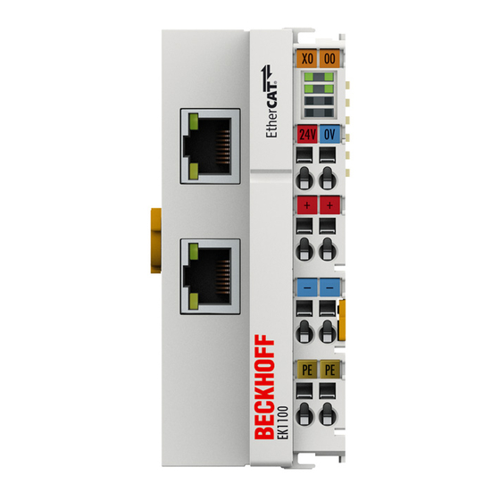
Ek1100
EK1101, EK1101-XXXX
Fig. 10 Identification of FHC Port at EK1122-0080 and EK1101-0080
Fig. 11 Recommended Combination of Ethernet Ports
Fig. 12 Configuration of a Fast Hot Connect Group
Fig. 13 Marking in the Twincat System Manager
Coupler with M8 Connection
Ek1100-0008
Fig. 14 DC Master Setting
Coupler with Optical Fiber Connection
Ek1501
Ek1501-0010
Coupler with POF Connection
Ek1541
3 Basics
Ethercat Basics
Ethercat Coupler Port Allocation
Fig. 15 Example: EK1100 / EK1100-0008 Ethercat Coupler with 3 Ports
Fig. 16 Internal and External Port Assignment for Bus Coupler EK1100 and EK1100-0008
Ethercat State Machine
Fig. 17 States of the Ethercat State Machine
Coe - Interface: Notes
Ekxxxx - Optional Distributed Clocks Support
Fig. 18 DC Tab for Indicating the Distributed Clocks Function
Fig. 19 Advanced Distributed Clocks Settings in the Ethercat Master
Fig. 20 Twincat Setting for Using this Component as Reference Clock
4 Mounting and Wiring
Instructions for ESD Protection
Installation on Mounting Rails
Fig. 21 Spring Contacts of the Beckhoff I/O Components
Fig. 22 Attaching on Mounting Rail
Fig. 23 Disassembling of Terminal
Installation Instructions for Enhanced Mechanical Load Capacity
Fig. 24 Power Contact on Left Side
Installation Positions
Fig. 25 Recommended Distances for Standard Installation Position
Connection System
Fig. 26 Other Installation Positions
Fig. 27 Standard Wiring
Fig. 28 Pluggable Wiring
Fig. 29 High Density Terminals
Wiring
Fig. 30 Connecting a Cable on a Terminal Point
Ethercat Cabling - Wire-Bound
M8 Connector Cabling
Fig. 31 System Manager Current Calculation
Fig. 32 ZK1090-3131-0Xxx
Nut Torque for Connectors
Fig. 33 X1 and X2 of EK1100-0008
Fig. 34 Ethercat Box with M8 Connectors
Power Supply, Potential Groups
Fig. 35 Potential Diagram Ekxxxx
Fig. 36 GND Concept Ekxxxx
Mounting of Passive Terminals
UL Notice
Fig. 37 Correct Configuration
Fig. 38 Incorrect Configuration
ATEX - Special Conditions (Extended Temperature Range)
ATEX Documentation
5 Commissioning/Application Notes
Configuration Overview
Application Notes
Optical Fiber Application Notes
Fig. 39 EK1501
POF Application Notes
Fig. 40 EK1541
Fig. 41 Latching Lug with Release Catch on the POF Duplex Plug
Notes Regarding Assembly of POF Cables with the Connector Set ZS1090-0008
6 Error Handling and Diagnostics
Diagnostic Leds
7 Appendix
Safety Instructions and Behavioral Rules for Class 1 Laser
Ethercat al Status Codes
Firmware Compatibility
Firmware Update El/Es/Em/Epxxxx
Device Description ESI File/Xml
Firmware Explanation
Updating Controller Firmware *.Efw
FPGA Firmware *.Rbf
Simultaneous Updating of Several Ethercat Devices
Support and Service
List of Illustrations
Advertisement
Quick Links
1
Overview Ethercat Coupler
2
Fig. 2 Ek1100 Ethercat Coupler, Standard Ip20 Io Device with Batch Number
3
Ek1100
Download this manual
Documentation
EK110x, EK15xx
EtherCAT Bus Coupler
Version:
Date:
3.6
2017-10-05
Table of
Contents
Previous
Page
Next
Page
1
2
3
4
5
Advertisement
Chapters
Table of Contents
3
List of Illustrations
84
Table of Contents
Need help?
Do you have a question about the EK1101 and is the answer not in the manual?
Ask a question
Questions and answers
Related Manuals for Beckhoff EK1101
I/O Systems Beckhoff EK1100 Documentation
Ethercat bus coupler (85 pages)
I/O Systems Beckhoff EK1541 Documentation
Ethercat bus coupler (85 pages)
I/O Systems Beckhoff EK1501 Documentation
Ethercat bus coupler (85 pages)
I/O Systems Beckhoff EtherCAT EL600x Series Documentation
Serial interface terminals (204 pages)
I/O Systems Beckhoff EtherCAT EL6022 Documentation
Serial interface terminals (204 pages)
I/O Systems Beckhoff EtherCAT EL6001 Documentation
Serial interface terminals (204 pages)
I/O Systems Beckhoff EtherCAT EL6002 Documentation
Serial interface terminals (204 pages)
I/O Systems Beckhoff EPI3 Series Documentation
Io-link box modules with analog inputs (98 pages)
I/O Systems Beckhoff EP4374 Documentation
Ethercat box with analog inputs and outputs (53 pages)
I/O Systems Beckhoff EP8309-1022 Manual
Multi-functional i/o box (90 pages)
I/O Systems Beckhoff EPI1 Series Documentation
Io-link box modules with digital inputs (83 pages)
I/O Systems Beckhoff EPI2 Series Documentation
Io-link box modules with digital outputs (94 pages)
I/O Systems Beckhoff EPP2 Series Documentation
Ethercat p box modules with digital outputs (153 pages)
I/O Systems Beckhoff EPP4374-0002 Manual
Ethercat p box with analog inputs and outputs (60 pages)
I/O Systems Beckhoff EPP3204-0002 Documentation
4-channel analog input pt100 (rtd) (67 pages)
I/O Systems Beckhoff EP9224-2037 Documentation
Ethercat box, 4-port junction, with power supply, enp, b17 (83 pages)
This manual is also suitable for:
Ek1100
Ek1501-0010
Ek1541
Ek1501
Ek1101-0080
Table of Contents
Save PDF
Print
Rename the bookmark
Delete bookmark?
Delete from my manuals?
Login
Sign In
OR
Sign in with Facebook
Sign in with Google
Upload manual
Upload from disk
Upload from URL


Need help?
Do you have a question about the EK1101 and is the answer not in the manual?
Questions and answers