
Related Manuals for Beckhoff EPP4374-0002


Summary of Contents for Beckhoff EPP4374-0002
- Page 1 Documentation | EN EPP4374-0002 EtherCAT P Box with analog inputs and outputs 2023-02-01 | Version: 1.3...
-
Page 3: Table Of Contents
Version identification of EtherCAT devices .................. 52 6.3.1 General notes on marking.................... 52 6.3.2 Version identification of EP/EPI/EPP/ER/ERI boxes............ 53 6.3.3 Beckhoff Identification Code (BIC) ................... 54 6.3.4 Electronic access to the BIC (eBIC)................. 56 Support and Service........................ 58 EPP4374-0002 Version: 1.3... - Page 4 Table of contents Version: 1.3 EPP4374-0002...
-
Page 5: Foreword
All the components are supplied in particular hardware and software configurations appropriate for the application. Modifications to hardware or software configurations other than those described in the documentation are not permitted, and nullify the liability of Beckhoff Automation GmbH & Co. KG. Personnel qualification This description is only intended for trained specialists in control, automation and drive engineering who are familiar with the applicable national standards. -
Page 6: Notes On The Documentation
, XTS and XPlanar are registered trademarks of and licensed by Beckhoff Automation GmbH. Other designations used in this publication may be trademarks whose use by third parties for their own purposes could violate the rights of the owners. Patent Pending... -
Page 7: Documentation Issue Status
YY - year of production 10 - year of production 2010 FF - firmware version 02 - firmware version 02 HH - hardware version 01 - hardware version 01 Further information on this topic: Version identification of EtherCAT devices [} 52]. EPP4374-0002 Version: 1.3... -
Page 8: Product Group: Ethercat P Box Modules
EtherCAT P Box modules are EtherCAT P slaves with degree of protection IP67. They are designed for operation in wet, dirty or dusty industrial environments. EtherCAT basics A detailed description of the EtherCAT system can be found in the EtherCAT system documentation. Version: 1.3 EPP4374-0002... -
Page 9: Product Overview
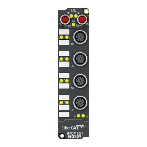
Output - Shield EtherCAT Box with analog inputs and outputs EPP4374-0002 has two analog inputs and two analog outputs. The signal range can be individually parameterized for each analog input and output: • -10 … +10 V • 0 … 10 V •... -
Page 10: Technical Data
Product overview Technical data All values are typical values over the entire temperature range, unless stated otherwise. Technical data EPP4374-0002 Fieldbus Fieldbus EtherCAT Connection EtherCAT P: Combined connection for EtherCAT and supply voltages Input: 1 x M8 socket, 4-pin, P-coded... - Page 11 Product overview Technical data EPP4374-0002 Environmental conditions Ambient temperature during operation -25…+60 °C -25…+55 °C according to cURus [} 26] 0…+55 °C according to ATEX Ambient temperature during storage -40…+85 °C Vibration / shock resistance conforms to EN 60068-2-6 / EN 60068-2-27; see also Additional checks [} 12].
-
Page 12: Scope Of Supply
Scope of supply Make sure that the following components are included in the scope of delivery: • 1x EtherCAT P Box EPP4374-0002 • 2x protective cap for EtherCAT P socket, M8, red (pre-assembled) • 10x labels, blank (1 strip of 10) Pre-assembled protective caps do not ensure IP67 protection Protective caps are pre-assembled at the factory to protect connectors during transport. -
Page 13: Process Image
1: value less than limit 2 (set in object 0x80x0:14 [} 38]) 2: value greater than limit 2 (set in object 0x80x0:14 [} 38]) 3: value equal to limit 2 (set in object 0x80x0:14 [} 38]) • Error: This bit is set if overrange or underrange was detected. EPP4374-0002 Version: 1.3... - Page 14 The data of the second analog channel have the same structure as those of the first channel. AO Outputs Channel 3 The data for the third analog channel can be found under AO Outputs Channel 3. AO Outputs Channel 4 The data of the forth analog channel have the same structure as those of the third channel. Version: 1.3 EPP4374-0002...
-
Page 15: Mounting And Cabling
Metal parts brass, nickel-plated Contacts CuZn, gold-plated Installation position variable Protection class IP65, IP66, IP67 (conforms to EN 60529) when screwed together Dimensions (H x W x D) approx. 126 x 30 x 26.5 mm (without connectors) EPP4374-0002 Version: 1.3... -
Page 16: Fixing
Fig. 1: Connection for functional earth (FE) 4.1.4 Tightening torques for plug connectors Screw connectors tight with a torque wrench. (e.g. ZB8801 from Beckhoff) Connector diameter Tightening torque 0.4 Nm 0.6 Nm... -
Page 17: Cabling
Guidelines Follow these guidelines to ensure IP67 protection: • Mount plugs with the torque values specified below. Use a torque wrench, e.g. Beckhoff ZB8801. • Seal unused connectors with protective caps. • Ensure the correct seating of pre-assembled protective caps. -
Page 18: Ethercat P
EtherCAT P Box to the next EtherCAT P Box in a simple manner. NOTE Note the maximum current. Ensure that the maximum permitted current of 3 A for the M8 connectors is not exceeded when redirecting EtherCAT P. Version: 1.3 EPP4374-0002... - Page 19 Core color Tx + yellow Rx + white Rx - : peripheral voltage, +24 V blue Tx - : control voltage, +24 V orange Housing Shield Shield Shield The core colors apply to EtherCAT P cables and ECP cables from Beckhoff. EPP4374-0002 Version: 1.3...
- Page 20 Each EtherCAT slave has a green LED labelled "Run". The LED signals the status of the slave in the EtherCAT network: Meaning Slave is in "Init" state flashes uniformly Slave is in "Pre-Operational“ state flashes sporadically Slave is in "Safe-Operational" state Slave is in "Operational" state Description of the EtherCAT slave states Version: 1.3 EPP4374-0002...
- Page 21 Further information can be found in the quick start guide IO configuration in TwinCAT in chapter "Configuration of EtherCAT P via TwinCAT". Voltage drop on the supply line I = 3 A 0.14 mm² 0.22 mm² Vert. Faktor: 0,22 cm / V 0.34 mm² Cable length (m) EPP4374-0002 Version: 1.3...
-
Page 22: Analog Interfaces
EMC shield clamp Depending on the application it may be necessary to additionally attach the shield of the sensor ca- bles at the signal inputs of the box with shield clamps ZB8513-0002. See Chapter: “Accessories”, section “Cables” [} 51]. Version: 1.3 EPP4374-0002... - Page 23 Correct function is indicated if the green Run LED is on and the red Error LED is off. Status LEDs at M12 connections 3 and 4 (outputs) Connection Display Meaning M12 socket no. 3 and 4 No data transfer to the D/A converter left green Data transfer to the D/A converter EPP4374-0002 Version: 1.3...
- Page 24 The sensor is connected via In+ and In-. The sensor can optionally be operated/supplied with 24 V Analog outputs The actuator is connected via output +/- and output GND. The actuator can optionally be operated/supplied with 24 V Version: 1.3 EPP4374-0002...
- Page 25 There are sensors that have an analog input in addition to their analog output. If the analog output of the sensor is not potential-free, the following recommendation applies: Connect pin 3 and pin 4 of the analog output of EP4374-0002 with a jumper. Otherwise, measuring errors may occur. EPP4374-0002 Version: 1.3...
-
Page 26: Ul Requirements
To meet the UL requirements, EtherCAT Box Modules has to be operated only at an ambient temperature range of -25 °C to +55 °C! Marking for UL All EtherCAT Box Modules certified by UL (Underwriters Laboratories) are marked with the following label. Fig. 7: UL label Version: 1.3 EPP4374-0002... -
Page 27: Disposal
Products marked with a crossed-out wheeled bin shall not be discarded with the normal waste stream. The device is considered as waste electrical and electronic equipment. The national regulations for the disposal of waste electrical and electronic equipment must be observed. EPP4374-0002 Version: 1.3... -
Page 28: Commissioning And Configuration
Commissioning and configuration Commissioning and configuration Integrating into a TwinCAT project The procedure for integration in a TwinCAT project is described in these Quick start guide. Version: 1.3 EPP4374-0002... -
Page 29: Setting Signal Ranges
F800:04 TwinCAT Proceed as follows to change the signal range of an analog channel in TwinCAT: 1. Double-click the IO module EPP4374-0002 in the IO tree. 2. Click on the "CoE - Online" tab. ð The CoE directory is displayed. -
Page 30: Object Overview
EtherCAT XML Device Description The display matches that of the CoE objects from the EtherCAT XML Device Description. We rec- ommend downloading the latest XML file from the download area of the Beckhoff website and in- stalling it according to installation instructions. - Page 31 0x00001388 (5000 1C32:08 Command 0x0000 (0 1C32:09 Maximum delay time 0x00001388 (5000 1C32:0B SM event missed counter 0x0000 (0 1C32:0C Cycle exceeded counter 0x0000 (0 1C32:0D Shift too short counter 0x0000 (0 1C32:20 Sync error 0x00 (0 EPP4374-0002 Version: 1.3...
- Page 32 6010:02 Overrange 0x00 (0 6010:03 Limit 1 0x00 (0 6010:05 Limit 2 0x00 (0 6010:07 Error 0x00 (0 6010:0E Sync error 0x00 (0 6010:0F TxPDO State 0x00 (0 6010:10 TxPDO Toggle 0x00 (0 6010:11 Value 0x0000 (0 Version: 1.3 EPP4374-0002...
- Page 33 User scale offset 0x0000 (0 8010:12 User scale gain 0x00010000 (65536 8010:13 Limit 1 0x0000 (0 8010:14 Limit 2 0x0000 (0 8010:15 Filter settings 0x0000 (0 8010:17 User calibration offset 0x0000 (0 8010:18 User calibration gain 0x4000 (16384 EPP4374-0002 Version: 1.3...
- Page 34 [} 47] 802F:01 R0 Calibration Offset 0x0000 (0 802F:02 R0 Calibration Gain 0x4000 (16384 802F:03 R1 Calibration Offset 0x0000 (0 802F:04 R1 Calibration Gain 0x4000 (16384 802F:05 R2 Calibration Offset 0x0000 (0 802F:06 R2 Calibration Gain 0x4000 (16384 Version: 1.3 EPP4374-0002...
- Page 35 Input type Ch2 0x0000 (0 F800:03 Output type Ch3 0x0000 (0 F800:04 Output type Ch4 0x0000 (0 Legend Flags: RO (Read Only): this object can be read only RW (Read/Write): this object can be read and written to EPP4374-0002 Version: 1.3...
-
Page 36: Object Description And Parameterization
EtherCAT XML Device Description The display matches that of the CoE objects from the EtherCAT XML Device Description. We rec- ommend downloading the latest XML file from the download area of the Beckhoff website and in- stalling it according to installation instructions. - Page 37 60 Hz FIR IIR 1 IIR 2 IIR 3 IIR 4 IIR 5 IIR 6 IIR 71 IIR 8 8000:17 User calibration offset User calibration: Offset INT16 0x0000 (0 8000:18 User calibration gain User calibration: Gain INT16 0x4000 (16384 EPP4374-0002 Version: 1.3...
- Page 38 60 Hz FIR IIR 1 IIR 2 IIR 3 IIR 4 IIR 5 IIR 6 IIR 71 IIR 8 8010:17 User calibration offset User calibration: Offset INT16 0x0000 (0 8010:18 User calibration gain User calibration: Gain INT16 0x4000 (16384 Version: 1.3 EPP4374-0002...
- Page 39 327 ms (32767/100) for the output value to change from the maximum value (32767) to the default value in the event of a fault. 8020:15 User calibration offset User calibration: Offset INT16 0x0000 (0 8020:16 User calibration gain User calibration: Gain UINT16 0x4000 (16384 EPP4374-0002 Version: 1.3...
- Page 40 Input signal range for channel 2 (values see channel 1) UINT16 0x0000 (0 F800:03 Output type Ch3 Output signal range for channel 3 UINT16 0x0000 (0 -10…+10 V 0...20 mA 4...20 mA 0...10 V F800:04 Output type Ch4 Output signal range for channel 4 (values see channel 3) UINT16 0x0000 (0 Version: 1.3 EPP4374-0002...
-
Page 41: Standard Objects (0X1000-0X1Fff)
Index (hex) Name Meaning Data type Flags Default 1600:0 AO Outputs Ch.3 PDO Mapping RxPDO 1 UINT8 0x01 (1 1600:01 SubIndex 001 1. PDO Mapping entry (object 0x7020 (AO outputs Ch.3), UINT32 0x7020:11, 16 entry 0x11 (Analog output)) EPP4374-0002 Version: 1.3... - Page 42 0x0F (TxPDO State)) 1A00:0A SubIndex 010 10. PDO Mapping entry (object 0x6000 (AI Inputs), entry UINT32 0x6000:10, 1 0x10 (TxPDO Toggle)) 1A00:0B SubIndex 011 11. PDO Mapping entry (object 0x6000 (AI Inputs), entry UINT32 0x6000:11, 16 0x11 (Value)) Version: 1.3 EPP4374-0002...
- Page 43 0x02 (2 1C12:01 Subindex 001 1st allocated RxPDO (contains the index of the associ- UINT16 0x1600 ated RxPDO mapping object) (5632 1C12:02 Subindex 002 2nd allocated RxPDO (contains the index of the associ- UINT16 0x1601 ated RxPDO mapping object) (5633 EPP4374-0002 Version: 1.3...
- Page 44 Shift too short counter Number of occasions that the interval between SYNC0 UINT16 0x0000 (0 and SYNC1 event was too short (DC mode only) 1C32:20 Sync error The synchronization was not correct in the last cycle BOOLEAN 0x00 (0 (outputs were output too late; DC mode only) Version: 1.3 EPP4374-0002...
- Page 45 1C33:0B SM event missed as 0x1C32:11 UINT16 0x0000 (0 counter 1C33:0C Cycle exceeded as 0x1C32:12 UINT16 0x0000 (0 counter 1C33:0D Shift too short counter as 0x1C32:13 UINT16 0x0000 (0 1C33:20 Sync error as 0x1C32:32 BOOLEAN 0x00 (0 EPP4374-0002 Version: 1.3...
-
Page 46: Profile-Specific Objects (0X6000-0Xffff)
Analog output Analog output data INT16 0x0000 (0 Index 800E AI Internal data Ch.1 Index (hex) Name Meaning Data type Flags Default 800E:0 AI Internal data Ch.1 UINT8 0x01 (1 800E:01 ADC raw value INT16 0x0000 (0 Version: 1.3 EPP4374-0002... - Page 47 0x4000 (16384 Index 803E AO Internal data Ch.4 Index (hex) Name Meaning Data type Flags Default 803E:0 AO Internal data Ch.4 UINT8 0x01 (1 803E:01 DAC raw value This is the raw DAC value. UINT16 0x0000 (0 EPP4374-0002 Version: 1.3...
- Page 48 Index (hex) Name Meaning Data type Flags Default F010:0 Module list UINT8 0x04 (4 F010:01 SubIndex 001 UINT32 0x0000012C (300 F010:02 SubIndex 002 UINT32 0x0000012C (300 F010:03 SubIndex 003 UINT32 0x00000190 (400 F010:04 SubIndex 004 UINT32 0x00000190 (400 Version: 1.3 EPP4374-0002...
-
Page 49: Restoring The Delivery State
Fig. 9: Entering a restore value in the Set Value dialog Alternative restore value In some older terminals / boxes the backup objects can be switched with an alternative restore value: Decimal value: 1819238756 Hexadecimal value: 0x6C6F6164 An incorrect entry for the restore value has no effect. EPP4374-0002 Version: 1.3... -
Page 50: Appendix
(ph-Value > 12) > 40°C: not resistant Acetic acid not resistant Argon (technical clean) resistant • resistant: Lifetime several months • non inherently resistant: Lifetime several weeks • not resistant: Lifetime several hours resp. early decomposition Version: 1.3 EPP4374-0002... -
Page 51: Accessories
Torque cable key for M12 / wrench size 13 for ZB8801-0000 ZB8801-0003 Torque cable key for M12 field assembly / wrench size 18 for ZB8801-0000 Further accessories Further accessories can be found in the price list for fieldbus components from Beckhoff and online at https://www.beckhoff.com. EPP4374-0002 Version: 1.3... -
Page 52: Version Identification Of Ethercat Devices
Associated and synonymous with each revision there is usually a description (ESI, EtherCAT Slave Information) in the form of an XML file, which is available for download from the Beckhoff web site. From 2014/01 the revision is shown on the outside of the IP20 terminals, see Fig. “EL5021 EL terminal, standard IP20 IO device with batch number and revision ID (since 2014/01)”. -
Page 53: Version Identification Of Ep/Epi/Epp/Er/Eri Boxes
Version identification of EP/EPI/EPP/ER/ERI boxes The serial number/ data code for Beckhoff IO devices is usually the 8-digit number printed on the device or on a sticker. The serial number indicates the configuration in delivery state and therefore refers to a whole production batch, without distinguishing the individual modules of a batch. -
Page 54: Beckhoff Identification Code (Bic)
6.3.3 Beckhoff Identification Code (BIC) The Beckhoff Identification Code (BIC) is increasingly being applied to Beckhoff products to uniquely identify the product. The BIC is represented as a Data Matrix Code (DMC, code scheme ECC200), the content is based on the ANSI standard MH10.8.2-2016. - Page 55 Fig. 12: Example DMC 1P072222SBTNk4p562d71KEL1809 Q1 51S678294 An important component of the BIC is the Beckhoff Traceability Number (BTN, position 2). The BTN is a unique serial number consisting of eight characters that will replace all other serial number systems at Beckhoff in the long term (e.g.
-
Page 56: Electronic Access To The Bic (Ebic)
Electronic access to the BIC (eBIC) Electronic BIC (eBIC) The Beckhoff Identification Code (BIC) is applied to the outside of Beckhoff products in a visible place. If possible, it should also be electronically readable. Decisive for the electronic readout is the interface via which the product can be electronically addressed. - Page 57 EtherCAT, the eBIC of the top-level device is located in the CoE object directory 0x10E2:01 and the eBICs of the sub-devices follow in 0x10E2:nn. Profibus/Profinet/DeviceNet… Devices Currently, no electronic storage and readout is planned for these devices. EPP4374-0002 Version: 1.3...
-
Page 58: Support And Service
Please contact your Beckhoff branch office or representative for local support and service on Beckhoff products! The addresses of Beckhoff's branch offices and representatives round the world can be found on her internet pages: https://www.beckhoff.com You will also find further documentation for Beckhoff components there. - Page 60 More Information: www.beckhoff.com/epp4374-0002 Beckhoff Automation GmbH & Co. KG Hülshorstweg 20 33415 Verl Germany Phone: +49 5246 9630 info@beckhoff.com www.beckhoff.com...
Need help?
Do you have a question about the EPP4374-0002 and is the answer not in the manual?
Questions and answers