
Related Manuals for Beckhoff EP4174-0002


Summary of Contents for Beckhoff EP4174-0002
- Page 1 Documentation | EN EP4174-0002 4-channel analog output, ±10 V, 0/4…20 mA, 16 bit, differential 2024-10-10 | Version: 1.6...
-
Page 3: Table Of Contents
Objects to be parameterized during commissioning ............ 32 5.3.2 Objects for regular operation.................... 37 5.3.3 Standard objects (0x1000-0x1FFF) ................. 37 5.3.4 Profile-specific objects (0x6000-0xFFFF) ................ 40 Restore the delivery state ....................... 43 6 Appendix .............................. 44 General operating conditions ...................... 44 Accessories ............................. 45 EP4174-0002 Version: 1.6... - Page 4 Version identification of EtherCAT devices .................. 47 6.4.1 General notes on marking.................... 47 6.4.2 Version identification of IP67 modules ................ 48 6.4.3 Beckhoff Identification Code (BIC) ................... 49 6.4.4 Electronic access to the BIC (eBIC)................. 51 Support and Service........................ 53 Version: 1.6 EP4174-0002...
-
Page 5: Foreword
, XTS and XPlanar are registered trademarks of and licensed by Beckhoff Automation GmbH. Other designations used in this publication may be trademarks whose use by third parties for their own purposes could violate the rights of the owners. Patent Pending... -
Page 6: Safety Instructions
All the components are supplied in particular hardware and software configurations appropriate for the application. Modifications to hardware or software configurations other than those described in the documentation are not permitted, and nullify the liability of Beckhoff Automation GmbH & Co. KG. Personnel qualification This description is only intended for trained specialists in control, automation and drive engineering who are familiar with the applicable national standards. -
Page 7: Documentation Issue Status
YY - year of production 10 - year of production 2010 FF - firmware version 02 - firmware version 02 HH - hardware version 01 - hardware version 01 Further information on this topic: Version identification of EtherCAT devices [} 47]. EP4174-0002 Version: 1.6... -
Page 8: Ethercat Box - Introduction
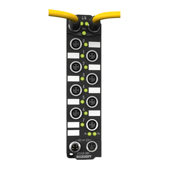
• digital outputs with 0.5 or 2 A output current • analog inputs and outputs with 16 bit resolution • Thermocouple and RTD inputs • Stepper motor modules XFC (eXtreme Fast Control Technology) modules, including inputs with time stamp, are also available. Version: 1.6 EP4174-0002... - Page 9 Fig. 3: EtherCAT Box with M12 connections for sensors/actuators Basic EtherCAT documentation You will find a detailed description of the EtherCAT system in the Basic System Documentation for EtherCAT, which is available for download from our website (www.beckhoff.com) under Downloads. EP4174-0002 Version: 1.6...
-
Page 10: Product Overview
The analog actuators are supplied from the load voltage (freely selectable up to 30 V ). The applied load voltage is available for actuator supply of further EtherCAT Box modules. Quick links Technical data [} 11] Process image [} 14] Dimensions [} 15] Signal interface [} 22] Version: 1.6 EP4174-0002... -
Page 11: Technical Data
Auxiliary voltage output From the supply voltage U , can be selected as desired up to 30 V Housing data Dimensions W x H x D 30 mm x 126 mm x 26.5 mm (without connectors) Weight approx. 165 g Installation position variable Material PA6 (polyamide) EP4174-0002 Version: 1.6... -
Page 12: Scope Of Supply
Scope of supply Make sure that the following components are included in the scope of delivery: • 1x EtherCAT Box EP4174-0002 • 2x protective cap for EtherCAT socket, M8, green (pre-assembled) • 1x protective cap for supply voltage input, M8, transparent (pre-assembled) •... -
Page 13: Status Leds
Power supply Display Meaning the power supply voltage, Us, is not present green illuminated the power supply voltage, Us, is present the power supply voltage, Up, is not present green illuminated The power supply voltage, Up, is present EP4174-0002 Version: 1.6... -
Page 14: Process Image
The data for the first analog channel can be found under AO Outputs Channel 1. AO Outputs Channel 2 to 4 The data of analog channels 2 to 4 have the same structure as those of the first channel. Version: 1.6 EP4174-0002... -
Page 15: Mounting And Connection
CuZn, gold-plated Power feed through max. 4 A Installation position variable Protection class IP65, IP66, IP67 (conforms to EN 60529) when screwed together Dimensions (H x W x D) approx. 126 x 30 x 26.5 mm (without connectors) EP4174-0002 Version: 1.6... -
Page 16: Fixing
Mount the module with two M3 screws on the mounting holes in the corners of the module. The mounting holes have no thread. 4.1.3 Tightening torques for plug connectors Screw connectors tight with a torque wrench. (e.g. ZB8801 from Beckhoff) Connector diameter Tightening torque 0.4 Nm 0.6 Nm... -
Page 17: Ethercat
For standardization, the core colors of the ZB9030, ZB9032 and ZK1090-3xxx-xxxx cables have been changed to the EN61918 core colors: yellow, orange, white, blue. So there are different color codes in circulation. The electrical properties of the cables have been retained when the core colors were changed. EP4174-0002 Version: 1.6... -
Page 18: Status Leds
(CAT5) according to EN 50173 or ISO/IEC 11801 should be used. EtherCAT uses four wires for signal transmission. Thanks to automatic line detection ("Auto MDI-X"), both symmetrical (1:1) or cross-over cables can be used between Beckhoff EtherCAT. Detailed recommendations for the cabling of EtherCAT devices Version: 1.6... -
Page 19: Supply Voltages
In some types of EtherCAT Box modules the ground potentials GND and GND are connected. • If several EtherCAT Box modules are supplied with the same electrically isolated voltages, check whether there is an EtherCAT Box among them in which the ground potentials are connected. EP4174-0002 Version: 1.6... -
Page 20: Connectors
Control voltage Brown Peripheral voltage White GND to U Blue GND to U Black The core colors apply to cables of the type: Beckhoff ZK2020-3xxx-xxxx 4.3.2 Status LEDs Display Meaning (control voltage) The supply voltage U is not available. green illuminated The supply voltage U is available. -
Page 21: Conductor Losses
Vert. Faktor: 0,45 cm / V Vert. Faktor: 0,4 0.34 mm² Vert. Faktor: 0,45 cm / V Vert. Faktor: 0.5 mm² 0.25 mm² 0.34 mm² 0.75 mm² 0.5 mm² 0.75 mm² Cable length (m) Cable length (m) EP4174-0002 Version: 1.6... -
Page 22: Signal Connection
D/A converter. The red Error LED indicates that there is an error (open circuit, measured value outside the range). Correct function is indicated if the green Run LED is on and the red Error is off. Fig. 6: Status and diagnostic LED at the M12 connector Version: 1.6 EP4174-0002... -
Page 23: Ul Requirements
To meet the UL requirements, EtherCAT Box Modules has to be operated only at an ambient temperature range of -25 °C to +55 °C! Marking for UL All EtherCAT Box Modules certified by UL (Underwriters Laboratories) are marked with the following label. Fig. 7: UL label EP4174-0002 Version: 1.6... -
Page 24: Atex Notes
FF - firmware version HH - hardware version Example with batch number 29 10 02 01: 29 - week of production 29 10 - year of production 2010 02 - firmware version 02 01 - hardware version 01 Version: 1.6 EP4174-0002... -
Page 25: Bg2000 - Ethercat Box Protection Enclosures
EtherCAT Box. Installation Put the cables for EtherCAT, power supply and sensors/actuators through the hole of the protection enclosure. Fig. 8: BG2000 - putting the cables Fix the wires for EtherCAT, power supply and sensors/actuators to the EtherCAT Box. EP4174-0002 Version: 1.6... -
Page 26: Atex Documentation
Notes about operation of EtherCAT Box Modules (EPxxxx-xxxx) in potentially explosive areas (ATEX) Pay also attention to the continuative documentationNotes about operation of EtherCAT Box Modules (EPxxxx-xxxx) in potentially explosive areas (ATEX) that is available in the download area of the Beckhoff homepage http:\\www.beckhoff.com! Version: 1.6 EP4174-0002... -
Page 27: Disposal
Products marked with a crossed-out wheeled bin shall not be discarded with the normal waste stream. The device is considered as waste electrical and electronic equipment. The national regulations for the disposal of waste electrical and electronic equipment must be observed. EP4174-0002 Version: 1.6... -
Page 28: Commissioning/Configuration
Commissioning/Configuration Commissioning/Configuration Integrating into a TwinCAT project The procedure for integration in a TwinCAT project is described in these Quick start guide. Version: 1.6 EP4174-0002... -
Page 29: Object Overview
Commissioning/Configuration Object overview Index (hex) Name Flags Default value Device type 0x01901389 (26219401 1000 [} 37] Device name EP4174-0002 1008 [} 37] Hardware version 1009 [} 37] Software version 100A [} 37] Subindex Restore default parameters 0x01 (1 1011:0 [} 32] 1011:01 SubIndex 001 0x00000000 (0... - Page 30 AO settings Ch.3 0x16 (22 8020:0 [} 35] 8020:01 Enable user scale 0x00 (0 8020:02 Presentation 0x00 (0 8020:05 Watchdog 0x00 (0 8020:07 Enable user calibration 0x00 (0 8020:08 Enable vendor calibration 0x01 (1 8020:11 User scale offset 0x0000 (0 Version: 1.6 EP4174-0002...
- Page 31 Output type Ch2 0x0000 (0 F800:03 Output type Ch3 0x0000 (0 F800:04 Output type Ch4 0x0000 (0 Legend Flags: RO (Read Only): this object can be read only RW (Read/Write): this object can be read and written to EP4174-0002 Version: 1.6...
-
Page 32: Object Description And Parameterization
Default 1011:0 Restore default Restore default parameters UINT8 0x01 (1 parameters 1011:01 SubIndex 001 If this object is set to "0x64616F6C" in the set value UINT32 0x00000000 dialog, all backup objects are reset to their delivery state. Version: 1.6 EP4174-0002... - Page 33 327 ms (32767/100) for the output value to change from the maximum value (32767) to the default value in the event of a fault. 8000:15 User calibration offset User calibration: Offset INT16 0x0000 (0 8000:16 User calibration gain User calibration: Gain UINT16 0x4000 (16384 EP4174-0002 Version: 1.6...
- Page 34 327 ms (32767/100) for the output value to change from the maximum value (32767) to the default value in the event of a fault. 8010:15 User calibration offset User calibration: Offset INT16 0x0000 (0 8010:16 User calibration gain User calibration: Gain UINT16 0x4000 (16384 Version: 1.6 EP4174-0002...
- Page 35 327 ms (32767/100) for the output value to change from the maximum value (32767) to the default value in the event of a fault. 8020:15 User calibration offset User calibration: Offset INT16 0x0000 (0 8020:16 User calibration gain User calibration: Gain UINT16 0x4000 (16384 EP4174-0002 Version: 1.6...
- Page 36 Output signal range for channel 2 (values see channel 1) UINT16 0x0000 (0 F800:03 Output type Ch3 Output signal range for channel 3 (values see channel 1) UINT16 0x0000 (0 F800:04 Output type Ch4 Output signal range for channel 4 (values see channel 1) UINT16 0x0000 (0 Version: 1.6 EP4174-0002...
-
Page 37: Objects For Regular Operation
Index (hex) Name Meaning Data type Flags Default 1008:0 Device name Device name of the EtherCAT slave STRING EP4174-0002 Index 1009 Hardware version Index (hex) Name Meaning Data type Flags Default 1009:0 Hardware version Hardware version of the EtherCAT slave... - Page 38 Subindex 004 4. allocated RxPDO (contains the index of the associated UINT16 0x1603 RxPDO mapping object) (5635 Index 1C13 TxPDO assign Index (hex) Name Meaning Data type Flags Default 1C13:0 TxPDO assign PDO Assign Inputs UINT8 0x00 (0 Version: 1.6 EP4174-0002...
- Page 39 Shift too short counter Number of occasions that the interval between SYNC0 UINT16 0x0000 (0 and SYNC1 event was too short (DC mode only) 1C32:20 Sync error The synchronization was not correct in the last cycle BOOLEAN 0x00 (0 (outputs were output too late; DC mode only) EP4174-0002 Version: 1.6...
-
Page 40: Profile-Specific Objects (0X6000-0Xffff)
0x4000 (16384 Index 801E AO internal data Ch.2 Index (hex) Name Meaning Data type Flags Default 801E:0 AO internal data Ch.2 UINT8 0x01 (1 801E:01 DAC raw value Raw value of the D/A converter UINT16 0x0000 (0 Version: 1.6 EP4174-0002... - Page 41 Modular device profile General information for the modular device profile UINT8 0x02 (2 F000:01 Module index Index distance of the objects of the individual channels UINT16 0x0010 (16 distance F000:02 Maximum number of Number of channels UINT16 0x0004 (4 modules EP4174-0002 Version: 1.6...
- Page 42 Index (hex) Name Meaning Data type Flags Default F010:0 Module list UINT8 0x04 (4 F010:01 SubIndex 001 UINT32 0x00000190 (400 F010:02 SubIndex 002 UINT32 0x00000190 (400 F010:03 SubIndex 003 UINT32 0x00000190 (400 F010:04 SubIndex 004 UINT32 0x00000190 (400 Version: 1.6 EP4174-0002...
-
Page 43: Restore The Delivery State
ð All backup objects are reset to the delivery state. Alternative restore value With some older modules the backup objects can be changed with an alternative restore value: Decimal value: 1819238756 Hexadecimal value: 0x6C6F6164 An incorrect entry for the restore value has no effect. EP4174-0002 Version: 1.6... -
Page 44: Appendix
(ph value > 12) unstable > 40 °C Acetic acid unstable Argon (technically pure) stable • resistant: Lifetime several months • non inherently resistant: Lifetime several weeks • not resistant: Lifetime several hours resp. early decomposition Version: 1.6 EP4174-0002... - Page 45 Torque cable key for M12 / wrench size 13 for ZB8801-0000 ZB8801-0003 Torque cable key for M12 field assembly / wrench size 18 for ZB8801-0000 Further accessories Further accessories can be found in the price list for fieldbus components from Beckhoff and online at https://www.beckhoff.com. EP4174-0002 Version: 1.6...
-
Page 46: Further Documentation For I/O Components With Analog In And Outputs
I/O Analog Manual Notes on I/O components with analog inputs and outputs, which is available in the Beckhoff Information-System and for download on the Beckhoff website www.beckhoff.com on the respective product pages! The content includes the basics of sensor technology and information on analog measured values. -
Page 47: Version Identification Of Ethercat Devices
Associated and synonymous with each revision there is usually a description (ESI, EtherCAT Slave Information) in the form of an XML file, which is available for download from the Beckhoff web site. From 2014/01 the revision is shown on the outside of the IP20 terminals, see Fig. “EL2872 with revision 0022 and serial number 01200815”. -
Page 48: Version Identification Of Ip67 Modules
Version identification of IP67 modules The serial number/ data code for Beckhoff IO devices is usually the 8-digit number printed on the device or on a sticker. The serial number indicates the configuration in delivery state and therefore refers to a whole production batch, without distinguishing the individual modules of a batch. -
Page 49: Beckhoff Identification Code (Bic)
6.4.3 Beckhoff Identification Code (BIC) The Beckhoff Identification Code (BIC) is increasingly being applied to Beckhoff products to uniquely identify the product. The BIC is represented as a Data Matrix Code (DMC, code scheme ECC200), the content is based on the ANSI standard MH10.8.2-2016. - Page 50 Fig. 13: Example DMC 1P072222SBTNk4p562d71KEL1809 Q1 51S678294 An important component of the BIC is the Beckhoff Traceability Number (BTN, position 2). The BTN is a unique serial number consisting of eight characters that will replace all other serial number systems at Beckhoff in the long term (e.g.
-
Page 51: Electronic Access To The Bic (Ebic)
Electronic access to the BIC (eBIC) Electronic BIC (eBIC) The Beckhoff Identification Code (BIC) is applied to the outside of Beckhoff products in a visible place. If possible, it should also be electronically readable. The interface that the product can be electronically addressed by is crucial for the electronic readout. - Page 52 • The following auxiliary functions are available for processing the BIC/BTN data in the PLC in Tc2_Utilities as of TwinCAT 3.1 build 4024.24 ◦ F_SplitBIC: The function splits the Beckhoff Identification Code (BIC) sBICValue into its components using known identifiers and returns the recognized substrings in the ST_SplittedBIC structure as a return value ◦...
-
Page 53: Support And Service
Please contact your Beckhoff branch office or representative for local support and service on Beckhoff products! The addresses of Beckhoff's branch offices and representatives round the world can be found on her internet pages: www.beckhoff.com You will also find further documentation for Beckhoff components there. - Page 55 More Information: www.beckhoff.com/ep4174-0002 Beckhoff Automation GmbH & Co. KG Hülshorstweg 20 33415 Verl Germany Phone: +49 5246 9630 info@beckhoff.com www.beckhoff.com...
Need help?
Do you have a question about the EP4174-0002 and is the answer not in the manual?
Questions and answers