
Related Manuals for Pilz PNOZ m B0.1


Summary of Contents for Pilz PNOZ m B0.1
- Page 1 PNOZ m B0.1 Operating Manual-1005720-EN-04 - Configurable, safe small controllers PNOZmulti 2...
- Page 2 We do assure you that all persons are regarded without discrim- ination and on an equal basis. All rights to this documentation are reserved by Pilz GmbH & Co. KG. Copies may be made for the user's internal purposes. Suggestions and comments for improving this documenta- tion will be gratefully received.
-
Page 3: Table Of Contents
Connecting the base unit and expansion modules ..............19 Commissioning ........................20 General wiring guidelines......................20 Connection ..........................20 Load project from chip card.......................23 Load project via USB port ......................23 Function test during commissioning..................24 Using the chip card ........................24 Operating Manual PNOZ m B0.1 1005720-EN-04... - Page 4 Maximum permitted total current of the semiconductor outputs ..........44 11.3 Maximum permitted humidity ....................45 11.3.1 Max. relative humidity, operation ....................45 11.3.2 Max. relative humidity, storage ....................45 Order reference ........................46 12.1 Product............................46 12.2 Accessories..........................46 EC declaration of conformity ....................47 UKCA-Declaration of Conformity ..................48 Operating Manual PNOZ m B0.1 1005720-EN-04...
-
Page 5: Introduction
Introduction Introduction Validity of documentation This documentation is valid for the product PNOZ m B0.1 from Version HW:01, FW:01.00. This operating manual explains the function and operation, describes the installation and provides guidelines on how to connect the product. Using the documentation This document is intended for instruction. -
Page 6: Third-Party Manufacturer Licence Information
Third-party manufacturer licence information This product includes Open Source software with various licenses. Further information is available in the document "Third-party manufacturer licence informa- tion PNOZ m B0.1" (document number 1006219) at www.pilz.com. Operating Manual PNOZ m B0.1 1005720-EN-04... -
Page 7: Overview
Range Base unit PNOZ m B0.1 2 terminators Unit features Application of the product PNOZ m B0.1: Base unit of the configurable control system PNOZmulti 2 The product has the following features: Can be configured in the PNOZmulti Configurator Semiconductor outputs:... -
Page 8: Chip Card
To be able to use the product you will need a chip card. Chip cards are available with memories of 8 kByte and 32 kByte. For large-scale projects we recommend the 32 kByte chip card (see Technical Catalogue: Accessories chapter). Operating Manual PNOZ m B0.1 1005720-EN-04... -
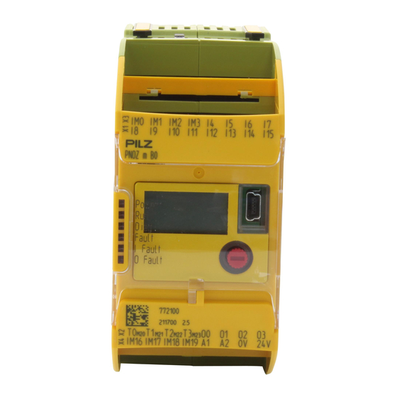
Page 9: Front View
Configurable test pulse/auxiliary outputs T0M20 ... T3M23 Semiconductor outputs O0 ... O3 Configurable inputs/outputs IM0 – IM3 Inputs I4 ... I7 Configurable inputs/outputs IM16 – IM19 Supply connections LEDs: POWER DIAG FAULT I FAULT O FAULT Operating Manual PNOZ m B0.1 1005720-EN-04... -
Page 10: Safety
Example: Protected inside space or control cabinet with protection type IP54 and appropri- ate air conditioning. Use in furnaces The product PNOZ m B0.1 can be used in furnaces in accordance with EN 298. Please note: To protect against transient power failures (EN 61000-4-11) the AC power supply used for the system must provide secondary buffering for 20 ms. -
Page 11: Applicable Documentation
EN ISO 13849 and EN IEC 62061. However, this does not guarantee the func- tional safety of the overall plant/machine. To achieve the relevant safety level of the overall plant/machine’s required safety functions, each safety function needs to be considered sep- arately. Operating Manual PNOZ m B0.1 | 11 1005720-EN-04... -
Page 12: Use Of Qualified Personnel
Adequate protection circuit must be provided for all inductive consumers. Do not open the housing or make any unauthorised modifications. Please make sure you shut down the supply voltage when performing maintenance work (e.g. exchanging contactors). Operating Manual PNOZ m B0.1 | 12 1005720-EN-04... -
Page 13: Security
Perform a risk assessment in accordance with VDI/VDE 2182 or IEC 62443-3-2 and plan the security measures with care. If necessary, seek advice from Pilz Customer Support. Required security measures The product is not protected from physical manipulation or from reading of memory con- tents during physical access. -
Page 14: Function Description
"PNOZmulti System Expan- sion". Block diagram A1 A2 IM16 IM19 Config Config Config Config Power Output Supply 0 V 24 V Operating Manual PNOZ m B0.1 | 14 1005720-EN-04... -
Page 15: Diagnostics
Locate the error source in the event of test pulse errors. For details of how to switch the test pulse outputs manually, see section entitled Switching the test pulse outputs [ 35]. Operating Manual PNOZ m B0.1 | 15 1005720-EN-04... -
Page 16: Installation
NOTICE Damage due to electrostatic discharge! Electrostatic discharge can damage components. Ensure against discharge before touching the product, e.g. by touching an earthed, conductive sur- face or by wearing an earthed armband. Operating Manual PNOZ m B0.1 | 16 1005720-EN-04... -
Page 17: Mounting Distances
Please note that at the stated minimum distance, it will be difficult to swap the chip card from above. If you cannot leave a greater distance, remove the unit from the mounting rail to swap the chip card. Operating Manual PNOZ m B0.1 | 17 1005720-EN-04... -
Page 18: Dimensions In Mm
Installation Dimensions in mm *with spring-loaded terminals Install base unit without expansion module Make sure that the terminators are inserted on the top left and right of the unit. Operating Manual PNOZ m B0.1 | 18 1005720-EN-04... -
Page 19: Connecting The Base Unit And Expansion Modules
Fit the terminator to the unconnected interfaces on the base unit and expansion module. Jumper Terminator Terminator CAUTION! Only connect the base unit and expansion modules when the supply voltage is switched off. Operating Manual PNOZ m B0.1 | 19 1005720-EN-04... -
Page 20: Commissioning
When the voltages are fed separately using two power supplies, the supply voltage for the control system and the supply voltage for the semiconductor outputs are galvanically isol- ated. CAUTION! Do not connect or disconnect expansion modules and terminators during operation. Operating Manual PNOZ m B0.1 | 20 1005720-EN-04... - Page 21 Common power supply for the supply voltage to the control sys- Supply voltage infeed tem and the supply voltage to the for the control system semiconductor outputs Supply voltage infeed for the semiconductor outputs Operating Manual PNOZ m B0.1 | 21 1005720-EN-04...
- Page 22 Input circuit without detection Input circuit with detection of of shorts across contacts shorts across contacts T0M20 Semiconductor outputs Redundant output O0 (O2) O1 (O3) Single output O0 (O2) O1 ( O3) Operating Manual PNOZ m B0.1 | 22 1005720-EN-04...
-
Page 23: Load Project From Chip Card
Download the project (see PNOZmulti Configurator's online help). Once the project has been successfully downloaded, the status of the inputs and outputs and the supply voltage will be shown on the display. The "RUN" LED will be lit. Operating Manual PNOZ m B0.1 | 23 1005720-EN-04... -
Page 24: Function Test During Commissioning
Make sure that you do not bend the chip card as you insert it into the chip card slot. To remove the chip card, press on the chip card and then pull it out. Operating Manual PNOZ m B0.1 | 24... -
Page 25: Connection Example
Commissioning Connection example Dual-channel E-STOP and safety gate wiring, monitored start (IM18), feedback loop (IM16) Operating Manual PNOZ m B0.1 | 25 1005720-EN-04... -
Page 26: Operation
The fieldbus module has not been recognised. The base unit was identified by the PNOZmulti Configur- ator via the Ethernet interface An existing fieldbus connection was interrupted. Operating Manual PNOZ m B0.1 | 26 1005720-EN-04... -
Page 27: Display Menu
Project: 2nd line: Creation date O: 06.12.2021 M: 06.02.2022 3rd line: Last changed SHOW DEVICE INFO? Show device information for Show device info? the base unit and expansion Show device information modules Operating Manual PNOZ m B0.1 | 27 1005720-EN-04... - Page 28 (PA) IP ADDRESS 2nd line: IP Address IP address of base unit 3rd line: Subnet mask (only appears on base units to which a communication module with Ethernet inter- face is connected) Operating Manual PNOZ m B0.1 | 28 1005720-EN-04...
- Page 29 Delete project from the base RESET Project? unit's memory Delete project EXIT MENU? Exit menu Exit menu? Exit menu You can switch between the menu levels by pressing or turning the knob. Operating Manual PNOZ m B0.1 | 29 1005720-EN-04...
-
Page 30: Rotary Knob
– Press the knob downwards [2] while keeping the bar pressed in 8.2.1.3 Rotate and press the knob The settings are made via the rotary knob, as follows: Press knob Confirm selection/setting Switch to menu Rotate knob Select menu level Operating Manual PNOZ m B0.1 | 30 1005720-EN-04... -
Page 31: Switch Between Menu Levels
Show Info Base Info Operating Info? Next Error Show Error Stack Stack Error Stack? IP Address Interface Reset Project? Exit Force IO Status TP Start Force Testpulse Mode? Mode Exit Menu? Error Operating Manual PNOZ m B0.1 | 31 1005720-EN-04... - Page 32 Show Next Device Base Unit Device Info? Info Operating Show Next Operating Info Base Operating Info? Info Show Error Stack Next Error Error Stack? Stack IP Address Interface Stop Device Exit Menu? Operating Manual PNOZ m B0.1 | 32 1005720-EN-04...
-
Page 33: Device Diagnostics
Error that cannot be assigned PRESSURE SENSITIVE MAT Error on the input of a pressure-sensitive PROJECT NOT RESET The project was not deleted NEW PROJECT New project detected on the chip card Operating Manual PNOZ m B0.1 | 33 1005720-EN-04... -
Page 34: Error Stack On The Lc Display
Error stack on the LC display The error stack can be read from the PNOZmulti Configurator or shown on the LC display. The error stack helps Pilz technical support with fault diagnostics. The error stack can store up to 64 status and error messages. -
Page 35: Switching The Test Pulse Outputs
In the menu, turn to the left to display the devices to the left of the base unit; turn to the right to display the devices to the right of the base unit. Left-hand expansion Right-hand expansion Base unit modules modules Operating Manual PNOZ m B0.1 | 35 1005720-EN-04... -
Page 36: Maintenance And Testing
Maintenance and testing Maintenance and testing It is not necessary to perform maintenance work on the product in normal operation. Please return any faulty products to Pilz. Operating Manual PNOZ m B0.1 | 36 1005720-EN-04... -
Page 37: Technical Details
Input voltage in accordance with EN 61131-2 Type 24 V Input current at rated voltage 5 mA Input current range 2,5 - 5,3 mA Pulse suppression 0,5 ms Maximum input delay 2 ms Operating Manual PNOZ m B0.1 | 37 1005720-EN-04... - Page 38 Voltage 24 V Current 0,1 A Max. duration of off time during self test 5 ms Short circuit-proof Potential isolation Times Simultaneity in the two-hand circuit 0,5 s Processing time 30 ms Operating Manual PNOZ m B0.1 | 38 1005720-EN-04...
- Page 39 35 x 15 EN/IEC 60715, 35 x 7,5 EN/IEC 60715 Recess width 27 mm Cable length Max. cable length per input 1 km Sum of individual cable lengths at the test pulse output 2 km Operating Manual PNOZ m B0.1 | 39 1005720-EN-04...
- Page 40 Spring-loaded terminals: Terminal points per connec- tion Stripping length with spring-loaded terminals 9 mm Dimensions Height 101,4 mm Width 45 mm Depth 120 mm Weight 220 g Where standards are undated, the 2022-05 latest editions shall apply. Operating Manual PNOZ m B0.1 | 40 1005720-EN-04...
-
Page 41: Safety Characteristic Data
SC outputs 1-channel with ad- vanced fault de- tection PL e Cat. 4 SIL 3 1,66E-11 SIL 3 1,46E-06 SC outputs 1-channel PL d Cat. 2 SIL 2 1,57E-10 SIL 2 1,35E-05 Operating Manual PNOZ m B0.1 | 41 1005720-EN-04... - Page 42 A safety function's SIL/PL values are not identical to the SIL/PL values of the units that are used and may be different. We recommend that you use the PAScal software tool to calculate the safety function's SIL/PL values. Operating Manual PNOZ m B0.1 | 42 1005720-EN-04...
-
Page 43: Classification According To Zvei, Cb24I
Max. capacitive load 126 nF Single-pole output Interfaces Source Interface Module Class Drain Interface Actuator Class C1, C2 Parameter source Max. test pulse duration 330 µs Max. rated current Max. capacitive load 1 µF Operating Manual PNOZ m B0.1 | 43 1005720-EN-04... -
Page 44: Supplementary Data
C [µF] I [A] 11.2 Maximum permitted total current of the semiconductor outputs [mA] : Total current of the configurable semiconductor outputs (auxiliary outputs) : Total current: Semiconductor outputs (safety outputs) Operating Manual PNOZ m B0.1 | 44 1005720-EN-04... -
Page 45: Maximum Permitted Humidity
Supplementary data 11.3 Maximum permitted humidity 11.3.1 Max. relative humidity, operation 11.3.2 Max. relative humidity, storage Operating Manual PNOZ m B0.1 | 45 1005720-EN-04... -
Page 46: Order Reference
Mini USB cable, 5 m 312993 Terminals Product type Features Order no. PNOZ s Set1 spring 1 set of spring-loaded terminals 751008 loaded terminals PNOZ s Set1 screw ter- 1 set of screw terminals 750008 minals Operating Manual PNOZ m B0.1 | 46 1005720-EN-04... -
Page 47: Ec Declaration Of Conformity
European Parliament and of the Council. The complete EC Declaration of Conformity is available on the Internet at www.pilz.com/downloads. Representative: Pilz GmbH & Co. KG, Felix-Wankel-Str. 2, 73760 Ostfildern, Germany Operating Manual PNOZ m B0.1 | 47... -
Page 48: Ukca-Declaration Of Conformity
2008. The complete UKCA Declaration of Conformity is available on the Internet at www.pilz.com/ downloads. Representative: Pilz Automation Technology, Pilz House, Little Colliers Field, Corby, Northamptonshire, NN18 8TJ United Kingdom, eMail: mail@pilz.co.uk Operating Manual PNOZ m B0.1 | 48... - Page 49 We are represented internationally. Please refer to our homepage www.pilz.com for further details or contact our headquarters. Headquarters: Pilz GmbH & Co. KG, Felix-Wankel-Straße 2, 73760 Ostfildern, Germany Telephone: +49 711 3409-0, E-Mail: info@pilz.com, Internet: www.pilz.com...
Need help?
Do you have a question about the PNOZ m B0.1 and is the answer not in the manual?
Questions and answers