Table of Contents
Advertisement
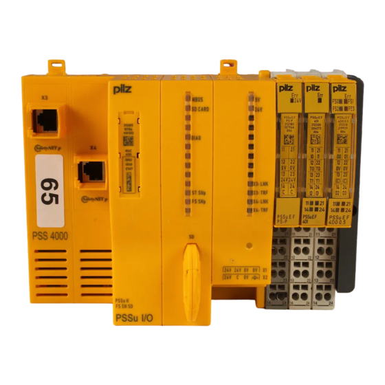
PSSu Key-in-Pocket Extended
Product
Type:
FS_KeyInPocket_SignInOut, FS_KeyInPocket_Manager, FS_KeyInPocket_BlindSpotCheck
Name:
PSS 4000, PITreader, PITgatebox, PSENmlock
Manufacturer:
Pilz GmbH & Co. KG, Safe Automation
Document
Release Number: 01
Release Date:
16 May 2023
Application Note – 1006505-EN-01
Advertisement
Chapters
Table of Contents


Need help?
Do you have a question about the PSS 4000 and is the answer not in the manual?
Questions and answers