5.3. UNPACKING 5.4. PIPING AND INSTRUMENTATION DIAGRAM 5.5. MOUNTING 5.5.1. UNIT PLACING AND MOUNTING POSITIONING REQUIREMENTS 5.5.2. CEILING-MOUNTING OF THE UNIT (SMARTY XP) 5.5.3. FLOOR MOUNTING (SMARTY XV) 5.5.4. WALL-MOUNTING OF THE UNIT (SMARTY XV) 5.5.5. DRAINAGE (SMARTY XV) 5.6. CONNECTION OF THE AIR DUCT 5.7.
Page 3
9. CONNECTION TO WIRING TERMINALS (VERSION S300) 10. ACCESSORIES SETUP (VERSION S300) 10.1. ACCESS OF CONFIGURATION PARAMETERS 10.2. HEATER 10.3. PREHEATER 10.4. SMOKE DETECTOR 10.5. FIREPLACE PROTECTION, SYSTEM MODE SWITCH OR RAPID VENTILATION SWITCH INPUT 10.6. ALARM INDICATION OUTPUT 10.7. REMOTE CONTROLLER AND KNX ROOM SENSORS 11.
2. SYMBOLS AND MARKING Warning – pay attention Additional information Apply the technical label on the unit (in an easily accessible location) or on the dashed location of the technical manual to keep the important information about the unit. Figure 2.1. Technical label 1 - Logo;...
In exceptional cases, harmful gases could be drawn out of the chimney or extraction ducting back into the room. In such case we strictly recommend to turn off Salda Antifrost and use an external preheater for heat exchanger anti-frost protection (see Salda Antifrost function in the Remote Controller Operation Manual).
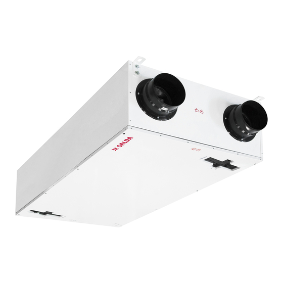
4. INFORMATION ABOUT THE PRODUCT 4.1. DESCRIPTION Smarty is the residential air handling unit with a high efficiency (up to 90%) counterflow heat exchanger. The unit supplies ventilation in home and takes the heat from exhaust air. AHU complies with ErP 2018 and Passivhaus requirements. The unit is operated by a separate remote control panel or through separate MB-Gateway by PC (version 1.1 / 1.2).
4.2. DIMENSIONS AND WEIGHT Figure 4.2.1. Smarty 2X P 1.1/1.2; Smarty 3X P / 4X P Figure 4.2.2. Smarty 2X P S300 SMARTY v2023.2 EN |...
Page 8
Figure 4.2.3. Smarty 2X V 1.1/1.2 Figure 4.2.4. Smarty 2X V S300 Figure 4.2.5. Smarty 3X V / 4X V 1.1/1.2 | EN SMARTY v2023.2...
Page 9
Figure 4.2.6. Smarty 3X V / 4X V S300 SMARTY 2X P 1.1/1.2 2X P S300 2X V 1.1/1.2 2X V S300 3X P / 4X P 3X V / 4X V [mm] 1010 1228 [mm] [mm] [mm] øD [mm] øDa [mm] [mm]...
MPL 475x134x25 Coarse 65% MPL 475x134x25 Coarse 65% LxWxH) Device protection class IP-34 IP-34 IP 34 According to EN 13141-7. Acoustic data: check the product page on www.salda.lt Not suitable for installation in living rooms: additional noise insulation required. | EN SMARTY v2023.2...
4.4. OPERATING CONDITIONS SMARTY 2X P 1.1 2X P 1.1 E 2X P 1.2 2X P 1.2 E 2X P S300 2X P S300 E Outdoor air temp. without frost protection -2 .. 40 °C -8 .. 40 °C -2 .. 40 °C -8 ..
(turning the impeller by hand) and if the electric circuit insulation is not damaged or the mois- ture has not accumulated must be performed before the installation of the unit. Figure 5.2.1. Smarty XP Figure 5.2.2. Smarty XV...
PIPING AND INSTRUMENTATION DIAGRAM Figure 5.4.1. SMARTY XP 1.1 (*Exhaust air sensor is not included with a device and should be ordered as an accessory; ** Check the manual for details; ***Not available in Smarty 2X P V1.1 units) | EN...
Page 15
Figure 5.4.2. SMARTY XP 1.2 (* Only heater or preheater can be connected at a time; ** Check the manual for details; *** Exhaust air sensor is not included with a device and should be ordered as an accessory) Figure 5.4.3.
Figure 5.4.6. SMARTY XV S300 (* Only heater or preheater can be connected at a time; ** Components connection only with PE1; *** Components connection only without PE1) THE LIST OF COMPONENTS Plate heat exchanger Supply air fan Extract air filter Supply air filter Exhaust fan Extract air temperature sensor...
The condensate tube must be filled with water as indicated during the first start-up before every heating season! α α Figure 5.5.1. Smarty XP Ceiling-mounting positions (α>1 ) (only for units with condensation heat exchanger) *The location of the condensate outlet for the specific product is indicated in the dimensional drawing α...
5.5.2. CEILING-MOUNTING OF THE UNIT (SMARTY XP) Figure 5.5.2.1. Ceiling-mounting of the unit α Figure 5.5.2.2. Drainage system installation (øD=150 mm) (only for units with condensation heat exchanger) SMARTY 2X P SMARTY 3X P / 4X P α α [mm] NOTE.
• Make sure that the fans may not be accessed through air duct heads. Otherwise, a protective grid should be installed. You may choose the grid from the range of products provided on our website https://select.salda.lt. • Do not reduce the diameter of the piping near the air inlet or exhaust ducts. If you want to reduce the airflow speed in the system, also to reduce pressure and noise level, you can increase the diameter.
Page 20
• When installing air ducts next to the ventilation equipment, brackets must be used. They suppress vibration and assure secure installation of the various system parts. The necessary brackets can be found in our catalogue or on our website https://select.salda.lt.
5.7. CONNECTION OF THE UNIT TO THE ELECTRIC NETWORK • Supply voltage to the unit must be connected by a qualified specialist following the manufacturer’s instructions and applicable safety guidelines. • The unit’s power network voltage must correspond to the electro-technical specifications of the unit indicated in the technical decal.
6. MAINTENANCE 6.1. SAFETY INSTRUCTION Unplug the unit from the mains before opening the door (disconnect the power plug from the outlet or in case a two-pole automatic circuit breaker is installed, disconnect it as well. Make sure that it cannot be turned on by the third parties) and wait until the fans completely stop (for about 2 min.).
• In order to remove the filters, open filter cover by pulling the strap and take out the filters. Use Coarse 65% filters or optionally the ePM1 70% filter for outdoor air filtration and the Coarse 65% filter for the exhaust air filtration. • Dirty filters increase air resistance, this decreases the airflow into the rooms. Figure 6.4.1. Smarty XP Figure 6.4.2. Smarty 2X V Figure 6.4.3.
Prior to commencing any maintenance or repair works, make sure the unit is disconnected from the power source. SMARTY XP (version 1.1 / 1.2): • Remove the fan connectors from the control board. Supply air fan connects to X15, X2, X4 connectors. Extract air fan connects to X16, X2, X4 connectors.
Page 25
SMARTY XP (version S300): • Disconnect cable wires of supply and extract air fans from control board. Fans control signals connect to T2 and T18 controller terminals. Fans power signals connect to XP1 terminal blocks. SMARTY 2/3X V (version S300): •...
Figure 6.6.7. Smarty 2X P NOTE. Prior to performing steps in Figure 6.6.7, steps in Figure 6.3.1 (1-3) and Figure 6.5.1 (1-4) / Figure 6.5.2 (1-2) should be carried out. Figure 6.6.8. Smarty 3X P / 4X P NOTE. Prior to performing step in Figure 6.6.8, steps in Figure 6.3.2 and Figure 6.5.4 (1-3) should be carried out. Figure 6.6.9.
Page 27
Smarty XP bypass damper Figure 6.7.2. Smarty XP S300 bypass damper SMARTY XV (version 1.1 / 1.2): • If the manual protection is activated, check for a fault before pressing the RESET button. If the fault is identified after it has been rectified, press the RESET button using a screwdriver or similar object.
Smarty 3X V / 4X V S300 6.8. CONTROL BOARD MAINTENANCE SMARTY XP: • Loosen the front screw that tightens the automation sole to the housing of the device. • Disconnect all necessary cables, wires, connectors and pressure hoses for control board removal.
Page 29
Figure 6.8.4. Smarty 3/4X P S300 SMARTY XV (version 1.1 / 1.2): • Unscrew the front bolt securing the control board holder to the unit casing. • Withdraw the automation through the front part. • Disconnect the connectors from the control board. •...
1. Selected control interface (remote control panel, MB-GATEWAY, etc.). The selected interface affects access to the information and settings, however, it does not affect the logic of control. Full access to the information and settings is available on ST-SA-Control, MB-GATEWAY WEB application and SALDA AIR mobile application. 2. Unit configuration (internal/external components, sensors and control board settings).
8. CONNECTION OF ACCESSORIES 8.1. HEATER AND PRE-HEATER 8.1.1. VERSION 1.1 Smarty 1.1 units feature one connection for external electrical air heater and one for external air pre-heater. Pre-heater is integrated inside the product. Heater/pre-heater can be controlled by the following signals: •...
Page 32
EKA NIS connection: Automatic and manual protection devices must be connected to EX1 controller ‘s X23 connector when an electric heater is equipped with these connection terminals. Otherwise, jumpers are installed on the X23 connector protection inputs. Automatic and manual protection devices must be connected to the controller’s X5 connector when an electric pre-heater is equipped with these connection terminals.
8.1.2. VERSION 1.2 Smarty 1.2 units feature one connection of external electrical heater/pre-heater. In factory settings, the connection is intended for the pre-heater, however, it can be configured for the heater. Heater/pre-heater can be controlled by the following signals: • 0-10V – EKA NIS •...
Page 34
EKA NIS connection: Automatic and manual protection devices must be connected to the controller’s X5 connector when an electric heater/pre-heater is equipped with these connection terminals. Otherwise, jumpers are installed on the X5 connector protection inputs. | EN SMARTY v2023.2...
Page 35
Since the pre-heater must be connected according to the factory settings, the settings should be changed in the environment of the MB-Gateway WEB application service or on the ST-SA-Control panel. SETTINGS IN THE ENVIRONMENT OF THE MB-GATEWAY WEB APPLICATION SERVICE Change the settings as follows: •...
Mini MCB When using the supply air heater, the supply air sensor (TJ) must be installed downstream the heater (or cooler) at the length of sensor cable allows or up to the first branching or bend of air transportation system. Only heaters with up to 0.6 kW power circuit can be connected directly to the control board.
Preheater Input Digital/NTC10k Output digital relays 24-230 V AC, max 6.3A, normally open/closed (in reference to GND) Output 0-10V Air temperature sensor after preheating coil Preheating coil position Electric preheating coil command Input Digital/NTC10k Input Digital/NTC10k (in reference to GND) (in reference to GND) Preheating coil overtemperature detector Outside air temperature sensor...
8.4. EXTERNAL CO /RH SENSORS (VERSION 1.1 / 1.2) Smarty XP 1.1 / Smarty XV 1.1 units feature two connections for external CO /RH (input 0-10VDC) sensors. Sensors connection: Smarty 3X V 1.1 and Smarty 4X V F2 1.1 come with the integrated RH sensor connected.
8.6. CONCENTRATION ACCORDING TO PETTENKOFER LIMIT 8.7. CONNECTION OF SUPPLY AND EXHAUST AIR DAMPERS (VERSION 1.1 / 1.2) All versions of Smarty can be equipped with outdoor air and exhaust air dampers. Dampers are operated by Open/Close actuators. Installation diagram See "PIPING AND INSTRUMENTATION DIAGRAM".
Output digital relays 24-2 Output digital relay 24-230 V AC, max 6.3A, normally open/closed normally open/closed Air Handling unit can be controlled with remote control panel POS8. Remote controller connects with S300 controller via KNX PL-Link interface. T15:1;2 – terminals of AHU’s controller for KNX devices. Same interface and controller terminals are used for QMX3 room sensors P30, P40 and P70 connection.
Modbus slave port1 over KNX PL-Link, galvanic RS485, HMI/RU interface isolation, 40mA rated NO/NC switch To air quality sensor Modbus RTU or remote controller +24VDC Connected by user Figure 8.11.1. D2 digital input connection After connection, configuration has to be performed. For more information see section "ACCESSORIES SETUP (VERSION S300)". Date 2022-01-17 EPLAN...
8.15. RECOMMENDED SCHEMES FOR CONNECTION OF INTERNAL AND EXTERNAL COMPONENTS *Only Smarty 1.1 versions have N2 module. Figure 8.15.1. SMARTY XP 1.1/1.2; Smarty 2X V 1.1; Smarty 2X V / 3X V / 4X V F2 1.2 (219.1017.0.1.1-PS) | EN...
Page 43
Figure 8.15.2. SMARTY XP 1.1/1.2; Smarty 2X V 1.1; Figure 8.15.3. SMARTY XP 1.1/1.2, Smarty 2X V 1.1; Smarty 2X V / 3X V / 4X V F2 1.2 (219.1017.0.1.2-PS) Smarty 2X V / 3X V / 4X V F2 1.2 (219.1017.0.1.3-PS) Figure 8.15.4.
Page 44
KF2EDGKD-2.5/8P -X3 KF2EDGKD-2.5/6P Bypass actuator Bypass position switch Figure 8.15.5. Bypass wiring (version 1.1 / 1.2) (221.1055.0.1.0-PS) DUTIES / NAME SIGNAT 221.1055.0.1.0-PS EI A. Šklenikas DRAWN BY EI D. Aleksandravičius CHECKED BY Principal electrical connection scheme CHECKED BY Figure 8.15.6. Preheater, Bypass wiring (Smarty 3XV-PE-0k) | EN SMARTY v2023.2...
Page 45
Figure 8.15.7. Preheater (SP35) miniMCB V0.3 miniMCB V0.3 miniMCB V0.3 miniMCB V0.3 Smarty 4X P F2 unit fans connect to controller with different color exten- sion wires Smarty 4X V F2 unit fans connect to controller with extension wires through X32/X33 connectors Cable for power supply Cable for control Cable for power supply...
Page 46
Figure 8.15.9. External preheater (version 1.1 / 1.2) (SP45) Figure 8.15.10. Smarty 3X V / 4X V F2 1.1 (219.1349.0.1.1-PS) | EN SMARTY v2023.2...
Page 47
Figure 8.15.11. Smarty 3X V / 4X V F2 1.1 (219.1349.0.1.2-PS) Figure 8.15.12. Smarty 3X V / 4X V F2 1.1 (219.1349.0.1.3-PS) SMARTY v2023.2 EN |...
Page 48
Figure 8.15.13. Smarty XP version S300 (power and fans) Figure 8.15.14. Smarty XP version S300 (sensors and bypass) | EN SMARTY v2023.2...
10. ACCESSORIES SETUP (VERSION S300) Some accessories or functions of connected external components must be additionally configured to work properly in the Air Handling unit’s system. Configuration is performed via ABT Go application which can be found on play.google.com/store/apps. 10.1. ACCESS OF CONFIGURATION PARAMETERS To access configuration parameters follow these steps: •...
10.2. HEATER In order to control electrical heater, it has to be configured by following steps: • In CONFIGURATION window select ONLINE CONFIGURATION BASIC and press OK on warning. Wait for the device to switch in configuration mode. • Set HEATING COIL parameter to ELECTRIC HEATING COIL 21Y. •...
10.6. ALARM INDICATION OUTPUT By default, indication output is configured to indicate if any type of unit’s alarm (A or B) is triggered. It is possible to reconfigure output to indicate triggered only B type alarm, only: • In CONFIGURATION window select ONLINE CONFIGURATION EXTENDED and press OK on warning. Wait for the device to switch in configuration mode. •...
LST EN 61000-6-4:2007/A11:2011 - Electromagnetic compatibility (EMC) .Part 6-4: Generic standards - Emission standard for industrial environ- ments. Should any alterations be made in the products, this declaration will no longer apply. Quality: SALDA UAB activities are in line with the international quality management system standard ISO 9001:2015. Date 2022-05-17...
3.4. when the unit was used not for its original purpose. 3.5. Company SALDA UAB is not responsible for potential loss of property or personal injury in cases where the Air Handling unit is manufactured without the control system and the control system is installed by the client or the third parties. The manufacturer’s warranty does not cover devices that will be damaged by installing the control system.
Page 60
** - At least. NOTE. The customer shall be required to complete the Product Maintenance Table. LINKS TO OTHER DOCUMENTS AHU’S CONTROLLER (S300) ROOM OPERATOR UNIT POS8 DE MANUAL DK MANUAL FR MANUAL https://select.salda.lt/file/ https://select.salda.lt/file/ https://select.salda.lt/file/ https://select.salda.lt/file/ https://select.salda.lt/file/ siemens-climatix-s300en siemens-room-opera- smarty-de...
Need help?
Do you have a question about the SMARTY XP and is the answer not in the manual?
Questions and answers