Salda AMBERAIR COMPACT S-CX H Operation, Installation & Maintenance Instructions
Source: salda.lt/en, vetter-lufttechnik.de
Table of Contents
Advertisement
Quick Links
Advertisement
Table of Contents

Related Manuals for Salda AMBERAIR COMPACT S-CX H


Summary of Contents for Salda AMBERAIR COMPACT S-CX H
- Page 1 AMBERAIR COMPACT S-CX H/V OPERATION, INSTALLATION & MAINTENANCE INSTRUCTIONS...
-
Page 2: Table Of Contents
1. CONTENTS 1. CONTENTS 2. SAFETY INSTRUCTIONS AND PRECAUTIONS 2.1. SAFETY SWITCH 2.2. DANGERS AND RISKS OF INJURY 2.3. SAFETY GUARDS 3. GENERAL PART 3.1. RANGE OF APPLICATION 3.2. PRODUCT INFORMATION 3.3. SYMBOLS AND MARKING 3.4. VERSIONS AND FAN ARRANGEMENT 3.4.1. - Page 3 5.5.4. EXTERNAL HEATER, COOLER (COIL2) 5.5.5. EXTERNAL PREHEATER (COIL3) 5.5.6. AIR QUALITY SENSORS WITH ANALOG OUTPUT 5.5.7. CUSTOM SWITCHES 5.6. OPERATING THE UNIT 5.6.1. ST-SA-CONTROL REMOTE CONTROL PANEL AND SALDA AIR APP 5.6.2. WEB INTERFACE 6. MAINTENANCE 6.1. MAINTENANCE INTERVALS 6.2. OPENING THE DOOR 6.3.
-
Page 4: Safety Instructions And Precautions
Such changes will be included in the new issues of the technical passport. All illustrations are just for information and thus may differ from the original device. The newest manual version is available at https://select.salda.lt 2. SAFETY INSTRUCTIONS AND PRECAUTIONS Read these instructions very carefully before installing and using this equipment. -
Page 5: General Part
3.2. PRODUCT INFORMATION This manual includes the information required for installing and maintaining the heat recovery unit type AmberAir Compact S manufactured by SALDA UAB. The units include the following model options: AmberAir Compact S-CX-1500-H-E-R-C1 C1 - Control options are CAV (C1) -
Page 6: Versions And Fan Arrangement
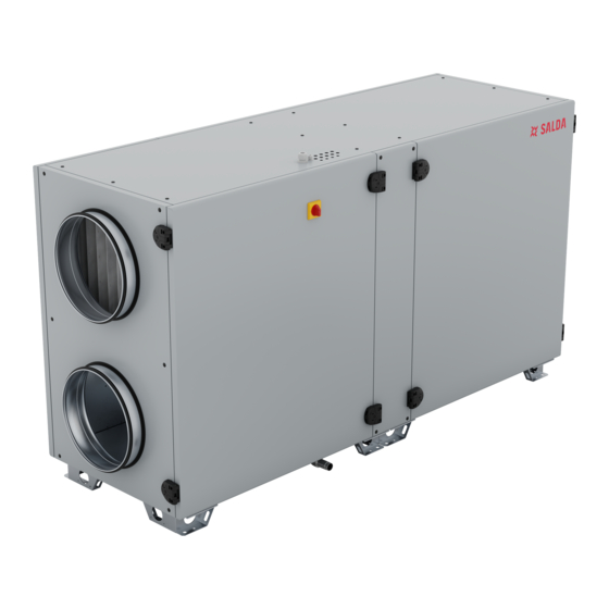
NOTE. Ducts are not parts of the unit. 3.4. VERSIONS AND FAN ARRANGEMENT The safety power switch is located on unit casing. Fig. 3.4.1 AmberAir Compact S-CX H (left version) Fig. 3.4.2 AmberAir Compact S-CX H (right version) Fig. 3.4.3 AmberAir Compact S-CX V (left version) Fig. -
Page 7: Mechanical Design
Air handling units are designed to provide ventilation in premises and depending on settings, passive heat recovery, air heating or “free cooling”. Sound levels exceeding 60 dB(A) may occur depending on load and unit size (see select.salda.lt for detailed information). - Page 8 X18 MCB connector is for the Remote controller. X19 MCB connector is for BMS. S1 DIP switch is for X19. Switch Position Purpose 120 Ohm termination load (On/Off) 1 kOhm RS line pull-up (On/Off) 1 kOhm RS line pull down (On/Off) | EN AMBERAIR COMPACT S-CX v2023.3...
-
Page 9: Installation
4. INSTALLATION 4.1. GENERAL Personnel must be trained before starting to use the unit. Any damages to the unit or its components are not covered by warranty if the require- ments are not fulfilled. The product identification labels are located on the inspection side of the air handling unit. The air handling unit is supplied in a special package. -
Page 10: Unpacking
4.6. STANDARD PACKAGE OF COMPONENTS The separately packaged components of the unit, the condensate drain Elbow 90° and the condensate connection pipe are in the box and placed inside the product. AmberAir Compact S-CX H AmberAir Compact S-CX V Key L-shape Elbow 90°... - Page 11 On the installation side, there must be enough place (1.5x product depth) for the door to open for service (replacing filters, removing the fan, cleaning the heat exchanger, etc.). • Installation works should be carried out by qualified and trained staff only. •...
-
Page 12: Roof Mounting (Accessory)
• When installing air ducts next to the ventilation equipment, brackets must be used. They suppress vibration and assure secure installation of the various system parts. The necessary brackets can be found in our catalogue or on our website https://select.salda.lt. -
Page 13: Supply Air Temperature Sensor Installation
4.10. SUPPLY AIR TEMPERATURE SENSOR INSTALLATION The supply air temperature sensor is equipped with a B-meter-long cable. The sensor is connected to the X5:1 and X5:2 terminals of MCB control- ler. In order for the air handling unit to work properly, the supplied air temperature sensor must be installed inside the supply air duct. The minimum distance at which the sensor must be installed from the unit is A meters. -
Page 14: Connecting Water Coils
4.12. CONNECTING WATER COILS Only a specially trained employee may connect the air handling unit to the heating or cooling system. When connecting the coil nozzles to the system, they must be fixed in place with a pipe wrench. The coil pipes must be connected in such a way that the pipes can be easily accessed during maintenance works. When installing the coil pipes, make sure that the heat carrier supply is completely disconnected. -
Page 15: System Protection
N(8) N(8) N(8) N(8) PE(2) PE(2) PE(2) PE(2) PE(1) PE(1) PE(1) PE(1) N(7) N(7) N(7) N(7) User side User side User side User side Fig. 4.13.1 Units with 1N~ 230V power supply Fig. 4.13.2 Units with 3N~ 400V power supply •... -
Page 16: Connection Of Accessories
Spring back Spring back Book # DUTIES / NAME SIGNATURE DATE DUTIES / NAME SIGNATURE DATE Air dampers (Electrical unit) UAB"SALDA" EI O. Drąsutis 2023-03-27 DRAWN BY EI O. Drąsutis UAB"SAL 2023-03-27 DRAWN BY Drawing # EI D. Aleksandravičius 2023-03-27 CHECKED BY EI D. -
Page 17: Fire And Fireplace Safety (Safety Inputs, Dampers)
4.16.2. FIRE AND FIREPLACE SAFETY (SAFETY INPUTS, DAMPERS) Product AmberAir Compact can be equipped with fire dampers for extract and supply air. Dampers are controlled by Spring-return actuators (A1, A2). Upon activation of signals EX2 DO1 and EX2 DO2 the dampers shall open. When EX2 DO1/DO2 is deactivated, the dampers shall close. -
Page 18: External Heater, Cooler (Coil2)
4.16.3. EXTERNAL HEATER, COOLER (COIL2) For AmberAir Compact units without an integrated combined heating/cooling coil, it is possible to connect the external DX cooler and external combined heating/cooling coil. For units with integrated combined heating/cooling coil, it is possible to connect an external DX cooler and the external water heater. These components are controlled with DO and 0-10V outputs. - Page 19 Valve sensor actuator Fig. 4.16.3.2 External combined heating/cooling coil connection DUTIES / NAME SIGNATURE DATE Hydraulic cooler/heater EI O. Drąsutis UAB"SALDA" 2023-03-27 DRAWN BY ons wired by the user EI D. Aleksandravičius 2023-03-27 CHECKED BY Connections principal scheme 2023-03-27 APPROVED BY MCB_V2.0...
-
Page 20: External Preheater (Coil3)
4.16.4. EXTERNAL PREHEATER (COIL3) For AmberAir Compact units it is available to connect electrical or water preheater. These components are controlled with DO and 0-10V outputs. When digital output EX2 DO11 activates, the external device (electrical preheater or water circulation pump) should start. When digital output deactivates, the external device should stop. Analog output EX1 AO1 electrical preheater or water valve actuator control signal. -
Page 21: Air Quality Sensors With Analog Output
Fig. 4.16.4.2 External water preheater connection DUTIES / NAME SIGNATURE DATE Hydraulic preheater 4.16.5. AIR QUALITY SENSORS WITH ANALOG OUTPUT EI O. Drąsutis UAB"SALDA" 2023-03-27 DRAWN BY Connections wired by the user EI D. Aleksandravičius 2023-03-27 CHECKED BY Connections principal scheme 2023-03-27 Two air quality sensors with 0-10VDC output may be connected to the AmberAir Compact unit. -
Page 22: Integrated Water Heater Or Combined Heating/Cooling Coil
4.16.6. INTEGRATED WATER HEATER OR COMBINED HEATING/COOLING COIL The water circulation pump and valve actuator can only be connected to the AmberAir Compact units that are designed to operate with the internal water heater or combined heating/cooling coil. The position of the valve actuator with 24VDC power input is controlled by the 0-10VDC signal (MCB AO3 for water heater; EX1 AO3 for combined heating/cooling coil). - Page 23 EX2 V1.0 EX1 V2.0 EX1 V2.0 MCB_V2.0 0-10 VDC 24VDC Reverse thermostat Valve Circ. pump actuator DUTIES / NAME SIGNATURE DATE Fig. 4.16.6.2 Internal combined heating/cooling coil accessories connection Water cooler/heater accesories EI O. Drąsutis 2023-06-30 DRAWN BY Connections wired by the user EI D.
-
Page 24: External Indication Outputs And Custom Switches
50mA max. 50mA 1.2W 1.2W acturer Book # DUTIES / NAME SIGNATURE DATE Digital inputs and outputs EI O. Drąsutis UAB"SALDA" 2023-03-27 DRAWN BY Drawing # EI D. Aleksandravičius 2023-03-27 CHECKED BY Connections principal scheme 2023-03-27 APPROVED BY | EN... -
Page 25: Commissioning
5. COMMISSIONING 5.1. GENERAL • The unit may be commissioned only by properly educated and trained personnel and in compliance with all the relevant safety regulations and standards. • Prior to putting the unit into operation for the first time, it is necessary to complete each previous step of the installation instructions. •... -
Page 26: Change Of Fans Control Type
DESCRIPTION OF SERVICING OPERATION COMMENT Other operation: 5.3. CHANGE OF FANS CONTROL TYPE AmberAir Compact units come from the factory already controlled by constant air flow. Units can be converted to control fans by constant air pressure or by percentage. Converting to constant air pressure control type: •... - Page 27 • Connect new hoses to the sensor adapters. Route hoses to the outside of the unit through the upper grommets and mount them as shown below. Fig. 5.3.1 Vertical Right units AMBERAIR COMPACT S-CX v2023.3 EN |...
-
Page 28: Pressure Switch Setting
After installation of the pressure hoses, the controller of the unit must be configured for controlling fan speed by constant air pressure. Configura- tion can be implemented using the web interface, SALDA AIR mobile application or ST-SA-Control remote panel. • Go to the unit’s controller configuration parameters (see section ”ACCESS OF CONFIGURATION PARAMETERS”). -
Page 29: Accessories Setup
• Connect to your WIFI access point. • Start the SALDA AIR application and access your unit automatically or manually (units SLAVE ID by default – 1; MB-Gateway PORT and IP depends on its configuration; adjuster password by default – 1111). -
Page 30: External Heater, Cooler (Coil2)
To change default actions of custom switches activation: • For the ST-SA-Contol or SALDA AIR app in the SERVICE menu select MAIN. For the web interface in the ADJUSTER menu select USER SETTINGS. • Set preferred SYSTEM MODE SWITCH parameters. -
Page 31: Operating The Unit
(connection can be automatic or manually chosen). Adjuster’s user password by default – 1111. SALDA AIR is a mobile application (may be downloaded from Google Play Store or Apple App Store) that allows users to control AmberAir Com- pact units using a Smartphone or tablet. - Page 32 Fig. 5.6.1.3 ST-SA-Control and SALDA AIR system mode screen view ICON LABEL DESCRIPTION STANDBY 1 Options: BUILDING PROTECTION 2 • BOOST TIMER Options: ECONOMY 3 • BOOST TIMER Options: COMFORT 4 • BOOST TIMER BOOST TIMER 5 To change temperature setpoint on the remote controller or mobile application, press SETPOINT on the main screen ant select desired temperature.
-
Page 33: Web Interface
5.6.2. WEB INTERFACE The AmberAir Compact units can also be controlled using a computer. When the air handling unit is connected to a local network (via an additional device – MB-Gateway), a computer of the same network can access the unit. Fig. -
Page 34: Maintenance
6. MAINTENANCE Unplug the unit from the mains before opening the door (disconnect the power plug from the outlet, or in case an automatic circuit breaker is installed, disconnect it as well. Make sure that it cannot be turned on by the third parties) and wait until the fans completely stop (for about 2 min.). -
Page 35: Opening The Door
(approximately 2 min.). It necessary to assure, that the main switch cannot be turned on by the third parties. Fig. 6.2.1 AmberAir Compact S-CX V Fig. 6.2.2 AmberAir Compact S-CX H 6.3. FILTER REPLACEMENT Filters must be replaced when their clogging is indicated on any of the unit’s control environment’s. -
Page 36: Fans Maintenance
• If necessary, the heat exchanger can be treated with a disinfectant or antibacterial agent, which is suitable for cleaning and disinfecting alumin- ium and plastic. Fig. 6.4.1 AmberAir Compact S-CX V Fig. 6.4.2 AmberAir Compact S-CX H 6.5. FANS MAINTENANCE Fans get dirty, which reduces their efficiency. -
Page 37: Water Coil Maintenance
• If necessary, the electric heater can be removed. Disconnect the electrical connector from the heater and remove the heater. Fig. 6.6.1 AmberAir Compact S-CX V Fig. 6.6.2 AmberAir Compact S-CX H 6.7. WATER COIL MAINTENANCE It is recommended to check the condition of the coil periodically and clean it. Check that the coil plates are not folded and that the seal is tight. -
Page 38: Troubleshooting
7. TROUBLESHOOTING 7.1. SYSTEM NOTIFICATIONS The system notifies the user about the failures by warnings that are cancelled automatically and by alarms that have to be cancelled manually. It is recommended that the alarms are cancelled by a specialist prior to detection of the causes of the alarm. Information about alarms/warnings is displayed on a particular unit’s control environment’s main window. -
Page 39: Technical Data
8. TECHNICAL DATA 8.1. DIMENSIONS ØD Fig. 8.1.1 AmberAir Compact S-CX H-L-C1 dimensions Fig. 8.1.2 AmberAir Compact S-CX H-R-C1 dimensions AMBERAIR COMPACT S-CX v2023.3 EN |... - Page 40 Fig. 8.1.3 AmberAir Compact S-CX H-CO-L-C1 dimensions D out D in Fig. 8.1.4 AmberAir Compact S-CX H-CO-R-C1 dimensions | EN AMBERAIR COMPACT S-CX v2023.3...
- Page 41 AMBERAIR 1000-H- 1000-H- 1000-H- 1000-H- 1000-H- 1000-H- 1500-H- 1500-H- 1500-H- 1500-H- 1500-H- 1500-H- COMPACT S-CX L-C1 R-C1 E-L-C1 E-R-C1 CO-L-C1 CO-R-C1 L-C1 R-C1 E-L-C1 E-R-C1 CO-L-C1 CO-R-C1 [mm] 1 765 1 845 2 300 2 375 [mm] [mm] 1 195 ØD [mm] [mm]...
- Page 42 Ødn Ødn ØD dout Fig. 8.1.5 AmberAir Compact S-CX V-L-C1 dimensions dout Fig. 8.1.6 AmberAir Compact S-CX V-R-C1 dimensions | EN AMBERAIR COMPACT S-CX v2023.3...
- Page 43 AMBERAIR 1000-V- 1000-V- 1000-V- 1000-V- 1000-V- 1000-V- 1500-V- 1500-V- 1500-V- 1500-V- 1500-V- 1500-V- COMPACT S-CX L-C1 R-C1 E-L-C1 E-R-C1 W-L-C1 W-R-C1 L-C1 R-C1 E-L-C1 E-R-C1 W-L-C1 W-R-C1 [mm] 1 350 2 000 [mm] [mm] 1 200 1 600 ØD [mm] [mm] [mm] [mm]...
-
Page 44: Connection To Wiring Terminals
8.2. CONNECTION TO WIRING TERMINALS MCB: | EN AMBERAIR COMPACT S-CX v2023.3... - Page 45 WIRING TERMINALS TYPE FUNCTION X1: 1,3 Cathode X1: 2,4 Anode X2: 1,2,3,4 Holo input and power X3: 1 Digital input (NO/NC) Electrical heater auto protection/combined heating cooling coil reverse X3: 3 Digital input (NO/NC) Electrical heater manual protection/water heater protection X3: 5 Digital input (NO/NC) Supply fan protection...
- Page 46 EX1 module: | EN AMBERAIR COMPACT S-CX v2023.3...
- Page 47 WIRING TERMINALS TYPE FUNCTION X20: 1,2,3 Power 24VDC power supply for water preheater actuator X20: 4,5,6 Power 24VDC power supply for water cooler actuator X21: 1 Digital input (NO/NC) Electrical preheater aut. protection X21: 3 Digital input (NO/NC) Electrical preheater man. protection X21: 5 Digital input (NO/NC) System mode switch...
- Page 48 EX2 module: WIRING TERMINALS TYPE FUNCTION X32: 1 230VAC digital output (max 100mA) Fire damper actuator 1 open X32: 4 230VAC digital output (max 100mA) Fire damper actuator 2 open X32: 2,5 Neutral Neutral contact for digital output ref. X32: 3,6 Earth Earth contact for the damper actuators X33: 1...
-
Page 49: Electrical Data
WIRING TERMINALS TYPE FUNCTION X41: 1,2 Digital output DX cooler start X42: 1 230VAC digital output Electrical preheater starts/water preheater circulation pump starts X42: 2 Neutral Neutral contact for digital output ref. X42: 3 Earth Earth contact for the circulation pump X43: 1,2,3 Power 230VAC power supply for X42... -
Page 50: Filter Data
-ETA Remote control panels: 0-10V sensors: - ST- SA control - CO2 - Stouch - RH With MB - GATEWAY: - SALDA AIR U4(f) U3(f) - Web interface - BMS over Modbus TCP/IP Coil1 Coil2 - BMS over BACnet IP... - Page 51 Remote control panels: 0-10V sensors: - ST- SA control - CO2 - RH - Stouch With MB - GATEWAY: U4(f) U3(f) - SALDA AIR - Web interface - BMS over Modbus TCP/IP Coil1 Coil2 - BMS over BACnet IP -SUP -EHA U3(p)*...
- Page 52 * U3(p) and U4(p) are converted from U3(f) and U4(f) to control fan speed by constant air pressure; ** Coil2 accessories from SALDA are only suitable for mounting in horizontal duct position; *** Water heater thermostat (T1) is only equipped with water heater (HW1)
- Page 53 List of integrated components Availability List of optional accessories Availability Air fan supply Heating/cooling coil combined Two for single Air Handling Air fan exhaust Heater water unit (depends Air filter outdoor Cooler DX on version) Air filter extract Preheater electrical One for single Air Handling Differential pressure switch for OF...
-
Page 54: Appendices
Casing sound power level [dB(A)] ERP compliance 2018 2018 2018 2018 2018 2018 Internet address https://select.salda.lt AMBERAIR COMPACT S-CX PRODUCT NAME 1500-H 1500-H-E 1500-H-CO 1500-V 1500-V-E 1500-V-W Topology Bidirectional Bidirectional Bidirectional Bidirectional Bidirectional Bidirectional... -
Page 55: The Components Of The Air Handling Units
All the individual components are specified below in a simplified and diagrammatical description. Fig. 9.2.1 AmberAir Compact S-CX V Fig. 9.2.2 AmberAir Compact S-CX H 1 - Plate heat exchanger; 2 - Exhaust fan; 3 - Supply fan; 4 - By-pass damper; 5 - Electrical/water coil;... - Page 56 Fig. 9.3.2 AmberAir Compact S-CX H 1 - Doors (metal and insulation); 2 - Front middle panel (metal and insulation); 3 - Control (electronic); 4 - Filter (metal and media); 5 - Heat exchanger (aluminium); 6 - Heater (metal and electronic); 7 - Fan (Metal, plastics and electronic);...
-
Page 57: Declaration Of Conformity
Should any alterations be made in the products, this declaration will no longer apply. Notifi ed body: VšĮ Technikos priežiūros tarnyba, Naugarduko g. 41, LT – 03227 Vilnius, Lithuania, identifi cation number 1399. Quality: SALDA UAB activities are in line with the international quality management system standard ISO 9001:2015. Date... -
Page 58: Warranty
3.4. when the unit was used not for its original purpose. 3.5. Company SALDA UAB is not responsible for potential loss of property or personal injury in cases where the Air Handling unit is manufactured 3.5. Company SALDA UAB is not responsible for potential loss of property or personal injury in cases where the Air Handling unit is manufactured without the control system and the control system is installed by the client or the third parties. - Page 59 AMBERAIR COMPACT S-CX v2023.3...
- Page 60 LINKS TO OTHER DOCUMENTS MCB_MINIMCB MANUAL MB-GATEWAY QUICK LAUNCH ST-SA CONTROL MANUAL ST-SA CONTROL QUICK GUIDE LAUNCH GUIDE https://select.salda.lt/file/mcb- https://select.salda.lt/file/mb- https://select.salda.lt/file/ https://select.salda.lt/file/sac- minimcben gatewayen sa-control ontrolqlg DE MANUAL DK MANUAL FR MANUAL IT MANUAL LT MANUAL https://select.salda.lt/file/ambe- https://select.salda.lt/file/ambe- https://select.salda.lt/file/ambe- https://select.salda.lt/file/ambe- https://select.salda.lt/file/ambe-...
Need help?
Do you have a question about the AMBERAIR COMPACT S-CX H and is the answer not in the manual?
Questions and answers