Table of Contents
Advertisement
Advertisement
Table of Contents

Related Manuals for Hamilton Air 5000 Series

Summary of Contents for Hamilton Air 5000 Series
- Page 1 5000 Series Audio/Video System Installation & Service Manual 08-315 (3/6/12)
-
Page 2: Table Of Contents
Table of Contents Description..................3 System Configuration................3 Cable Considerations.................4 Matrix Installation................4 Matrix / System Wiring Diagram............5 Lane Speaker/Driver Kit Installation..........6 Cat 5 Lane Speaker/Driver Kit Installation........7 Wireless Headset Installation.............8 E10052 Wireless Expansion Adapter..........9 5512 Remote Handset Installation.............9 5012 Remote Handset Installation...........11 5570/5571 Remote Customer Audio Consoles........12 5572/5573 Remote Customer “In Wall”... -
Page 3: Description
Description The 5000 Series system consists of components that allow 2-way audio and video communications between server (teller) consoles and customer units in banks, pharmacies and other service environments. These systems allow both parties to hear and speak at the same time without feedback. -
Page 4: Cable Considerations
Cable Considerations Be sure to use the proper cable for connecting the matrix to the customer lanes. For audio it is HIGHLY RECOMMENDED to use Hamilton cable (E0680) for distances up to approximately 180 feet. This cable contains a 16AWG twisted pair for the speaker, a 20AWG twisted pair for the call button and a 20AWG twisted, shielded pair for the microphone. -
Page 5: Matrix / System Wiring Diagram
Matrix / System Wiring Diagram Refer to Figure 2 for standard wiring connections. The drawing shows a 4-lane matrix but the same wiring applies to all versions. Observe the following guidelines. The ground wire connection shown for the audio matrix is not required for the 5003 matrix. Be sure to only connect the drain wire for the microphone pair at the matrix end as shown. -
Page 6: Lane Speaker/Driver Kit Installation
Lane Speaker/Driver Kit Installation The Lane Speaker Driver Kit (E0892-KIT) is discontinued and is replaced by the E0958-KIT shown on the next page. The E0958-KIT can be used with standard audio cable or Cat 5 cable. The E0892-KIT is shown here for existing service purposes only. Audio cable from the matrix to the customer lane is typically limited to approximately 180 feet with 16AWG speaker wire due to the resistance of the wire. -
Page 7: Cat 5 Lane Speaker/Driver Kit Installation
Cat 5 Lane Speaker/Driver Kit Installation The Cat 5 Lane Speaker Driver Kit (E0958-KIT) allows for the use of Cat 5 cable from the matrix to the customer lane for distances up to 1000 feet. Cat 5e & Cat 6 may also be used. This kit can also be used with standard E0680 audio cable to correct problems caused from excessive cable length. -
Page 8: Wireless Headset Installation
Wireless Headset Installation The following instructions apply to the Plantronics CS50 & CS55 Wireless Headsets. There are many other wireless headsets on the market and many of these will most likely work fine with this system but compatibility cannot be guaranteed. Wireless headsets can be used on 5501, 5001 & 4001 Series consoles. -
Page 9: E10052 Wireless Expansion Adapter
(wall mount) and 5012H (side mount) handsets. It provides customer privacy and can be used with 3000, 4000 and 5000 Series audio systems. The only operational difference is removing the handset of the 5512 from its cradle does not initiate a Teller Call like the 5012 did;... - Page 10 The Model 5512 can be wall mounted or mounted to the side of pneumatic tube drive-up units if desired. Handsets that are used outdoors should be protected from direct rain. Installation 1) Remove the 4 screws from the lid of the enclosure. This makes mounting the enclosure easy since the entire contents are removed with the lid.
-
Page 11: 5012 Remote Handset Installation
5012 Remote Handset Installation The 5012 Remote Handset has been replaced with the 5512 but is described here for service purposes. With the 5012, removing the handset from its cradle initiates a Teller Call and disconnects the remote station speaker and microphone. The 5012 is equipped with a hearing-aid compatible receiver. Important Note: The handset used with the 5012 is different from the 5512 handset. -
Page 12: 5570/5571 Remote Customer Audio Consoles
5570/5571 Remote Customer Audio Consoles Description The 5570 & 5571 Remote Customer Audio Consoles consist of a speaker, microphone and call button in a desktop type enclosure for indoor applications (see Figure 11). The 5570 is intended for use with standard audio cable and can be used for cable lengths up to approximately 180 feet. -
Page 13: 5572/5573 Remote Customer "In Wall" Audio Consoles
5572/5573 Remote Customer “In Wall” Audio Consoles Description The Remote Customer “In Wall” Audio Unit consists of a speaker, microphone and call button in a recess mount double gang electrical box for indoor applications (see Figure 14). The model 5572 is intended for use with standard E0680 audio cable and can be used for cable lengths up to approximately 180 feet. - Page 14 Cable Connector Socket 5572 5573 12VDC Power Supply Socket (center pin positive) Leave pot set fully counter clockwise RJ45 Connector for Cat 5 Cable Figure 17 Figure 18 Figure 19 08-315 (3/6/12)
-
Page 15: Auto-Greeter Board Installation & Use
Auto-Greeter Board Installation & Use Description The Auto-Greeter Board is an optional accessory that can be installed inside a 5501 Series audio console. Up to four messages may be recorded (or re-recorded) into the Auto-Greeter board. There are two possible recording methods. Any of the four messages can be recorded by entering recording mode. In addition, the first three messages can be recorded directly with the function keys without the need to enter recording mode. - Page 16 Recording Recording is done on a console by console basis. Messages recorded on one particular console can only be played back through that same console. Enter recording mode by pressing the HOLD key and the LANE 2 key at the same time while no lane is selected.
-
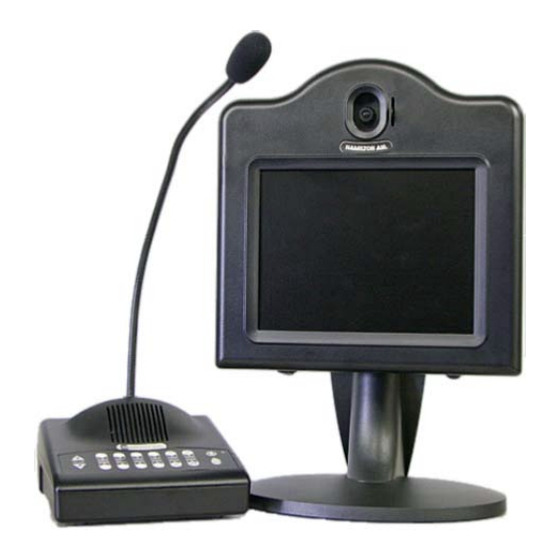
Page 17: 5550 (Current Style) Teller Video Unit Installation
5550 (Current Style) Teller Video Unit Installation The following instructions are for the 5550 which contains both a camera and monitor for two way video. The 5550-1 is the same unit without a camera installed for one way video. Installation Figure 20 Remove the back cover from the stand by pulling out from the top of the cover. - Page 18 Service Adjustments A momentary service/mirror switch on the bottom left side of the Figure 22 video head (see Figure 22) disconnects the external wiring and internally connects the camera to the monitor for testing purposes. The service/mirror switch does not exist on the 5550-1 since no camera is present.
-
Page 19: 5550 (Original Style) Teller Video Unit Installation
5550 (Original Style) Teller Video Unit Installation The following instructions are for the original style 5550 that contains both a camera and monitor for two-way video. The 5550-1 is the same unit without a camera installed for one-way video. Assembly The 5550 is shipped fully assembled except for the base. - Page 20 Figure 25 Connect the supplied 12VDC power supply to the power socket on the back of the stand and plug it into a 110VAC outlet. If a different power supply must be used for some reason, it must be rated for at least 2A. The center conductor of the 2.1mm barrel connector is positive.
-
Page 21: 5517 Remote Video Unit Installation
Optionally Hamilton Air pneumatic units that have an E0873 I/O Control Board can use an E10036 Video Power Control Cable to control the relay board in the video head. See the note below Figure 28. - Page 22 pneumatic unit and then install the end caps from the accessory bag into both ends of the mounting arm. Plug the power supply into a 110VAC outlet. Tilt the camera vertically in its bracket to achieve the desired viewing angle. To view the image, temporarily connect a service monitor to the “camera”...
-
Page 23: E0885 Video Power Control Kit Installation
The switch can be mounted in any suitable location in the teller area. Figure 28 Important Note: Newer Hamilton Air units that have an E0873 I/O Control Board do not require the Video Power Control Kit. For these units use a Video Power Control Cable (E10036) to connect the I/O Board in the pneumatic unit to the Relay Board in the 5517. -
Page 24: 5517 Camera Tilt Kit Installation Instructions
5517 Camera Tilt Kit Installation Instructions The Camera Tilt Kit consists of the parts needed to upgrade an existing 5517 Remote Video Unit for camera tilt capability. This allows tellers to remotely tilt the lane camera using buttons on their audio console. - Page 25 Replace the nylon spacers in the camera mounting holes of the bracket with the new spacers from the kit. Making sure the camera cable exits below the camera, install the camera back into the bracket using the longer screws included in the kit. The screws should be snug but not over tightened to avoid “mushrooming”...
-
Page 26: 5550/5517 Lcd Menu Adjustments
5550/5517 LCD Menu Adjustments Four types of LCD screens have been used to manufacture 5550 and 5517 video units. Refer to the appropriate menu button arrangement below for tips on navigating the menu. This menu board is located below the LCD screen. A dual color LED on the right side of the board indicates power status: green = on &... -
Page 27: E0465-3Wd-Lp License Plate Camera Kit Installation
E0465-3WD-LP License Plate Camera Kit Installation The following instructions are for mounting the License Plate Camera assembly on the back side of a 5517 Video Unit. This camera is used for viewing the rear license plate of a vehicle as it leaves the drive-up lane. -
Page 28: Audio Matrix Switch Settings
Background Noise Cancellation” later in this document. The echo canceller must be set for dynamic learning when using 5501 consoles. MIC DC Switches: These switches only exist on older 5000 Series audio matrixes and are used to determine if the lane microphone is a Dynamic (UP) or Electret Condenser (DOWN) type. Since the electret type is standard (and recommended) this switch must be down or the mic will not work. -
Page 29: Video Matrix Switch Settings
Video Matrix Switch Settings Refer to Figure 34 for the dip switch pack located on the end of the video matrix. Factory settings are shown in bold. Figure 34 Feature Switch # Up (Off) Down (On) Driveway Only All Cameras Idle Console View Normal Static... -
Page 30: Adjusting The Audio System
Adjusting the Audio System The speaker (SPK) and microphone (MIC) pots on the audio matrix (see Figure 2) provide the main volume adjustment for the system. There are a set of pots for each customer lane. The speaker pot adjusts the outgoing volume to the customer lane while the microphone pot adjusts the incoming volume to the teller. -
Page 31: 5501 Series Audio Console Firmware
5501 Series Audio Console Firmware IMPORTANT: The main circuit board used in 5501 series consoles has changed to accommodate newer components beginning with version 2.0. The version number is shown with 2 bold numbers below the bar code on the serial number label on the bottom of the console. The EPROM's used in version 2.# consoles are not compatible with earlier versions of consoles and vice versa - do not try to swap these EPROM's. -
Page 32: Changing The Call Tone Type & Volume
Changing the Call Tone Type & Volume The call tone type and volume are system wide parameters which are stored in the audio matrix. Any audio console in the system can be used to change these parameters as follows. Press the LANE 1 key and the HOLD key at the same time. Lane 1 & 2 indicators light orange. Press the LANE 2 key to rotate through the call tone types until the desired tone is heard. -
Page 33: System Operating Instructions
System Operating Instructions Each lane key on the audio console has an indicator light. Interpret the lights as follows. RED (fast flash)......Customer CALLING for service GREEN (steady)......Customer in 2-WAY CONTACT with your console RED (steady)........Customer in 2-WAY CONTACT with another console GREEN (slow flash)....Customer placed on HOLD from your console RED (slow flash)......Customer placed on HOLD from another console Operate the Teller Console as follows. -
Page 34: Echo Canceller & Background Noise Cancellation
In effect, the teller hears their own voice. The echo cancellation circuitry in 5000 Series consoles is designed to eliminate this issue. The echo canceller can have either dynamic or fixed learning. Dynamic learning adjusts for the best possible cancellation setting while a lane is selected. -
Page 35: 5001-1 Stand Alone Audio System
5001-1 Stand Alone Audio System The model 5001-1 Audio System is a discontinued product that is shown here for service purposes. The replacement is a 5501-1 which is a kit consisting of a 5501-2 Console, a 5003 Matrix and a power supply. -
Page 36: Troubleshooting Tips
Repeat for the 2nd Lane Set the lane 2 pots to the same settings as lane 1 and test. Usually these settings will work for both lanes. If adjustments need to be made, follow the steps above. Adjustment Hint: The 5001-1 Audio System does not like to be too loud. Adjust the volumes to the lowest settings where the level is OK. - Page 37 Audio issues – Isolate audio problems by determining if the problem exists only when using a particular audio console or when communicating with a particular lane. Before deciding that a particular console is bad, try plugging it into a different port of the matrix. Lane connectors can also be swapped at the matrix to see if a problem follows the physical lane or stays with the same lane number on the matrix.
-
Page 38: Frequently Asked Questions
8AM to 5PM Eastern time, excluding holidays. Audio Q. Why is there sometimes a “gurgling” sound in the incoming audio of a 5000 Series audio console? A. This is the left over effect of background noise cancellation when the background noise is constantly changing and the processor cannot keep up with the changes. - Page 39 If a 3000 Series matrix is being used, it is recommended to only use 3000 Series consoles. A 5000 Series console may have issues at times such as a delay when selecting a lane or having to select a lane twice before it works. A 4000 Series console may completely lock up.
- Page 40 A. Generally speaking the answer is yes, but observe the following guidelines: 4000 and 5000 Series audio matrixes can replace each other with no problems even if the system has video. A 4000 Series audio matrix will work fine with a 5000 Series video matrix or vice versa.
- Page 41 Q. What can be done about wind noise at the customer lane? A. An External Universal Microphone Assembly (E0957) is available and has worked well in several locations that were experiencing wind noise problems. It incorporates a combination of foam, scotchbrite and a large screened opening to break up the wind.
- Page 42 Q. Is it possible to use audio and video matrixes from different series together on the same system? A. 4000 and 5000 Series audio and video matrixes can be interchanged. 3000 Series audio matrixes can only be used with 3000 Series video matrixes since the communications and cabling are different.
- Page 43 Q. When a teller selects a particular lane, the teller monitor either doesn’t lock in on that lane camera or it will lock in initially but then start cycling between lanes again. The problem may be intermittent and not all lanes may be affected. What causes this? A.
-
Page 44: Hamilton Audio/Video Part Numbers
Hamilton Audio/Video Part Numbers The number preceding the part number indicates the photo which follows this listing. Audio Consoles 5501-2......2 Lane Audio Console w/Cable 5501-4......4 Lane Audio Console w/Cable 5501-8......8 Lane Audio Console w/Cable 5501-12......12 Lane Audio Console w/Cable 5501-1......Kit, 1 on 2 Audio System (5501-2 w/5003 & Power Supply) Audio Console Parts &... - Page 45 Lane Audio E0680......Audio Cable (sold in 1000’ spools) E0604......Lane Microphone w/48” Cable E0957......Lane Microphone w/Enclosure, Universal B4956......Lane Speaker, 3” E0958-KIT....Cat 5 Lane Speaker Driver Kit w/Power Supply 5570......Remote Customer Audio Console (for standard audio cable) 5571......Cat 5 Remote Customer Audio Console w/Power Supply (for Cat 5 cable) 5572......Remote Customer “In-Wall”...
- Page 46 Power Supplies & Accessories E0736......12VDC / 5.5A Power Supply w/phoenix connector E10171......12VDC / 5.5A Power Supply w/barrel connector E10149......12VDC / 2A Power Supply w/phoenix connector E0884......12VDC / 2A Power Supply w/barrel connector E0947......12VDC / 1A Power Supply w/phoenix connector E0946......12VDC / 1A Power Supply w/barrel connector E10159......Power Adapter, Phoenix to Barrel Connector E10036......Video Power Control Cable (only for use with pneumatic units having E0873 I/O Control Bd.) E0885......Video Power Control Kit, 12VDC / 1A (for 5517 &...
-
Page 47: Part Number Photos
Part Number Photos Audio Consoles (1) 5501-2 (2) 5501-4 (3) 5501-8 (4) 5501-12 (5) 5501-1 (KIT) Audio Console Parts & Accessories (6) 5098KIT (7) E0894 (8) E0605 (9) E0618 (10) 802-420 (11) E0764 (12) B6077 (13) 5501-HWB (14) 5501-VWB (15) B6074-KITB (16) B6074-KITR 08-315 (3/6/12) - Page 48 Matrixes (17) 5003 (18) 5004 (19) 5002-4 (20) 5002-8 (21) 5002-12 (22) 5006 (23) 5005-4 (24) 5005-8 (25) 5005-12 08-315 (3/6/12)
- Page 49 Lane Audio (26) E0680 (27) E0604 (28) E0957 (29) B4956 (30) E0958-KIT (31) 5570 / 5571 (32) 5572 / 5573 Headsets & Handsets (33) CS55 (34) 5015 (35) 5014 (36) E10052 (37) 5512 08-315 (3/6/12)
- Page 50 Video Units (38) 5550 (39) 5550-1 (40) 5517 (41) E0465-3WD (42) E0465-3WD-LP Video Accessories (43) B6724 (44) B6075 (45) H3655 (46) B6712 (47) E10039 08-315 (3/6/12)
- Page 51 Power Supplies & Accessories (48) E0736 (49) E10171 (50) E10149 (51) E0884 (52) E0947 (53) E0946 (54) E10159 (55) E10036 (56) E0885 (57) E0740 (58) E0737 08-315 (3/6/12)
- Page 52 3143 Production Drive Fairfield, OH 45014 Phone: 513-874-3733 www.hamiltonsafe.com For tech support on these products call 877-236-0245 08-315 (3/6/12)
Need help?
Do you have a question about the 5000 Series and is the answer not in the manual?
Questions and answers