
Related Manuals for Supermicro SuperServer SYS-E200-12D-10C


Summary of Contents for Supermicro SuperServer SYS-E200-12D-10C
- Page 1 SuperServer ® SYS-E200-12D-10C SYS-E200-12D-8C SYS-E200-12D-4C USER’S MANUAL Revision 1.0a...
- Page 2 State of California, USA. The State of California, County of Santa Clara shall be the exclusive venue for the resolution of any such disputes. Supermicro's total liability for all claims will not exceed the price paid for the hardware product.
- Page 3 If you have any questions, please contact our support team at: support@supermicro.com This manual may be periodically updated without notice. Please check the Supermicro website for possible updates to the manual revision level. Secure Data Deletion A secure data deletion tool designed to fully erase all data from storage devices can be found on our website: https://www.supermicro.com/about/policies/disclaimer.cfm?url=/wdl/utility/...
-
Page 4: Table Of Contents
Preface Contents Contacting Supermicro ......................6 Chapter 1 Introduction 1.1 Overview ..........................7 1.2 System Features ........................8 Front View ...........................8 Control Panel ........................8 1.3 Motherboard Layout ......................10 Quick Reference Table ......................11 System Block Diagram ......................13 1.4 Server Installation and Setup .....................14 Unpacking the System ......................14 Warnings and Precautions ....................14... - Page 5 Preface 3.5 LED Indicators ........................36 Chapter 4 Software 4.1 Microsoft Windows OS Installation ..................38 4.2 Driver Installation ........................40 4.3 SuperDoctor 5 ........................41 ® 4.4 IPMI ............................42 BMC ADMIN User Password ...................42 Appendix A Standardized Warning Statements for AC Systems Appendix B System Specifications...
-
Page 6: Contacting Supermicro
San Jose, CA 95131 U.S.A. Tel: +1 (408) 503-8000 Fax: +1 (408) 503-8008 Email: marketing@supermicro.com (General Information) Sales-USA@supermicro.com (Sales Inquiries) Government_Sales-USA@supermicro.com (Gov. Sales Inquiries) support@supermicro.com (Technical Support) RMA@supermicro.com (RMA Support) Webmaster@supermicro.com (Webmaster) Website: www.supermicro.com Europe Address: Super Micro Computer B.V. -
Page 7: Chapter 1 Introduction
Mini-1U, (WxHxD) 7.7 x 1.7 x 8.9 in. ( 195 x 43 x 226 mm) Notes: A Quick Reference Guide can be found on the product page of the Supermicro website. The following safety models associated with the SYS-E200-12D-10C/8C/4C have been... -
Page 8: System Features
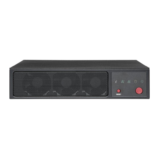
Chapter 1: Introduction 1.2 System Features The following views of the system display the main features. Refer to Appendix B for additional specifications. Front View Control Panel Figure 1-1. Front View Control Panel NIC LEDs HDD LED Information LED Power Fail LED Reset Button Power Button Figure 1-2. - Page 9 Chapter 1: Introduction Information LED Color, Status Description An overheat condition has occurred. (This may be caused by Red, solid cable congestion.) Red, blinking at 1Hz Fan failure, check for an inoperative fan. Red, blinking at 0.25Hz Power failure, check for a non-operational power supply. UID has been activated locally to locate the server in a rack Blue, solid environment.
-
Page 10: Motherboard Layout
Chapter 1: Introduction 1.3 Motherboard Layout Below is a layout of the X12SDV-10C/8C/4C-SPT4F motherboard with jumper, connector and LED locations shown. See the table on the following page for descriptions. For detailed descriptions, pinout information and jumper settings, refer to Chapter 3 or the Motherboard... -
Page 11: Quick Reference Table
Chapter 1: Introduction Quick Reference Table Jumper Description Default Setting JBM1 IPMI Shared LAN Enable/Disable Open (Enabled) JBT1 CMOS Clear Open (Normal) JPG1 VGA Enable/Disable Pins 1-2 (Enabled) JPME2 ME Manufacturing Mode Pins 1-2 (Normal) JPT1 Onboard TPM 2.0 Enable/Disable Pins 1-2 (Enabled) JPTG1 LAN1/2 Enable/Disable... - Page 12 Chapter 1: Introduction Connector Description ATX Power Signal Header (Supermicro P/N for cable: CBL-PWEX-1063) SLOT7 PCIe 4.0 x8 Slot USB0/1 USB 2.0 Header USB2/3 Back Panel USB 3.0 Ports VGA Port Differences between Motherboard Models Motherboard Model Name X12SDV-4C X12SDV-8C...
-
Page 13: System Block Diagram
Chapter 1: Introduction System Block Diagram The block diagram below shows the connections and relationships between the subsystems and major components of the overall system. DDR4 2400/2666/2933 MT/s CH-B CH-A PCIe 4.0 x8 SLOT7 PCIe 4.0 x8 PE1[7:0] PCIe 4.0 x3 PE1[15:13] M.2(M-Key)CONN PCIe 4.0 x1... -
Page 14: Server Installation And Setup
Chapter 1: Introduction 1.4 Server Installation and Setup The server is shipped with the onboard processor and the motherboard installed in the chassis. Several steps are necessary to begin using your server. You must add memory, install the disk drive, and mount the system in place. Unpacking the System Inspect the box in which the system was shipped and note if it was damaged. - Page 15 Chapter 1: Introduction Figure 1-7. Installing Mounting Brackets (Brackets extending out from the chassis) 3. If the system is to be mounted on a sturdy surface such as wall mount, it should be on dry wall and use screws or nails of sufficient strength to support the weight of the system. 4.
-
Page 16: Installing Rack Mounting Brackets
Chapter 1: Introduction Installing Rack Mounting Brackets The chassis can be mounted in a rack using two rack brackets and a two-part power adapter shelf bracket (optional, MCP-290-10110-0B). 1. Attach the rack brackets using three screws through the holes in each bracket to secure the bracket to the chassis. -
Page 17: Chapter 2 Maintenance And Component Installation
Chapter 2: Maintenance and Component Installation Chapter 2 Maintenance and Component Installation This chapter provides instructions on installing and replacing main system components. To prevent compatibility issues, only use components that match the specifications and/or part numbers given. Installation or replacement of most components require that power first be removed from the system. -
Page 18: Accessing The System
Chapter 2: Maintenance and Component Installation 2.2 Accessing the System The CSE-101F features a removable top cover to access to the inside of the chassis. Figure 2-1. Removing the Chassis Cover Removing the Top Cover 1. Power down the system as described in section 2.1. 2. -
Page 19: Memory Support And Installation
Chapter 2: Maintenance and Component Installation 2.3 Memory Support and Installation Note: Check the Supermicro website for recommended memory modules. Important: Exercise extreme care when installing or removing DIMM modules to prevent any possible damage. Memory Support The X12SDV-10C/8C/4C-SPT4F motherboard supports up to 128GB of ECC or non-ECC DDR4 RDIMM/UDIMM memory to 2667 MT/s (10C and 8C) and 2933 MT/s (4C). - Page 20 Chapter 2: Maintenance and Component Installation LED3 JPG1:VGA 1-2:ENABLE 2-3:DISABLE COM1 Intel IPMI_LAN X550 USB 2/3(3.0) Aspeed 2600 LAN1/2 LEDT4 LEDT3 JMD1_SRW1 LEDT2 LEDT1 LAN3/4 JPV1 JMD1:M.2-HC PCIe 4.0 X4/S-SATA 3.0 JMD1 LED1 P1_NVME0 JPF1: 1-2:NORMAL 2-3:POWER FORCE ON JTPM1 FAN2 JGP1 JPF1...
-
Page 21: Installing Memory
Chapter 2: Maintenance and Component Installation Installing Memory When installing memory modules, the DIMM slots should be populated in the following order: DIMMA1, DIMMB1. • Always use DDR4 DIMM modules of the same size, type and speed. Mixing memory modules of different types and speeds is not allowed. •... -
Page 22: Solid State Storage
Chapter 2: Maintenance and Component Installation Solid State Storage This motherboard supports an internally mounted solid state storage card by means of an M.2 slot supporting PCIe. Figure 2-3. Installing an M.2 Expansion Card Installing the M.2 Card 1. Access the motherboard and locate the M.2 connector (Figure 1.5, JMD1: M2) 2. -
Page 23: Motherboard Battery
Chapter 2: Maintenance and Component Installation Motherboard Battery The motherboard uses non-volatile memory to retain system information when system power is removed. This memory is powered by a lithium battery residing on the motherboard. Figure 2-4. Installing the Onboard Battery Replacing the Battery 1. -
Page 24: Chassis Components
Chapter 2: Maintenance and Component Installation 2.4 Chassis Components System Cooling The CSE-101F includes three 4-cm fans. Replacing the System Fan 1. Power down the system as described in section 2.1 and remove the AC power cord and the chassis cover. 2. -
Page 25: Chapter 3 Motherboard Connections
Chapter 3 Motherboard Connections Chapter 3 Motherboard Connections This section describes the connections on the X12SDV-10C/8C/4C-SPT4F motherboard and provides pinout definitions. Note that depending on how the system is configured, not all connections are required. The LEDs on the motherboard are also described here. A motherboard layout indicating component locations may be found in Chapter 1. -
Page 26: Headers And Connectors
Chapter 3 Motherboard Connections 3.2 Headers and Connectors Chassis Intrusion A Chassis Intrusion header is located at JL1 on the motherboard. Attach the appropriate cable from the chassis to inform you of a chassis intrusion when the chassis is opened. Refer to the table below for pin definitions. - Page 27 Chapter 3 Motherboard Connections Fan Headers There are three 4-pin fan headers (FAN–FAN2, FANA) on the motherboard. All these 4-pin fan headers are backwards compatible with the traditional 3-pin fans. However, fan speed control is available for 4-pin fans only by Thermal Management via the Hardware Monitoring in the BIOS.
- Page 28 Chapter 3 Motherboard Connections M.2 Slot This motherboard has one M.2 slot (JMD1). M.2 was formerly known as Next Generation Form Factor (NGFF) and serves to replace mini PCIe. M.2 allows for a variety of card sizes, increased functionality, and spatial efficiency. The M.2 slot at JMD1 supports an M-Key PCIe 4.0 x4/SATA 3.0 SSD cards in the 2280 form factor.
-
Page 29: Control Panel
JF1 contains header pins for various buttons and indicators that are normally located on a control panel at the front of the chassis. These connectors are designed specifically for use with Supermicro chassis. See the figure below for the descriptions of the front control panel buttons and LED indicators. - Page 30 Chapter 3 Motherboard Connections Power Button The Power Button connection is located on pins 1 and 2 of JF1. Momentarily contacting both pins will power on/off the system. This button can also be configured to function as a suspend button with a setting in the BIOS. To turn off the power when the system is in suspend mode, press the button for 4 seconds or longer.
- Page 31 Chapter 3 Motherboard Connections Overheat (OH)/Fan Fail Connect an LED cable to pins 7 and 8 of the Front Control Panel to use the Overheat/Fan Fail LED connections. The LED on pin 8 provides warnings of overheating or fan failure. OH/Fan Fail LED OH/Fan Fail Indicator Pin Definitions (JF1)
-
Page 32: Ports
Chapter 3 Motherboard Connections 3.3 Ports Rear I/O Ports Description Description Dedicated IPMI LAN port RJ45 10GbE LAN port USB 3.0 port SFP28 25GbE LAN port USB 3.0 port SFP28 25GbE LAN port RJ45 10GbE LAN port VGA port LAN Ports Two 10GbE RJ45 LAN ports (LAN1/2) and two SFP 25GbE LAN ports (LAN3/4) are located on the I/O back panel. - Page 33 Note: UID can also be triggered via IPMI on the motherboard. For more information on IPMI, refer to the IPMI User's Guide posted on our website at https://www.supermicro.com/support/ manuals/. UID Switch...
-
Page 34: Jumpers
Chapter 3 Motherboard Connections 3.4 Jumpers Explanation of Jumpers To modify the operation of the motherboard, jumpers are used to choose between optional settings. Jumpers create shorts between two pins to change the function associated with it. Pin 1 is identified with a square solder pad on the printed circuit board. See the motherboard layout page for jumper locations. - Page 35 Chapter 3 Motherboard Connections 10Gb LAN Enable/Disable Use JPTG1 to enable or disable the 10 GbE LAN. The default setting is Enabled. 10Gb LAN Enable/Disable Jumper Settings Jumper Setting Definition Pins 1-2 Enabled (Default) Pins 2-3 Disabled IPMI Shared LAN Feature Set the JBM1 jumper to enable or disable IPMI shared access on LAN1.
-
Page 36: Led Indicators
Chapter 3 Motherboard Connections VGA Enable/Disable JPG1 allows you to enable or disable the onboard VGA port using the onboard graphics controller. The default setting is Enabled. VGA Enable/Disable Jumper Settings Jumper Setting Definition Pins 1-2 Enabled (Default) Pins 2-3 Disabled Watchdog Watchdog (JWD1) is a system monitor that can reboot the system when a software application... - Page 37 Chapter 3 Motherboard Connections Overheat/Power Fail/Fan Fail LED When the light for LED3 is solid red, it means overheating. When the LED is blinking red, it means a power failure or fan failure. Refer to the table below for more information Overheat/Power Fail/Fan Fail LED Indicator LED Color...
-
Page 38: Chapter 4 Software
1. Create a method to access the MS Windows installation ISO file. That might be a USB flash or media drive or the IPMI KVM console. 2. Retrieve the proper RST/RSTe driver. Go to the Supermicro web page for your motherboard and click on "Download the Latest Drivers and Utilities", select the proper driver, and copy it to a USB flash or media drive. - Page 39 Chapter 4: Software 4. During Windows Setup, continue to the dialog where you select the drives on which to install Windows. If the disk you want to use is not listed, click on “Load driver” link at the bottom left corner. Figure 4-2.
-
Page 40: Driver Installation
The Supermicro website contains drivers and utilities for your system at https://www. supermicro.com/wdl/. Some of these must be installed, such as the chipset driver. After accessing the website, go into the CDR_Images (in the parent directory of the above link) and locate the ISO file for your motherboard. Download this file to a USB flash or media drive. -
Page 41: Superdoctor ® 5
4.3 SuperDoctor ® The Supermicro SuperDoctor 5 is a program that functions in a command-line or web-based interface for Windows and Linux operating systems. The program monitors such system health information as CPU temperature, system voltages, system power consumption, fan speed, and provides alerts via email or Simple Network Management Protocol (SNMP). -
Page 42: Ipmi
This can be found on a sticker on the chassis and a sticker on the motherboard. The sticker also displays the BMC MAC address. If necessary, the password can be reset using the Supermicro IPMICFG tool. Figure 4-5. BMC Password Label The sticker can be found on the pull-out service tag at the front of the chassis. -
Page 43: Appendix A Standardized Warning Statements For Ac Systems
Supermicro's Technical Support department for assistance. Only certified technicians should attempt to install or configure components. Read this appendix in its entirety before installing or configuring components in the Supermicro chassis. These warnings may also be found on our website at http://www.supermicro.com/about/... - Page 44 Appendix A: Warning Statements Warnung WICHTIGE SICHERHEITSHINWEISE Dieses Warnsymbol bedeutet Gefahr. Sie befinden sich in einer Situation, die zu Verletzungen führen kann. Machen Sie sich vor der Arbeit mit Geräten mit den Gefahren elektrischer Schaltungen und den üblichen Verfahren zur Vorbeugung vor Unfällen vertraut. Suchen Sie mit der am Ende jeder Warnung angegebenen Anweisungsnummer nach der jeweiligen Übersetzung in den übersetzten Sicherheitshinweisen, die zusammen mit diesem Gerät ausgeliefert wurden.
- Page 45 Appendix A: Warning Statements . ٌ ا ك ً ف حالة و ٌ يك أى تتسبب ف اصابة جسذ ة ٌ هذا الزهز ع ٌ خطز !تحذ ز قبل أى تعول عىل أي هعذات،يك عىل علن بالوخاطز ال ا ٌجوة عي الذوائز ٍ...
- Page 46 Appendix A: Warning Statements Warnung Vor dem Anschließen des Systems an die Stromquelle die Installationsanweisungen lesen. ¡Advertencia! Lea las instrucciones de instalación antes de conectar el sistema a la red de alimentación. Attention Avant de brancher le système sur la source d'alimentation, consulter les directives d'installation. .יש...
- Page 47 Appendix A: Warning Statements Warnung Dieses Produkt ist darauf angewiesen, dass im Gebäude ein Kurzschluss- bzw. Überstromschutz installiert ist. Stellen Sie sicher, dass der Nennwert der Schutzvorrichtung nicht mehr als: 250 V, 20 A beträgt. ¡Advertencia! Este equipo utiliza el sistema de protección contra cortocircuitos (o sobrecorrientes) del edificio.
- Page 48 Appendix A: Warning Statements Power Disconnection Warning Warning! The system must be disconnected from all sources of power and the power cord removed from the power supply module(s) before accessing the chassis interior to install or remove system components (except for hot-swap components). 電源切断の警告...
- Page 49 Appendix A: Warning Statements אזהרה מפני ניתוק חשמלי !אזהרה יש לנתק את המערכת מכל מקורות החשמל ויש להסיר את כבל החשמלי מהספק .לפני גישה לחלק הפנימי של המארז לצורך התקנת או הסרת רכיבים يجب فصم اننظاو من جميع مصادر انطاقت وإ ز انت سهك انكهرباء من وحدة امداد انطاقت...
- Page 50 Appendix A: Warning Statements Attention Seul le personnel autorisé et le personnel de maintenance qualifié doivent être autorisés à installer, remplacer ou entretenir cet équipement.. !אזהרה .יש לאפשר רק צוות מורשה ואנשי שירות מוסמכים להתקין, להחליף או לטפל בציוד זה .ينبغي...
- Page 51 Appendix A: Warning Statements Warnung Diese Einheit ist zur Installation in Bereichen mit beschränktem Zutritt vorgesehen. Der Zutritt zu derartigen Bereichen ist nur mit einem Spezialwerkzeug, Schloss und Schlüssel oder einer sonstigen Sicherheitsvorkehrung möglich. ¡Advertencia! Esta unidad ha sido diseñada para instalación en áreas de acceso restringido. Sólo puede obtenerse acceso a una de estas áreas mediante la utilización de una herramienta especial, cerradura con llave u otro medio de seguridad.
- Page 52 Appendix A: Warning Statements Battery Handling Warning! There is the danger of explosion if the battery is replaced incorrectly. Replace the battery only with the same or equivalent type recommended by the manufacturer. Dispose of used batteries according to the manufacturer's instructions 電池の取り扱い...
- Page 53 Appendix A: Warning Statements هناك خطر من انفجار يف حالة اسحبذال البطارية بطريقة غري صحيحة فعليل اسحبذال البطارية فقط بنفس النىع أو ما يعادلها مام أوصث به الرشمة املصنعة جخلص من البطاريات املسحعملة وفقا لحعليامت الرشمة الصانعة 경고! 배터리가 올바르게 교체되지 않으면 폭발의 위험이 있습니다. 기존 배터리와 동일하거나 제 조사에서...
- Page 54 Appendix A: Warning Statements ¡Advertencia! Puede que esta unidad tenga más de una conexión para fuentes de alimentación. Para cortar por completo el suministro de energía, deben desconectarse todas las conexiones. Attention Cette unité peut avoir plus d'une connexion d'alimentation. Pour supprimer toute tension et tout courant électrique de l'unité, toutes les connexions d'alimentation doivent être débranchées.
- Page 55 Appendix A: Warning Statements Backplane Voltage Warning! Hazardous voltage or energy is present on the backplane when the system is operating. Use caution when servicing. バックプレーンの電圧 システムの稼働中は危険な電圧または電力が、 バックプレーン上にかかっています。 修理する際には注意く ださい。 警告 当系统正在进行时,背板上有很危险的电压或能量,进行维修时务必小心。 警告 當系統正在進行時,背板上有危險的電壓或能量,進行維修時務必小心。 Warnung Wenn das System in Betrieb ist, treten auf der Rückwandplatine gefährliche Spannungen oder Energien auf.
- Page 56 Appendix A: Warning Statements هناك خطز مه التيار الكهزبايئ أوالطاقة املىجىدة عىل اللىحة عندما يكىن النظام يعمل كه حذ ر ا عند خدمة هذا الجهاس 경고! 시스템이 동작 중일 때 후면판 (Backplane)에는 위험한 전압이나 에너지가 발생 합니다. 서비스 작업 시 주의하십시오. Waarschuwing Een gevaarlijke spanning of energie is aanwezig op de backplane wanneer het systeem in gebruik is.
- Page 57 Appendix A: Warning Statements תיאום חוקי החשמל הארצי !אזהרה .התקנת הציוד חייבת להיות תואמת לחוקי החשמל המקומיים והארציים تركيب املعدات الكهربائية يجب أن ميتثل للقىاويه املحلية والىطىية املتعلقة بالكهرباء 경고! 현 지역 및 국가의 전기 규정에 따라 장비를 설치해야 합니다. Waarschuwing Bij installatie van de apparatuur moet worden voldaan aan de lokale en nationale elektriciteitsvoorschriften.
- Page 58 Appendix A: Warning Statements Attention La mise au rebut ou le recyclage de ce produit sont généralement soumis à des lois et/ou directives de respect de l'environnement. Renseignez-vous auprès de l'organisme compétent. סילוק המוצר !אזהרה .סילוק סופי של מוצר זה חייב להיות בהתאם להנחיות וחוקי המדינה التخلص...
- Page 59 Appendix A: Warning Statements Warnung Gefährlich Bewegende Teile. Von den bewegenden Lüfterblätter fern halten. Die Lüfter drehen sich u. U. noch, wenn die Lüfterbaugruppe aus dem Chassis genommen wird. Halten Sie Finger, Schraubendreher und andere Gegenstände von den Öffnungen des Lüftergehäuses entfernt.
- Page 60 Verbindungskabeln, Stromkabeln und/oder Adapater, die Ihre örtlichen Sicherheitsstandards einhalten. Der Gebrauch von anderen Kabeln und Adapter können Fehlfunktionen oder Feuer verursachen. Die Richtlinien untersagen das Nutzen von UL oder CAS zertifizierten Kabeln (mit UL/CSA gekennzeichnet), an Geräten oder Produkten die nicht mit Supermicro gekennzeichnet sind.
- Page 61 .قيرح وأ لطع يف ببستي دق ىرخأ تالوحمو تالباك يأ مادختسا .ميلسلا سباقلاو لصوملا مجح لبق نم ةدمتعملا تالباكلا مادختسا تادعملاو ةيئابرهكلا ةزهجألل ةمالسلا نوناق رظحيUL وأCSA ( ةمالع لمحت يتلاوUL/CSA) لبق نم ةددحملاو ةينعملا تاجتنملا ريغ ىرخأ تادعم يأ عمSupermicro.
- Page 62 사항을 준수하여 제공되거나 지정된 연결 혹은 구매 케이블, 전원 케이블 및 AC 어댑터를 사용하십시오. 다른 케이블이나 어댑터를 사용하면 오작동이나 화재가 발생할 수 있습니다. 전기 용품 안전법은 UL 또는 CSA 인증 케이블 (코드에 UL / CSA가 표시된 케이블)을 Supermicro 가 지정한 제품 이외의 전기 장치에 사용하는 것을 금지합니다. Stroomkabel en AC-Adapter...
-
Page 63: Appendix B System Specifications
Appendix B: System Specifications Appendix B System Specifications Processors SYS-E200-12D-10C: Single Intel Xeon® Processor D-1749NT SYS-E200-12D-8C: Single Intel Xeon® Processor D-1736NT SYS-E200-12D-4C: Single Intel Xeon® Processor D-1718T Note: Refer to the motherboard specifications pages on our website for updates to supported processors. Chipset Intel®... - Page 64 Appendix B: System Specifications Regulatory Compliance FCC, ICES, CE, VCCI, RCM, UKCA, NRTL, CB Applied Directives, Standards EMC/EMI: 2014/30/EU (EMC Directive) Electromagnetic Compatibility Regulations 2016 FCC Part 15 Subpart B ICES-003 VCCI-CISPR 32 AS/NZS CISPR 32 EN/BS EN55032 EN/BS EN55035 CISPR 32 CISPR 35 EN/BS 61000-3-2...
Need help?
Do you have a question about the SuperServer SYS-E200-12D-10C and is the answer not in the manual?
Questions and answers