Advertisement
Quick Links
Advertisement

Subscribe to Our Youtube Channel
Related Manuals for Supermicro SuperServer SYS-E403-13E-FRN2T


Summary of Contents for Supermicro SuperServer SYS-E403-13E-FRN2T
- Page 1 SuperServer ® SYS-E403-13E-FRN2T USER’S MANUAL Revision 1.0...
- Page 2 State of California, USA. The State of California, County of Santa Clara shall be the exclusive venue for the resolution of any such disputes. Supermicro's total liability for all claims will not exceed the price paid for the hardware product.
- Page 3 If you have any questions, please contact our support team at: support@supermicro.com This manual may be periodically updated without notice. Please check the Supermicro website for possible updates to the manual revision level. Secure Data Deletion A secure data deletion tool designed to fully erase all data from storage devices can be found at our website: https://www.supermicro.com/about/policies/disclaimer.cfm?url=/wdl/utility/...
- Page 4 Preface Contents Contacting Supermicro ......................7 Chapter 1 Introduction 1.1 Overview ..........................8 1.2 System Features ........................9 Front View ...........................9 Control Panel .........................10 Rear View ..........................11 1.4 Motherboard Layout ......................12 Quick Reference Table ......................13 1.5 Server Installation and Setup .....................16 Unpacking the System ......................16 Warnings and Precautions ....................16...
- Page 5 Preface M.2 SSD Installation ......................36 Motherboard Battery ......................37 2.6 Chassis Components ......................38 Installing Storage Drives ....................38 Expansion Cards .......................41 System Cooling .........................43 Mounting on a Surface ......................46 Power Supply ........................49 Power Supply Failure ....................49 Chapter 3 Motherboard Connections 3.1 Power Connections ......................50 3.2 Headers and Connectors ....................51 3.3 Ports ...........................55 I/O Ports ..........................55...
- Page 6 6.5 Frequently Asked Questions ....................75 6.6 Returning Merchandise for Service ..................76 6.7 Battery Removal and Installation ..................76 Battery Removal ........................76 Proper Battery Disposal ....................77 Battery Installation ......................77 6.8 Contacting Supermicro .......................78 Appendix A Standardized Warning Statements for AC Systems Appendix B System Specifications...
- Page 7 San Jose, CA 95131 U.S.A. Tel: +1 (408) 503-8000 Fax: +1 (408) 503-8008 Email: marketing@supermicro.com (General Information) Sales-USA@supermicro.com (Sales Inquiries) Government_Sales-USA@supermicro.com (Gov. Sales Inquiries) support@supermicro.com (Technical Support) RMA@supermicro.com (RMA Support) Webmaster@supermicro.com (Webmaster) Website: www.supermicro.com Europe Address: Super Micro Computer B.V.
- Page 8 4.62" x 10.5" x 16" (117.35 x 266.7 x 406.4 mm) (H x W x D) Note: A Quick Reference Guide can be found on the product page of the Supermicro website. The following safety models associated with the SYS-E403-13E-FRN2T have been certified...
- Page 9 Chapter 1: Introduction 1.2 System Features The following views of the system display the main features. Refer to Appendix B for additional specifications. Front View Power Supply Drive Bays USB 3.2 Ports Expansion Slots COM Port VGA Port Control Panel USB 2.0 Ports 10 GbE LAN Ports Dedicated IPMI LAN Port...
- Page 10 Chapter 1: Introduction Control Panel There are two buttons and several LEDs on the control panel to keep you constantly informed of the overall status of the system as well as the activity and health of specific components. There are also status lights for the power supply. Power Button Reset Button Power LED...
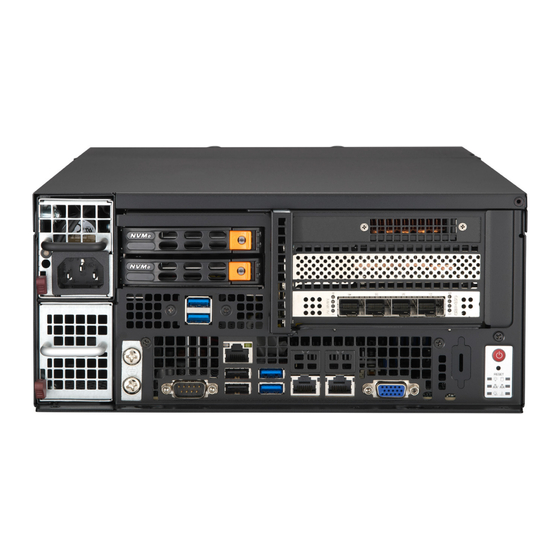
- Page 11 Chapter 1: Introduction Rear View Fans Figure 1-3. System: Rear View System Features: Rear Feature Description Fans Three 8-cm hot-swap fans with dust filters...
- Page 12 Chapter 1: Introduction 1.4 Motherboard Layout Below is a layout of the X13SEW-TF motherboard with jumper, connector, and LED locations shown. See the table on the following page for descriptions. For detailed descriptions, pinout information, and jumper settings, refer to Chapter 3. USB3/4 (3.2 Gen 1) JBR1 IPMI_LAN...
- Page 13 Chapter 1: Introduction Quick Reference Table Jumper Description Default Setting JBR1 BIOS Recovery Pins 1–2 (Normal) JBT1 CMOS Clear Open (Normal) JPL1 I210 LAN1 Enable/Disable Pins 1–2 (Enabled) JPL2 I210 LAN2 Enable/Disable Pins 1–2 (Enabled) JPL3 X550 LAN1 and LAN2 Enable/Disable Pins 1–2 (Enabled) JPME1 ME Recovery...
- Page 14 Description SATA8, SATA9 SATA 3.0 Ports with SuperDOM Power SXB1A, SXB1B, SXB1C PCIe 5.0 x16 + x16 Supermicro Proprietary WIO Left Add-on Card Slots SXB2 PCIe 5.0 x8 (In x16) Supermicro Proprietary WIO Right Add-on Card Slot SGPIO2 Serial Link General Purpose I/O Header USB0/1 Back Panel USB 2.0 Ports...
- Page 15 Chapter 1: Introduction VR14 8 PHASE CPU1 DDR5 DDR5 PECI:30 4800 SOCKET ID:0 #PE0 #PE1/#PE2 DMI3 #PE4 #PE4 #PE3 #PE3 SXB2 (WIO-R) PCIe GEN5 x8 PCIe x8 G5 PE0[15:8] NVME2/3 PCIe GEN5 x8 NVME8/9 MCIO PCIe GEN5 x8 MCIO NVME0/1 PCIe GEN5 x8 SXB1 (WIO-L) MCIO...
- Page 16 Chapter 1: Introduction 1.5 Server Installation and Setup The server is shipped with the onboard processor and the motherboard installed in the chassis. Several steps are necessary to begin using your server. You must add memory, install the storage drives, and mount the system in place. Unpacking the System Inspect the box in which the system was shipped and note if it was damaged.
- Page 17 Chapter 2: Maintenance and Component Installation Chapter 2 Maintenance and Component Installation Note: Maintenance and component installation must be carried out by Supermicro service personnel only. Please ensure that the device is connected to a socket/outlet that has a ground/earth connection.
- Page 18 Chapter 2: Maintenance and Component Installation 2.2 Accessing the System The CSE-E403BiF-000NDBP2 features a lockable and segmented top cover. Open the fan cover to access the fans and fan filters. Remove the system cover to access other system components. Remove the drive cage, the expansion card module, and the air shroud to access the motherboard.
- Page 19 Chapter 2: Maintenance and Component Installation Accessing the Main System 1. Power down the system as described in Section 2.1. 2. Remove one screw on top of the system cover near the I/O panel. See Figure 2-2. 3. Remove two screws on the fan cover if necessary. 4.
- Page 20 Chapter 2: Maintenance and Component Installation Figure 2-3. Slide Cover Off Chassis Caution: Except for short periods of time, do not operate the server without the cover in place. The chassis cover must be in place to allow proper airflow and prevent overheating.
- Page 21 Chapter 2: Maintenance and Component Installation Enabling the Top Cover Lock Function The chassis includes a lock plate that allows the top cover to be locked. 1. Pull the lock plate into a vertical position. 2. Close the fan cover. Make sure the lock plate fits through the slot on the cover. 3.
- Page 22 Chapter 2: Maintenance and Component Installation 2.3 Motherboard Components ESD Precautions Electrostatic Discharge (ESD) can damage electronic com ponents including memory modules. To avoid damaging your DIMM modules, it is important to handle it very carefully. The following measures are generally sufficient to protect your equipment from ESD. •...
- Page 23 Thermal grease is pre-applied on a new heatsink. No additional thermal grease is needed. • Refer to the Supermicro website for updates on processor support. • All graphics in this manual are for illustration purposes only. Your components may look different.
- Page 24 Chapter 2: Maintenance and Component Installation Overview of the Processor Carrier Assembly The processor carrier assembly contains the Intel Xeon processor and a processor carrier. 1. Intel Xeon Processor 2. Processor Carrier Overview of the CPU Socket The CPU socket is protected by a plastic protective cover. 1.
- Page 25 Chapter 2: Maintenance and Component Installation Overview of the Processor Heatsink Module The Processor Heatsink Module (PHM) contains a heatsink, a processor carrier, and the Intel Xeon processor. 1. Heatsink with Thermal Grease 2. Processor Carrier 3. Intel Xeon Processor Processor Heatsink Module (PHM) Bottom View...
- Page 26 Chapter 2: Maintenance and Component Installation Creating the Processor Carrier Assembly To install a processor into the processor carrier, follow the steps below: 1. Before installation, make sure the lever on the processor carrier is pressed down as shown below. 2.
- Page 27 Chapter 2: Maintenance and Component Installation Assembling the Processor Processor Carrier Assembly Heatsink Module (Upside Down) After creating the processor carrier Triangle on the CPU assembly for the processor, mount it onto the heatsink to create the processor heatsink module (PHM): 1.
- Page 28 Chapter 2: Maintenance and Component Installation Preparing the CPU Socket for Installation This motherboard comes with a plastic protective cover installed on the CPU socket. Remove it from the socket to install the Processor Heatsink Module (PHM). Gently pull up one corner of the plastic protective cover to remove it.
- Page 29 Chapter 2: Maintenance and Component Installation Installing the Processor Heatsink Module After assembling the Processor Heatsink Module (PHM), install it onto the CPU socket: 1. Align pin 1 of the PHM with the printed triangle on the CPU socket. See the left image below. 2.
- Page 30 Chapter 2: Maintenance and Component Installation Removing the Processor Heatsink Module Before removing the processor heatsink module (PHM) from the motherboard, shut down the system and then unplug the AC power cord from all power supplies. Then follow the steps below: 1.
- Page 31 Chapter 2: Maintenance and Component Installation 2.5 Memory Support and Installation Note: Check the Supermicro website for recommended memory modules. Important: Exercise extreme care when installing or removing DIMM modules to prevent any possible damage. Memory Support The X13SEW-TF motherboard supports up to 2 TB of ECC RDIMM/RDIMM 3DS DDR5 memory in eight memory slots.
- Page 32 Chapter 2: Maintenance and Component Installation DDR5 Memory Support for the 4th Generation Intel Xeon Scalable Processors-SP ® ® Speed (MT/s) DIMM Capacity (GB) One DIMM per Two DIMMs Ranks Per Channel per Channel Type DIMM and Data Width (Stack) Memory Memory Density...
- Page 33 Chapter 2: Maintenance and Component Installation DDR5 Memory Support for the 5th Generation Intel Xeon Scalable Processors-SP ® ® Speed (MT/s) DIMM Capacity (GB) One DIMM per Two DIMMs Ranks Per Channel per Channel Type DIMM and Data Width (Stack) Memory Memory Density...
- Page 34 Chapter 2: Maintenance and Component Installation General Guidelines for Optimizing Memory Performance • It is recommended to use DDR5 memory of the same type, size, and speed. • Mixed DIMM speeds can be installed, however, all will run at the speed of the slowest DIMM. •...
- Page 35 Chapter 2: Maintenance and Component Installation DIMM Installation JUIDB1 COM1 1. Insert DIMM modules in the following order: USB3/4 (3.2 Gen 1) LAN2 LAN1 IPMI_LAN USB0/1 DIMMA1, DIMMB1, DIMMC1, DIMMD1, JNCSI1 JPFR2 JTPM X550 DIMME1, DIMMF1, DIMMG1, DIMMH1, and MH17 M.2 NVME JBT1 insert the desired number of DIMMs into the...
- Page 36 Chapter 2: Maintenance and Component Installation M.2 SSD Installation The X13SEW-TF supports three M.2 SSD connectors. To install an M.2 SSD, first locate the connector and the standoff on the motherboard. 1. Remove the screw from the standoff and set aside. 2.
- Page 37 Chapter 2: Maintenance and Component Installation Motherboard Battery This section describes how to remove and install the motherboard battery. Figure 2-7. Installing the Onboard Battery Replacing the Battery 1. Remove power from the system as described in Section 2.1. 2. Push aside the small clamp that covers the edge of the battery. When the battery is released, lift it out of the holder.
- Page 38 Up to four fixed 2.5" internal drives that are installed in a removable drive cage and then inserted into the chassis (drive cage p/n MCP-220-40301-0N). Note: Enterprise level storage drives are recommended for use in Supermicro servers. For compatible storage drives, see the system web page.
- Page 39 Chapter 2: Maintenance and Component Installation 5. Pull the drive cage up using the provided plastic handles. 6. Place the drives inside the drive cage, stacked up to two units on each end, then secure them inside the drive bays with the included screws. 7.
- Page 40 Chapter 2: Maintenance and Component Installation Installing External Drives These drives are hot-swap, so power does not need to be removed prior to installing. The drive carriers help promote proper airflow so should remain in the system regardless of if a drive is installed or not.
- Page 41 Chapter 2: Maintenance and Component Installation Expansion Cards The SYS-E403-13E-FRN2T supports up to three PCI-E slots on the riser card. Follow the table printed on the riser card to set the JSEL jumper. The IIO configurations may also need to be set in the BIOS. Installing Expansion Cards 1.
- Page 42 Chapter 2: Maintenance and Component Installation Expansion Card Module Ex pa ns ion Ca rd (optional) Figure 2-14. Expansion Card Module Removed 6. Install the I/O shields for the expansion slots that are being populated. 7. Connect the power cable to the expansion card if necessary. 8.
- Page 43 Chapter 2: Maintenance and Component Installation System Cooling The CSE-E403BiF-000NDBP2 includes three hot-swap 8-cm fans. Installing or Replacing the System Fan 1. Access the fans as described in Section 2.2. 2. Press the latch at the side of the fan. See the figure below. 3.
- Page 44 Chapter 2: Maintenance and Component Installation Installing or Replacing the Fan Filters The system supports three fan filters that can be removed and cleaned. Power to the system can remain on while the the fan filters are removed or installed. 1.
- Page 45 Chapter 2: Maintenance and Component Installation Installing the Air Shroud The air shroud directs airflow from two of the fans to the center of the motherboard. 1. If you are installing expansion cards that require power from the power supply, you must cut a hole to route the power cable from the power supply to the expansion module.
- Page 46 Chapter 2: Maintenance and Component Installation Mounting on a Surface The CSE-E403BiF-000NDBP2 can be mounted directly on a surface using the mounting brackets and mounting screws or nails. The following procedure describes how to mount the system to a sturdy surface. Use screws or nails of sufficient strength to support the weight of the system.
- Page 47 Chapter 2: Maintenance and Component Installation 2. Decide on an orientation to mount the server. The server can only be mounted with the I/O panel facing left or right. 76.20mm 420mm I/O Facing Left 76.20mm 420mm I/O Facing Right Figure 2-19. Possible Mounting Orientations...
- Page 48 Chapter 2: Maintenance and Component Installation 3. Mark two keyhole spots on the surface where the server will be mounted. The two keyholes for each orientation are circled in red. See Figure 2-16. 4. Install the two keyhole screws or nails. 5.
- Page 49 If the power supply fails, it will be necessary to shut down the system in order to install a new one of the same model (p/n PWS-804P-1R). New units can be ordered directly from Supermicro or authorized distributors. Replacing the Power Supply 1.
- Page 50 Chapter 3: Motherboard Connections Chapter 3 Motherboard Connections This section describes the connections on the motherboard and provides pinout definitions. Note that depending on how the system is configured, not all connections are required. The LEDs on the motherboard are also described here. A motherboard layout indicating component locations may be found in Chapter 1.
- Page 51 Chapter 3: Motherboard Connections 3.2 Headers and Connectors Chassis Intrusion A Chassis Intrusion header is located at JL1 on the motherboard. Attach the appropriate cable from the chassis to inform you of a chassis intrusion when the chassis is opened. Refer to the table below for pin definitions.
- Page 52 Chapter 3: Motherboard Connections Fan Headers There are six 4-pin fan headers (FAN1 FAN6) on the motherboard. All these 4-pin fan headers – are backwards compatible with the traditional 3-pin fans. However, fan speed control is available for 4-pin fans only by Thermal Management via the IPMI 2.0 interface. Refer to the table below for pin definitions.
- Page 53 Baseboard Management Controller (BMC) and a Network Interface Controller (NIC). For the network sideband interface to work properly, you will need to use a NIC add-on card that supports NC-SI and must use a special cable. Contact Supermicro at www.supermicro.com to purchase the cable for this header.
- Page 54 In addition, this motherboard has two SATA 3.0 ports (SATA8, SATA9) that can be used with Supermicro's SuperDOM SATA DOM connectors with power pins built in, and do not require external power cables. Supermicro SuperDOMs are backward compatible with regular SATA HDDs or SATA DOMs that need external power cables.
- Page 55 Chapter 3: Motherboard Connections 3.3 Ports I/O Ports See Figure 3-1 below for the locations and descriptions of the various I/O ports on the front of the system. Figure 3-1. I/O Ports Rear I/O Ports Description Description Description COM1 USB3 (3.2 Gen 1) IPMI_LAN USB4 (3.2 Gen 1) UID Switch...
- Page 56 Chapter 3: Motherboard Connections VGA Port A video (VGA) port is located on the I/O back panel. Refer to the board layout below for the location. Universal Serial Bus (USB) Ports There are two USB 2.0 ports (USB0/1) and two USB 3.2 Gen 1 ports (USB3/4) on the I/O back panel.
- Page 57 JF1 contains header pins for various buttons and indicators that are normally located on a control panel at the front of the chassis. These connectors are designed specifically for use with Supermicro chassis. See the figure below for the descriptions of the front control panel buttons and LED indicators.
- Page 58 Chapter 3: Motherboard Connections Power Button The Power Button connection is located on pins 1 and 2 of JF1. Momentarily contacting both pins will power on/off the system. This button can also be configured to function as a suspend button (with a setting in the BIOS – see Chapter 4). To turn off the power when the system is in suspend mode, press the button for 4 seconds or longer.
- Page 59 Chapter 3: Motherboard Connections HDD LED The HDD LED connection is located on pins 13 and 14 of JF1. Attach a cable to pin 14 to show storage drive activity status. Refer to the table below for pin definitions. HDD LED Pin Definitions (JF1) Pins Definition...
- Page 60 Chapter 3: Motherboard Connections 3.4 Jumpers Explanation of Jumpers To modify the operation of the motherboard, jumpers are used to choose between optional settings. Jumpers create shorts between two pins to change the function associated with it. Pin 1 is identified with a square solder pad on the printed circuit board. See the motherboard layout page for jumper locations.
- Page 61 Chapter 3: Motherboard Connections BIOS Recovery Close pins 2-3 of jumper JBR1 for BIOS recovery. The default setting is on pins 1 and 2 for normal operation. Refer to the table below for jumper settings. The default setting is Normal. BIOS Recovery Jumper Settings Jumper Setting...
- Page 62 Chapter 3: Motherboard Connections 3.5 LED Indicators BMC LAN LEDs A BMC LAN is located on the I/O back panel. The amber LED on the right indicates activity, while the green LED on the left indicates the speed of the connection. Refer to the table below for more information.
- Page 63 Chapter 3: Motherboard Connections Onboard Power LED LEDPWR is the onboard Power LED. When this LED is on, the system is on. Turn off the system and unplug the power cord before removing or installing components. Refer to the table below for more information. Onboard Power LED Indicator LED Color Definition...
- Page 64 1. Create a method to access the Microsoft Windows installation ISO file. That can be a USB flash or media drive. 2. Go to the Supermicro web page for your motherboard and click on "Download the Latest Drivers and Utilities", select the proper driver, and copy it to a USB flash drive.
- Page 65 Chapter 4: Software 4. During Windows Setup, continue to the dialog where you select the drives on which to install Windows. If the disk you want to use is not listed, click on “Load driver” link at the bottom left corner. Figure 4-2.
- Page 66 The Supermicro website contains drivers and utilities for your system at https://www. supermicro.com/wdl/driver. Some of these must be installed, such as the chipset driver. After accessing the website, go into the CDR_Images (in the parent directory of the above link) and locate the ISO file for your motherboard. Download this file to a USB flash drive or media drive.
- Page 67 4.3 SuperDoctor ® The Supermicro SuperDoctor 5 is a program that functions in a command-line or web-based interface for Windows and Linux operating systems. The program monitors such system health information as CPU temperature, system voltages, system power consumption, fan speed, and provides alerts via email or Simple Network Management Protocol (SNMP).
- Page 68 Chapter 6: Optional Components Chapter 5 Optional Components This chapter describes alternate configurations and optional system components. Optional Parts List Description Part Number Internal U.2 drive cable CBL-MCIO-1245U2Y-E Nvdia GPU rear-support bracket MCP-120-82906-0N 5.1 Internal U.2 Drive Cable This cable must be used if adding an optional internal U.2 drive to the system. Details: MCIO x8 to 2x SFF-8639/U.2+power, 45-cm, G5, RoHS 5.2 Nvidia GPU Rear-support Bracket This cable must be used if adding an optional GPU to the system.
- Page 69 Chapter 6 Troubleshooting and Support 6.1 Information Resources Website A great deal of information is available on the Supermicro website, www.supermicro.com. Figure 7-1. Supermicro Website • Specifications for servers and other hardware are available by clicking the menu icon, then selecting the Products option.
- Page 70 Security Center for recent security notices Supermicro Phone and Addresses 6.2 Baseboard Management Controller (BMC) The system supports the Baseboard Management Controller (BMC). BMC is used to provide remote access, monitoring, and management. There are several BIOS settings that are related to BMC.
- Page 71 Chapter 6: Troubleshooting and Support 6.3 Troubleshooting Procedures Use the following procedures to troubleshoot your system. If you have followed all of the procedures below and still need assistance, refer to the ‘Technical Support Procedures’ and/ or ‘Returning Merchandise for Service’ section(s) in this chapter. Always disconnect the AC power cord before adding, changing or installing any non hot-swap hardware components.
- Page 72 Chapter 6: Troubleshooting and Support back into the system to retest. Add one component at a time to isolate which one may have caused the system boot issue. Memory Errors When suspecting faulty memory is causing the system issue, check the following: 1.
- Page 73 Chapter 6: Troubleshooting and Support Note: Click on the "Tested Memory List" link on the motherboard's product page to see a list of supported memory. 3. Drive support: Make sure that all storage drives work properly. Replace any bad drives with good ones.
- Page 74 Chapter 6: Troubleshooting and Support 6.4 Technical Support Procedures Before contacting Technical Support, please take the following steps. Also, note that as a motherboard manufacturer, we do not sell directly to end-users, so it is best to first check with your distributor or reseller for troubleshooting services. They should know of any possible problem(s) with the specific system configuration that was sold to you.
- Page 75 Updated BIOS files are located on our website at http://www. supermicro.com/ResourceApps/BIOS_IPMI_Intel.html. Check our BIOS warning message and the information on how to update your BIOS on our website. Select your motherboard model and download the BIOS file to your computer. Also, check the current BIOS revision to make sure that it is newer than your BIOS before downloading.
- Page 76 Shipping and handling charges will be applied for all orders that must be mailed when service is complete. For faster service, RMA authorizations may be requested online (http://www.supermicro.com/ support/rma/). This warranty only covers normal consumer use and does not cover damages incurred in shipping or from failure due to the alteration, misuse, abuse or improper maintenance of products.
- Page 77 Chapter 6: Troubleshooting and Support Proper Battery Disposal Please handle used batteries carefully. Do not damage the battery in any way; a damaged battery may release hazardous materials into the environment. Do not discard a used battery in the garbage or a public landfill. Please comply with the regulations set up by your local hazardous waste management agency to dispose of your used battery properly.
- Page 78 San Jose, CA 95131 U.S.A. Tel: +1 (408) 503-8000 Fax: +1 (408) 503-8008 Email: marketing@supermicro.com (General Information) Sales-USA@supermicro.com (Sales Inquiries) Government_Sales-USA@supermicro.com (Gov. Sales Inquiries) support@supermicro.com (Technical Support) RMA@supermicro.com (RMA Support) Webmaster@supermicro.com (Webmaster) Website: www.supermicro.com Europe Address: Super Micro Computer B.V.
- Page 79 Supermicro's Technical Support department for assistance. Only certified technicians should attempt to install or configure components. Read this appendix in its entirety before installing or configuring components in the Supermicro chassis. These warnings may also be found on our website at http://www.supermicro.com/about/...
- Page 80 Appendix A: Warning Statements Warnung WICHTIGE SICHERHEITSHINWEISE Dieses Warnsymbol bedeutet Gefahr. Sie befinden sich in einer Situation, die zu Verletzungen führen kann. Machen Sie sich vor der Arbeit mit Geräten mit den Gefahren elektrischer Schaltungen und den üblichen Verfahren zur Vorbeugung vor Unfällen vertraut. Suchen Sie mit der am Ende jeder Warnung angegebenen Anweisungsnummer nach der jeweiligen Übersetzung in den übersetzten Sicherheitshinweisen, die zusammen mit diesem Gerät ausgeliefert wurden.
- Page 81 Appendix A: Warning Statements . ٌ ا ك ً ف حالة و ٌ يك أى تتسبب ف اصابة جسذ ة ٌ هذا الزهز ع ٌ خطز !تحذ ز قبل أى تعول عىل أي هعذات،يك عىل علن بالوخاطز ال ا ٌجوة عي الذوائز ٍ...
- Page 82 Appendix A: Warning Statements Warnung Vor dem Anschließen des Systems an die Stromquelle die Installationsanweisungen lesen. ¡Advertencia! Lea las instrucciones de instalación antes de conectar el sistema a la red de alimentación. Attention Avant de brancher le système sur la source d'alimentation, consulter les directives d'installation. .יש...
- Page 83 Appendix A: Warning Statements Warnung Dieses Produkt ist darauf angewiesen, dass im Gebäude ein Kurzschluss- bzw. Überstromschutz installiert ist. Stellen Sie sicher, dass der Nennwert der Schutzvorrichtung nicht mehr als: 250 V, 20 A beträgt. ¡Advertencia! Este equipo utiliza el sistema de protección contra cortocircuitos (o sobrecorrientes) del edificio.
- Page 84 Appendix A: Warning Statements Power Disconnection Warning Warning! The system must be disconnected from all sources of power and the power cord removed from the power supply module(s) before accessing the chassis interior to install or remove system components (except for hot-swap components). 電源切断の警告...
- Page 85 Appendix A: Warning Statements אזהרה מפני ניתוק חשמלי !אזהרה יש לנתק את המערכת מכל מקורות החשמל ויש להסיר את כבל החשמלי מהספק .לפני גישה לחלק הפנימי של המארז לצורך התקנת או הסרת רכיבים يجب فصم اننظاو من جميع مصادر انطاقت وإ ز انت سهك انكهرباء من وحدة امداد انطاقت...
- Page 86 Appendix A: Warning Statements Attention Seul le personnel autorisé et le personnel de maintenance qualifié doivent être autorisés à installer, remplacer ou entretenir cet équipement.. !אזהרה .יש לאפשר רק צוות מורשה ואנשי שירות מוסמכים להתקין, להחליף או לטפל בציוד זה .ينبغي...
- Page 87 Appendix A: Warning Statements Warnung Diese Einheit ist zur Installation in Bereichen mit beschränktem Zutritt vorgesehen. Der Zutritt zu derartigen Bereichen ist nur mit einem Spezialwerkzeug, Schloss und Schlüssel oder einer sonstigen Sicherheitsvorkehrung möglich. ¡Advertencia! Esta unidad ha sido diseñada para instalación en áreas de acceso restringido. Sólo puede obtenerse acceso a una de estas áreas mediante la utilización de una herramienta especial, cerradura con llave u otro medio de seguridad.
- Page 88 Appendix A: Warning Statements Battery Handling CAUTION: There is risk of explosion if the battery is replaced by an incorrect type. Replace the battery only with the same or equivalent type recommended by the manu- facturer. Dispose of used batteries according to the manufacturer's instructions 電池の取り扱い...
- Page 89 Appendix A: Warning Statements .هناك خطر االنفجار إذا تم استبدال البطارية بنوع غري صحيح اسحبذال البطارية فقط بنفس النىع أو ما يعادلها مام أوصث به الرشمة املصنعة جخلص من البطاريات املسحعملة وفقا لحعليامت الرشمة الصانعة 경고! 배터리를 잘못된 종류로 교체하면 폭발의 위험이 있습니다. 기존 배터리와 동일하거나 제조 사에서...
- Page 90 Appendix A: Warning Statements ¡Advertencia! Puede que esta unidad tenga más de una conexión para fuentes de alimentación. Para cortar por completo el suministro de energía, deben desconectarse todas las conexiones. Attention Cette unité peut avoir plus d'une connexion d'alimentation. Pour supprimer toute tension et tout courant électrique de l'unité, toutes les connexions d'alimentation doivent être débranchées.
- Page 91 Appendix A: Warning Statements Backplane Voltage Warning! Hazardous voltage or energy is present on the backplane when the system is operating. Use caution when servicing. バックプレーンの電圧 システムの稼働中は危険な電圧または電力が、 バックプレーン上にかかっています。 修理する際には注意く ださい。 警告 当系统正在进行时,背板上有很危险的电压或能量,进行维修时务必小心。 警告 當系統正在進行時,背板上有危險的電壓或能量,進行維修時務必小心。 Warnung Wenn das System in Betrieb ist, treten auf der Rückwandplatine gefährliche Spannungen oder Energien auf.
- Page 92 Appendix A: Warning Statements هناك خطز مه التيار الكهزبايئ أوالطاقة املىجىدة عىل اللىحة عندما يكىن النظام يعمل كه حذ ر ا عند خدمة هذا الجهاس 경고! 시스템이 동작 중일 때 후면판 (Backplane)에는 위험한 전압이나 에너지가 발생 합니다. 서비스 작업 시 주의하십시오. Waarschuwing Een gevaarlijke spanning of energie is aanwezig op de backplane wanneer het systeem in gebruik is.
- Page 93 Appendix A: Warning Statements תיאום חוקי החשמל הארצי !אזהרה .התקנת הציוד חייבת להיות תואמת לחוקי החשמל המקומיים והארציים تركيب املعدات الكهربائية يجب أن ميتثل للقىاويه املحلية والىطىية املتعلقة بالكهرباء 경고! 현 지역 및 국가의 전기 규정에 따라 장비를 설치해야 합니다. Waarschuwing Bij installatie van de apparatuur moet worden voldaan aan de lokale en nationale elektriciteitsvoorschriften.
- Page 94 Appendix A: Warning Statements Attention La mise au rebut ou le recyclage de ce produit sont généralement soumis à des lois et/ou directives de respect de l'environnement. Renseignez-vous auprès de l'organisme compétent. סילוק המוצר !אזהרה .סילוק סופי של מוצר זה חייב להיות בהתאם להנחיות וחוקי המדינה التخلص...
- Page 95 Appendix A: Warning Statements Warnung Gefährlich Bewegende Teile. Von den bewegenden Lüfterblätter fern halten. Die Lüfter drehen sich u. U. noch, wenn die Lüfterbaugruppe aus dem Chassis genommen wird. Halten Sie Finger, Schraubendreher und andere Gegenstände von den Öffnungen des Lüftergehäuses entfernt.
- Page 96 Verbindungskabeln, Stromkabeln und/oder Adapater, die Ihre örtlichen Sicherheitsstandards einhalten. Der Gebrauch von anderen Kabeln und Adapter können Fehlfunktionen oder Feuer verursachen. Die Richtlinien untersagen das Nutzen von UL oder CAS zertifizierten Kabeln (mit UL/CSA gekennzeichnet), an Geräten oder Produkten die nicht mit Supermicro gekennzeichnet sind.
- Page 97 .قيرح وأ لطع يف ببستي دق ىرخأ تالوحمو تالباك يأ مادختسا .ميلسلا سباقلاو لصوملا مجح لبق نم ةدمتعملا تالباكلا مادختسا تادعملاو ةيئابرهكلا ةزهجألل ةمالسلا نوناق رظحيUL وأCSA ( ةمالع لمحت يتلاوUL/CSA) لبق نم ةددحملاو ةينعملا تاجتنملا ريغ ىرخأ تادعم يأ عمSupermicro.
- Page 98 사항을 준수하여 제공되거나 지정된 연결 혹은 구매 케이블, 전원 케이블 및 AC 어댑터를 사용하십시오. 다른 케이블이나 어댑터를 사용하면 오작동이나 화재가 발생할 수 있습니다. 전기 용품 안전법은 UL 또는 CSA 인증 케이블 (코드에 UL / CSA가 표시된 케이블)을 Supermicro 가 지정한 제품 이외의 전기 장치에 사용하는 것을 금지합니다. Stroomkabel en AC-Adapter...
- Page 99 Appendix B: System Specifications Appendix B System Specifications Processor Support 4th and 5th Gen Intel® Xeon® Scalable processors Chipset Intel C741 BIOS 512 Mb AMI BIOS® SPI Flash BIOS ACPI 6.0, Plug and Play (PnP), SMBIOS 3.0 or later, SPI dual/quad speed support, riser card auto detection support, real-time clock (RTC) wakeup Memory Up to 2 TB 5600 MT/s ECC DDR5 RDIMM memory in eight DIMM slots...
- Page 100 Appendix B: System Specifications Applied Directives, Standards EMC/EMI: 2014/30/EU (EMC Directive) CLASS A Electromagnetic Compatibility Regulations 2016 FCC Part 15 Subpart B ICES-003 VCCI-CISPR 32 AS/NZS CISPR 32 BS/EN 55032 BS/EN 55035 CISPR 32 CISPR 35 BS/EN 61000-3-2 BS/EN 61000-3-3 BS/EN 61000-4-2 BS/EN 61000-4-3 BS/EN 61000-4-4...
Need help?
Do you have a question about the SuperServer SYS-E403-13E-FRN2T and is the answer not in the manual?
Questions and answers