Table of Contents
Advertisement
Quick Links
Advertisement
Table of Contents

Subscribe to Our Youtube Channel
Related Manuals for Supermicro SuperServer SYS-E302-13AD


Summary of Contents for Supermicro SuperServer SYS-E302-13AD
- Page 1 SuperServer ® SYS-E302-13AD USER’S MANUAL Revision 1.0...
- Page 2 State of California, USA. The State of California, County of Santa Clara shall be the exclusive venue for the resolution of any such disputes. Supermicro's total liability for all claims will not exceed the price paid for the hardware product.
- Page 3 If you have any questions, please contact our support team at: support@supermicro.com This manual may be periodically updated without notice. Please check the Supermicro website for possible updates to the manual revision level. Secure Data Deletion A secure data deletion tool designed to fully erase all data from storage devices can be found on our website: https://www.supermicro.com/about/policies/disclaimer.cfm?url=/wdl/utility/...
-
Page 4: Table Of Contents
Preface Contents Contacting Supermicro ......................6 Chapter 1 Introduction 1.1 Overview ..........................7 1.2 System Features ........................8 Front View ...........................8 Rear View ..........................9 1.3 Motherboard Layout ......................10 Quick Reference Table ......................11 System Block Diagram ......................13 Chapter 2 Server Installation 2.1 Overview ..........................14 2.2 Preparing for Setup ......................14... - Page 5 Preface 3.5 Chassis Components ......................27 Installing the Storage Drive ....................27 Chapter 4 Motherboard Connections 4.1 Power Connections ......................28 4.2 Headers and Connectors ....................29 Control Panel ........................33 4.3 Ports ...........................36 4.4 Jumpers ..........................38 How Jumpers Work ......................38 4.5 LED Indicators ........................41 Chapter 5 Software 5.1 Microsoft Windows OS Installation ..................42 5.2 Driver Installation .......................44...
-
Page 6: Contacting Supermicro
San Jose, CA 95131 U.S.A. Tel: +1 (408) 503-8000 Fax: +1 (408) 503-8008 Email: marketing@supermicro.com (General Information) Sales-USA@supermicro.com (Sales Inquiries) Government_Sales-USA@supermicro.com (Gov. Sales Inquiries) support@supermicro.com (Technical Support) RMA@supermicro.com (RMA Support) Webmaster@supermicro.com (Webmaster) Website: www.supermicro.com Europe Address: Super Micro Computer B.V. -
Page 7: Chapter 1 Introduction
Compact, 11.6" x 3" x 8.1" (295 x 76 x 206 mm) (W x H x D) Notes: A Quick Reference Guide can be found on the product page of the Supermicro website. The following safety models associated with the SYS-E302-13AD have been certified as compliant with UL or CSA: E302-18, E302iL-18, and E302iL-A18X13. -
Page 8: System Features
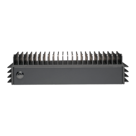
Chapter 1: Introduction 1.2 System Features The following views of the system display the main features. Refer to Appendix B for additional specifications. Front View Power LED Drive Activity LED Power Button Figure 1-1. Front View System Features: Front Feature Description The main power switch applies or removes primary power from the power supply to the Power Button... -
Page 9: Rear View
Chapter 1: Introduction Rear View Display Port USB3.2 Ports USB2.0 Port K-slot 2.5 GbE LAN Ports Lockable Power Input HDMI 2.0 Port USB3.2 Port USB Type C Ports Figure 1-2. System: Rear View System Features: Rear Feature Description The main power switch applies or removes primary power from the power supply to the Power Input server but maintains standby power. -
Page 10: Motherboard Layout
Chapter 1: Introduction 1.3 Motherboard Layout Below is a layout of the X13SAV-PS motherboard with jumper, connector and LED locations shown. See the table on the following page for descriptions. For detailed descriptions, pinout information and jumper settings, refer to Chapter 4 or the Motherboard... -
Page 11: Quick Reference Table
Chapter 1: Introduction Quick Reference Table Jumper Description Default Setting JBT1 CMOS Clear Open (Normal) JI2C1, JI2C2 SMB to PCIe Slots Enable/Disable Pins 2-3 (Disabled) JPAC1 Audio Enable Pins 1-2 (Enabled) JPME2 ME Manufacturing Mode Pins 1-2 (Normal) JPT1 Onboard TPM Module Enable/Disable Pins 1-2 (Enabled) Pins 2-4 (Low active) SIM DETECT... - Page 12 Chapter 1: Introduction Connector Description JTPM1 Trusted Platform Module/Port 80 Connector LAN1, LAN2 2.5 GbE LAN Ports MH1–MH4 Mounting Holes SLOT7 PCIe 4.0 x4 Slot USB0 Back Panel USB 2.0 Port USB1/2, 3/4 Front Accessible USB 2.0 Ports USB5/6/7/8/9 Front Accessible USB 3.2 Gen 2 x1 Ports (USB6/8: DisplayPort/USB3.2)
-
Page 13: System Block Diagram
Chapter 1: Introduction System Block Diagram PCIe4.0_x4 PCIe x4 SLOT SVID 16.0GT/s IMVP9.1 PCIe4.0_x4 INTEL LGA1700 M.2 2280 16.0GT/s M key DDR5 (CHA) DIMMA1 4800MHz Digital port 1 DDI 0 DDR5 (CHB) DIMMB1 4800MHz HDMI 2.0b Digital port 2 DDI 1 SN65DP159 SODIMM,Vertical type Type-C... -
Page 14: Chapter 2 Server Installation
Chapter 2: Server Installation Chapter 2 Server Installation 2.1 Overview This chapter provides advice and instructions for mounting your system in a server rack. If your system is not already fully integrated with processors, system memory, etc., refer to Chapter 3 for details on installing those components. -
Page 15: Rack Precautions
Chapter 2: Server Installation Rack Precautions • Verify that the leveling jacks on the bottom of the rack are extended to the floor so that the full weight of the rack rests on them. • In single-rack installations, stabilizers should be attached to the rack. In multi-rack installations, the racks should be coupled together. -
Page 16: Airflow
Chapter 2: Server Installation Airflow Equipment should be mounted into a rack so that the amount of airflow required for safe operation is not compromised. Mechanical Loading Equipment should be mounted into a rack so that a hazardous condition does not arise due to uneven mechanical loading. -
Page 17: Adding Components To Your System
Chapter 2: Server Installation Adding Components to your System • Memory: If your system is not already fully integrated with system memory, refer to Chapter 3 for details on compatible types of memory and the installation procedure. • Drives and Storage: To add storage capabilities to your server, see Chapter •... -
Page 18: Mounting On A Wall
Chapter 2: Server Installation 2.3 Mounting on a Wall The chassis can be mounted on a wall using a bracket (optional, MCP-290-30201-0B). 1. Secure the bracket to the wall where you want the server to be mounted by using four screws through the holes around the center of the bracket, as shown below. - Page 19 Chapter 2: Server Installation 3. With the input/output ports facing up, hang the server on the mounting bracket by hooking the four keyholes on the bottom of the chassis on the four knobs of the bracket. Figure 2-3. Hanging Server on the Bracket 4.
- Page 20 Chapter 2: Server Installation 6. The power adapter can be secured to this lower bracket by partially unscrewing its latch, sliding the latch upward, placing the power adapter in the bracket, lowering the latch, and tightening the screw to secure it in place. Power Adapter Bracket Latch Screw of Power Adapter Bracket Latch Figure 2-5.
-
Page 21: Chapter 3 Maintenance And Component Installation
Chapter 3 Maintenance and Component Installation Chapter 3 Maintenance and Component Installation This chapter provides instructions on installing and replacing main system components. To prevent compatibility issues, only use components that match the specifications and/or part numbers given. Installation or replacement of most components require that power first be removed from the system. -
Page 22: Accessing The System
Chapter 3 Maintenance and Component Installation 3.2 Accessing the System The CSE-E302iL3 features a removable top cover to access the inside of the chassis. Screws Screws Figure 3-1. Removing the Chassis Cover Removing the Top Cover 1. Power down the system as described in Section 3.1. -
Page 23: Static-Sensitive Devices
Chapter 3 Maintenance and Component Installation 3.3 Static-Sensitive Devices Electrostatic Discharge (ESD) can damage electronic com ponents. To avoid damaging your motherboard, it is important to handle it very carefully. The following measures are generally sufficient to protect the system PCBs from ESD. Precautions •... -
Page 24: Memory Support And Installation
Chapter 3 Maintenance and Component Installation 3.4 Memory Support and Installation Note: Check the Supermicro website for recommended memory modules. Important: Exercise extreme care when installing or removing DIMM modules to prevent any possible damage. Memory Support The X13SAV-PS supports up to 64 GB of DDR5 Non-ECC SODIMM memory with speeds of up to 4800 MT/s in the DIMMB1 memory slot. -
Page 25: General Guidelines For Optimizing Memory Performance
Chapter 3 Maintenance and Component Installation General Guidelines for Optimizing Memory Performance • Only the DIMMB1 memory slot may be populated. PCB EDGE PCB EDGE PCB EDGE PCB EDGE PCB EDGE PCB EDGE PCB EDGE JSPKR1 USB0 USB6/7 USB8/9 HDMI2.0B USB5 (3.2) LAN2 LAN1... -
Page 26: Dimm Installation
Chapter 3 Maintenance and Component Installation DIMM Installation Warning! Due to thermal limitations, SYS-E302-13AD only supports DIMMB1 slot. 1. Install the SODIMM into the DIMMB1 memory slot. 2. Align the key on the bottom of the SODIMM module against the receptive point on the memory slot. -
Page 27: Chassis Components
Chapter 3 Maintenance and Component Installation 3.5 Chassis Components Installing the Storage Drive The CSE-E302iL3 can accommodate one fixed 2.5" storage drive of 7-mm height, installed to the chassis bottom. Figure 3-4. Installing the Storage Drive... -
Page 28: Chapter 4 Motherboard Connections
Chapter 4 Motherboard Connections Chapter 4 Motherboard Connections This section describes the connections on the X13SAV-PS motherboard and provides pinout definitions. Note that depending on how the system is configured, not all connections are required. The LEDs on the motherboard are also described here. A motherboard layout indicating component locations may be found in Chapter Please review the Safety Precautions in Appendix A before installing or removing components. -
Page 29: Headers And Connectors
Chapter 4 Motherboard Connections 4.2 Headers and Connectors Fan Headers There are three 4-pin fan headers on the motherboard. Although pins 1-3 of the fan headers are backward compatible with the traditional 3-pin fans, we recommend you use 4-pin fans to take advantage of the fan speed control via Pulse Width Modulation through the thermal management. - Page 30 Port 80 connection. Use this header to enhance system performance and data security. Refer to the table below for pin definitions. Go to the following link for more information on the TPM: http://www.supermicro.com/manuals/other/TPM.pdf. Disable the Onboard TPM 2.0 function before adding an AOC TPM module.
- Page 31 Chapter 4 Motherboard Connections SATA Port The motherboard has two SATA 3.0 ports supported by the CPU. M.2 Slots The motherboard has three M.2 slots (JMD1, JMD2 ,and JMD3). M.2 was formerly known as Next Generation Form Factor (NGFF) and serves to replace mini PCIe. M.2 allows for a variety of card sizes, increased functionality, and spatial efficiency.
- Page 32 Chapter 4 Motherboard Connections Front Panel Audio Header A 10-pin front panel audio header (Audio FP) located on the motherboard allows you to use the onboard sound for audio playback. Connect an audio cable to the header to use this feature.
-
Page 33: Control Panel
JF1 contains header pins for various buttons and indicators that are normally located on a control panel at the front of the chassis. These connectors are designed specifically for use with Supermicro chassis. See the figure below for the descriptions of the front control panel buttons and LED indicators. - Page 34 Chapter 4 Motherboard Connections Power Button The Power Button connection is located on pins 1 and 2 of JF1. Momentarily contacting both pins will power on/off the system. This button can also be configured to function as a suspend button (with a setting in the BIOS -- see X13SAV-PS manual).
- Page 35 Chapter 4 Motherboard Connections NIC1/NIC2 (LAN1/LAN2) The Network Interface Controller (NIC) LED connection for LAN port 1 is located on pins 11 and 12 of JF1, and LAN port 2 is on pins 9 and 10. Attach the NIC LED cables here to display network activity.
-
Page 36: Ports
Chapter 4 Motherboard Connections 4.3 Ports See figure below for the locations and descriptions of the various I/O ports on the rear of the motherboard. PCB EDGE PCB EDGE PCB EDGE PCB EDGE PCB EDGE PCB EDGE PCB EDGE JSPKR1 USB0 USB6/7 USB8/9... - Page 37 Chapter 4 Motherboard Connections HDMI and DP Port One High Definition Multimedia Interface (HDMI) port is on the I/O back panel. This connector is used to display both high definition video and digital sound through an HDMI-capable display. HDMI 2.0 allows faster frame rates and is backward compatbile with previous HDMI versions.
-
Page 38: Jumpers
Chapter 4 Motherboard Connections 4.4 Jumpers How Jumpers Work To modify the operation of the motherboard, jumpers are used to choose between optional settings. Jumpers create shorts between two pins to change the function associated with it. Pin 1 is identified with a square solder pad on the printed circuit board. See the motherboard layout page for jumper locations. - Page 39 Chapter 4 Motherboard Connections Watchdog Timer Watchdog (JWD1) is a system monitor that can reboot the system when a software application hangs. Close pins 1-2 to reset the system if an application hangs. Close pins 2-3 to generate a non-maskable interrupt (NMI) signal for the application that hangs. Refer to the table below for jumper settings.
- Page 40 Chapter 4 Motherboard Connections SMBus to PCIe Slots Use jumpers JI C1 and JI C2 to enable PCIe System Management Bus (SMB) support to improve system management for the onboard PCIe slot. SMBus to PCIe Slots Jumper Settings Jumper Setting Definition Pins 1-2 Enabled...
-
Page 41: Led Indicators
Chapter 4 Motherboard Connections 4.5 LED Indicators LAN LEDs Two LAN ports (LAN 1/2) are located on the I/O back panel of the motherboard. Each Ethernet LAN port has two LEDs. The green LED indicates activity, while the other Link LED may be green, amber, or off to indicate the speed of the connection. -
Page 42: Chapter 5 Software
1. Create a method to access the MS Windows installation ISO file. That can be a USB flash or media drive. 2. Retrieve the proper RST/RSTe driver. Go to the Supermicro web page for your motherboard and click on "Download the Latest Drivers and Utilities," select the proper driver, and copy it to a USB flash drive. - Page 43 Chapter 5: Software 4. During Windows Setup, continue to the dialog where you select the drives on which to install Windows. If the disk you want to use is not listed, click on “Load driver” link at the bottom left corner. Figure 5-2.
-
Page 44: Driver Installation
The Supermicro website contains drivers and utilities for your system at https://www. supermicro.com/wdl/driver. Some of these must be installed, such as the chipset driver. After accessing the website, go into the CDR_Images (in the parent directory of the above link) and locate the ISO file for your motherboard. Download this file to a USB flash or media drive. -
Page 45: Superdoctor® 5
Chapter 5: Software 5.3 SuperDoctor® 5 The Supermicro SuperDoctor 5 is a program that functions in a command-line or web-based interface for Windows and Linux operating systems. The program monitors such system health information as CPU temperature, system voltages, system power consumption, fan speed, and provides alerts via email or Simple Network Management Protocol (SNMP). -
Page 46: Appendix A Standardized Warning Statements For Ac Systems
Supermicro's Technical Support department for assistance. Only certified technicians should attempt to install or configure components. Read this appendix in its entirety before installing or configuring components in the Supermicro chassis. These warnings may also be found on our website at http://www.supermicro.com/about/... - Page 47 Appendix A: Warning Statements Warnung WICHTIGE SICHERHEITSHINWEISE Dieses Warnsymbol bedeutet Gefahr. Sie befinden sich in einer Situation, die zu Verletzungen führen kann. Machen Sie sich vor der Arbeit mit Geräten mit den Gefahren elektrischer Schaltungen und den üblichen Verfahren zur Vorbeugung vor Unfällen vertraut. Suchen Sie mit der am Ende jeder Warnung angegebenen Anweisungsnummer nach der jeweiligen Übersetzung in den übersetzten Sicherheitshinweisen, die zusammen mit diesem Gerät ausgeliefert wurden.
- Page 48 Appendix A: Warning Statements . ٌ ا ك ً ف حالة و ٌ يك أى تتسبب ف اصابة جسذ ة ٌ هذا الزهز ع ٌ خطز !تحذ ز قبل أى تعول عىل أي هعذات،يك عىل علن بالوخاطز ال ا ٌجوة عي الذوائز ٍ...
- Page 49 Appendix A: Warning Statements Warnung Vor dem Anschließen des Systems an die Stromquelle die Installationsanweisungen lesen. ¡Advertencia! Lea las instrucciones de instalación antes de conectar el sistema a la red de alimentación. Attention Avant de brancher le système sur la source d'alimentation, consulter les directives d'installation. .יש...
- Page 50 Appendix A: Warning Statements Warnung Dieses Produkt ist darauf angewiesen, dass im Gebäude ein Kurzschluss- bzw. Überstromschutz installiert ist. Stellen Sie sicher, dass der Nennwert der Schutzvorrichtung nicht mehr als: 250 V, 20 A beträgt. ¡Advertencia! Este equipo utiliza el sistema de protección contra cortocircuitos (o sobrecorrientes) del edificio.
- Page 51 Appendix A: Warning Statements Power Disconnection Warning Warning! The system must be disconnected from all sources of power and the power cord removed from the power supply module(s) before accessing the chassis interior to install or remove system components (except for hot-swap components). 電源切断の警告...
- Page 52 Appendix A: Warning Statements אזהרה מפני ניתוק חשמלי !אזהרה יש לנתק את המערכת מכל מקורות החשמל ויש להסיר את כבל החשמלי מהספק .לפני גישה לחלק הפנימי של המארז לצורך התקנת או הסרת רכיבים يجب فصم اننظاو من جميع مصادر انطاقت وإ ز انت سهك انكهرباء من وحدة امداد انطاقت...
- Page 53 Appendix A: Warning Statements Attention Seul le personnel autorisé et le personnel de maintenance qualifié doivent être autorisés à installer, remplacer ou entretenir cet équipement.. !אזהרה .יש לאפשר רק צוות מורשה ואנשי שירות מוסמכים להתקין, להחליף או לטפל בציוד זה .ينبغي...
- Page 54 Appendix A: Warning Statements Warnung Diese Einheit ist zur Installation in Bereichen mit beschränktem Zutritt vorgesehen. Der Zutritt zu derartigen Bereichen ist nur mit einem Spezialwerkzeug, Schloss und Schlüssel oder einer sonstigen Sicherheitsvorkehrung möglich. ¡Advertencia! Esta unidad ha sido diseñada para instalación en áreas de acceso restringido. Sólo puede obtenerse acceso a una de estas áreas mediante la utilización de una herramienta especial, cerradura con llave u otro medio de seguridad.
- Page 55 Appendix A: Warning Statements Battery Handling Warning! There is the danger of explosion if the battery is replaced incorrectly. Replace the battery only with the same or equivalent type recommended by the manufacturer. Dispose of used batteries according to the manufacturer's instructions 電池の取り扱い...
- Page 56 Appendix A: Warning Statements هناك خطر من انفجار يف حالة اسحبذال البطارية بطريقة غري صحيحة فعليل اسحبذال البطارية فقط بنفس النىع أو ما يعادلها مام أوصث به الرشمة املصنعة جخلص من البطاريات املسحعملة وفقا لحعليامت الرشمة الصانعة 경고! 배터리가 올바르게 교체되지 않으면 폭발의 위험이 있습니다. 기존 배터리와 동일하거나 제 조사에서...
- Page 57 Appendix A: Warning Statements ¡Advertencia! Puede que esta unidad tenga más de una conexión para fuentes de alimentación. Para cortar por completo el suministro de energía, deben desconectarse todas las conexiones. Attention Cette unité peut avoir plus d'une connexion d'alimentation. Pour supprimer toute tension et tout courant électrique de l'unité, toutes les connexions d'alimentation doivent être débranchées.
- Page 58 Appendix A: Warning Statements Backplane Voltage Warning! Hazardous voltage or energy is present on the backplane when the system is operating. Use caution when servicing. バックプレーンの電圧 システムの稼働中は危険な電圧または電力が、 バックプレーン上にかかっています。 修理する際には注意く ださい。 警告 当系统正在进行时,背板上有很危险的电压或能量,进行维修时务必小心。 警告 當系統正在進行時,背板上有危險的電壓或能量,進行維修時務必小心。 Warnung Wenn das System in Betrieb ist, treten auf der Rückwandplatine gefährliche Spannungen oder Energien auf.
- Page 59 Appendix A: Warning Statements هناك خطز مه التيار الكهزبايئ أوالطاقة املىجىدة عىل اللىحة عندما يكىن النظام يعمل كه حذ ر ا عند خدمة هذا الجهاس 경고! 시스템이 동작 중일 때 후면판 (Backplane)에는 위험한 전압이나 에너지가 발생 합니다. 서비스 작업 시 주의하십시오. Waarschuwing Een gevaarlijke spanning of energie is aanwezig op de backplane wanneer het systeem in gebruik is.
- Page 60 Appendix A: Warning Statements תיאום חוקי החשמל הארצי !אזהרה .התקנת הציוד חייבת להיות תואמת לחוקי החשמל המקומיים והארציים تركيب املعدات الكهربائية يجب أن ميتثل للقىاويه املحلية والىطىية املتعلقة بالكهرباء 경고! 현 지역 및 국가의 전기 규정에 따라 장비를 설치해야 합니다. Waarschuwing Bij installatie van de apparatuur moet worden voldaan aan de lokale en nationale elektriciteitsvoorschriften.
- Page 61 Appendix A: Warning Statements Attention La mise au rebut ou le recyclage de ce produit sont généralement soumis à des lois et/ou directives de respect de l'environnement. Renseignez-vous auprès de l'organisme compétent. סילוק המוצר !אזהרה .סילוק סופי של מוצר זה חייב להיות בהתאם להנחיות וחוקי המדינה التخلص...
- Page 62 Appendix A: Warning Statements Warnung Gefährlich Bewegende Teile. Von den bewegenden Lüfterblätter fern halten. Die Lüfter drehen sich u. U. noch, wenn die Lüfterbaugruppe aus dem Chassis genommen wird. Halten Sie Finger, Schraubendreher und andere Gegenstände von den Öffnungen des Lüftergehäuses entfernt.
- Page 63 Verbindungskabeln, Stromkabeln und/oder Adapater, die Ihre örtlichen Sicherheitsstandards einhalten. Der Gebrauch von anderen Kabeln und Adapter können Fehlfunktionen oder Feuer verursachen. Die Richtlinien untersagen das Nutzen von UL oder CAS zertifizierten Kabeln (mit UL/CSA gekennzeichnet), an Geräten oder Produkten die nicht mit Supermicro gekennzeichnet sind.
- Page 64 .قيرح وأ لطع يف ببستي دق ىرخأ تالوحمو تالباك يأ مادختسا .ميلسلا سباقلاو لصوملا مجح لبق نم ةدمتعملا تالباكلا مادختسا تادعملاو ةيئابرهكلا ةزهجألل ةمالسلا نوناق رظحيUL وأCSA ( ةمالع لمحت يتلاوUL/CSA) لبق نم ةددحملاو ةينعملا تاجتنملا ريغ ىرخأ تادعم يأ عمSupermicro.
- Page 65 사항을 준수하여 제공되거나 지정된 연결 혹은 구매 케이블, 전원 케이블 및 AC 어댑터를 사용하십시오. 다른 케이블이나 어댑터를 사용하면 오작동이나 화재가 발생할 수 있습니다. 전기 용품 안전법은 UL 또는 CSA 인증 케이블 (코드에 UL / CSA가 표시된 케이블)을 Supermicro 가 지정한 제품 이외의 전기 장치에 사용하는 것을 금지합니다. Stroomkabel en AC-Adapter...
-
Page 66: Appendix B System Specifications
Appendix B: System Specifications Appendix B System Specifications Processors Supports an Intel Gen Core i3/i5/i7/Celeron UL or HL series, and Celeron processors up to 65 W in an LGA1700 socket ® Note: A maximum of five CPU replacements may be performed without an SPI re-flash/replacement needed. Chipset Intel®... - Page 67 Appendix B: System Specifications EMC/EMI: 2014/30/EU (EMC Directive) FCC Part 15 Subpart B ICES-003 VCCI-CISPR 32 AS/NZS CISPR 32 EN/BS EN55032 EN/BS EN55035 CISPR 32 CISPR 35 EN/BS 61000-3-2 EN/BS 61000-3-3 EN/BS 61000-4-2 EN/BS 61000-4-3 EN/BS 61000-4-4 EN/BS 61000-4-5 EN/BS 61000-4-6 EN/BS 61000-4-8 EN/BS 61000-4-11 Green Environment:...
-
Page 68: Bsmi/Rohs
Appendix B: System Specifications BSMI/RoHS 限 限 用 用 物 物 質 質 含 含 有 有 情 情 況 況 標 標 示 示 聲 聲 明 明 書 書 Declaration of the Presence Condition of the Restricted Substances Marking 設備名稱:嵌入式系統/ Embedded System Equipment name E302iL-A18X13 (系列型號: E302- 18 , SYS-E302-13AD ) - Page 69 Appendix B: System Specifications 警告: 為避免電磁干擾, 本產品不應安裝或使用於住宅環境。 輸入額定 *使用者不能任意拆除或替換內部配備 *報驗義務人之姓名或名稱:美超微電腦股份有限公司 *報驗義務人之地址:新北市中和區建一路 150 號 3 樓...
Need help?
Do you have a question about the SuperServer SYS-E302-13AD and is the answer not in the manual?
Questions and answers