Ruijie Reyee RG-NIS3100 Series Hardware Installation And Reference Manual
Hide thumbs
Also See for Reyee RG-NIS3100 Series:
- Hardware installation and reference manual (46 pages)

Related Manuals for Ruijie Reyee RG-NIS3100 Series


Summary of Contents for Ruijie Reyee RG-NIS3100 Series
- Page 1 RG-NIS3100 Series Switches Hardware Installation and Reference Guide Document Version: V1.1 Date: 2023-11-08 Copyright © 2023 Ruijie Networks...
- Page 2 Ruijie Networks reserves the right to modify the content of the document without any notice or prompt. This manual is designed merely as a user guide. Ruijie Networks has tried its best to ensure the accuracy and reliability of the content when compiling this manual, but it does not guarantee that the content of the manual is completely free of errors or omissions, and all the information in this manual does not constitute any explicit or implicit warranties.
- Page 3 Intended Audience This document is intended for: Network engineers Technical support and servicing engineers Network administrators Technical Support The official website of Ruijie Reyee: https://www.ruijienetworks.com/products/reyee Technical Support Website: https://www.ruijienetworks.com/support Case Portal: https://caseportal.ruijienetworks.com Community: https://community.ruijienetworks.com...
- Page 4 Note This manual provides the device installation steps, hardware troubleshooting, module technical specifications, and specifications and usage guidelines for cables and connectors. It is intended for the users who have some experience in installing and maintaining network hardware. At the same time, it is assumed that the users are already familiar with the related terms and concepts.
-
Page 5: Product Introduction
It features industrial-grade operating temperature range and professional outdoor surge protection capabilities, and complies with enterprise-class dustproof and anticorrosion standards, adapting to harsh and complex outdoor cabinet scenarios. In addition, with the Ruijie's exclusive Self-Organizing Network (SON) technology and the unified management platform Ruijie Cloud, the switch facilitates easy management and O&M. - Page 6 DDR3 256 MB Optical Module See Appendix B. Copper cables are not supported. Note The supported module types may update without prior notice. Please contact Ruijie Networks for details. SFP Port The SFP port supports 1000BASE-X and 100BASE-FX. Power Supply...
- Page 7 RG-NIS3100 Series Switches Hardware Installation and Reference Guide Product Introduction PoE Power Cable Mode A (1-2 and 3-6 pairs) Pairs Max. Power Without PoE load: 20 W Consumption With full PoE load: 80 W (input voltage: 12 V to 20 V) 140 W (input voltage: 21 V to 45 V) 260 W (input voltage: 46 V to 56 V) Long-term...
- Page 8 RG-NIS3100 Series Switches Hardware Installation and Reference Guide Product Introduction Caution ● In a domestic environment, this product may cause radio interference in which case the user may be required to take adequate measures. ● To ensure minimal radio interference and the compatibility with various power module models, it is necessary to use a power cord (less than 3 meters) with a magnetic ring larger than 7 Ohm at the input end of the device.
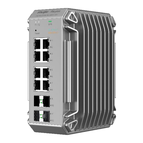
- Page 9 RG-NIS3100 Series Switches Hardware Installation and Reference Guide Product Introduction 1. Front Panel Figure 1-2 Front Panel of RG-NIS3100-8GT4SFP-HP Note 1. Power status LED P1 5. 10/100/1000BASE-T Ethernet ports with auto-negotiation 2. Power status LED P2 6. GE SFP ports 3.
- Page 10 RG-NIS3100 Series Switches Hardware Installation and Reference Guide Product Introduction is upgrading. Irregular blinking green (cycle: 1s on and 1s off, The main program is lost or 0.25s on and 0.25s off, damaged, or specific functions are 0.25s on and 0.25s off, abnormal.
- Page 11 RG-NIS3100 Series Switches Hardware Installation and Reference Guide Product Introduction Note 1. Grounding stud 2. DC power inlet PWR2 3. Alarm port 4. DC power inlet PWR1 Information ● The alarm port contact operates in a closed state under normal conditions. When a triggering alarm event occurs (such as a power loss in one of the two power sources), the contact switches to an open state.
- Page 12 RG-NIS3100 Series Switches Hardware Installation and Reference Guide Product Introduction Figure 1-5 Rear Panel for Wall Mounting Note 1. DIN rail clamp 2. Screw holes for wall mounting Note To maintain the IP40 state of the device, fix the two screws back into their original positions in the DIN slot when mounting the device on a wall.
- Page 13 SDRAM DDR3 256 MB Optical Module See Appendix B. Copper cables are not supported. The supported module types may update without prior notice. Please contact Ruijie Networks for details. SFP Port The SFP port supports 1000BASE-X and 100BASE-FX. Power Supply...
- Page 14 RG-NIS3100 Series Switches Hardware Installation and Reference Guide Product Introduction Max. Power Without PoE load: 20 W Consumption With full PoE load: 60 W (input voltage: 12 V to 20 V) 120 W (input voltage: 21 V to 45 V) 240 W (input voltage: 46 V to 56 V) Long-term -40º...
- Page 15 RG-NIS3100 Series Switches Hardware Installation and Reference Guide Product Introduction of the device. This ensures electromagnetic compatibility and proper functioning of the device. Moreover, you are advised to use shielded twisted pair (STP) cables for Ethernet port connections. Danger This device is not suitable for use in locations where children are likely to be present. 1.4.2 Appearance The RG-NIS3100-8GT2SFP-HP full GE switch provides eight 10/100/1000BASE-T RJ45 ports with...
- Page 16 RG-NIS3100 Series Switches Hardware Installation and Reference Guide Product Introduction 2. Front Panel Figure 1-8 Front Panel of RG-NIS3100-8GT2SFP-HP Note 1. Power status LED P1 5. 10/100/1000BASE-T Ethernet ports with auto-negotiation 2. Power status LED P2 6. GE SFP ports 3.
- Page 17 RG-NIS3100 Series Switches Hardware Installation and Reference Guide Product Introduction The switch is restoring factory Blinking green (2 Hz) settings and will be powered off or is upgrading. Irregular blinking green (cycle: 1s on and 1s off, The main program is lost or 0.25s on and 0.25s off, damaged, or specific functions are 0.25s on and 0.25s off,...
- Page 18 RG-NIS3100 Series Switches Hardware Installation and Reference Guide Product Introduction Note 1. Grounding stud 2. DC power inlet PWR2 3. Alarm port 4. DC power inlet PWR1 Information ● The alarm port contact operates in a closed state under normal conditions. When a triggering alarm event occurs (such as a power loss in one of the two power sources), the contact switches to an open state.
- Page 19 RG-NIS3100 Series Switches Hardware Installation and Reference Guide Product Introduction Figure 1-11 Rear Panel for Wall Mounting Note 1. DIN rail clamp 2. Screw holes for wall mounting Note To maintain the IP40 state of the device, fix the two screws back into their original positions in the DIN slot when mounting the device on a wall.
- Page 20 SDRAM DDR3 256 MB Optical Module See Appendix B. Copper cables are not supported. The supported module types may update without prior notice. Please contact Ruijie Networks for details. SFP Port The SFP port supports 1000BASE-X and 100BASE-FX. Power Supply...
- Page 21 RG-NIS3100 Series Switches Hardware Installation and Reference Guide Product Introduction Ground-Leakage ≤ 3.5 mA Current Supported All RJ45 ports are PoE capable and each port provides up to 30 W of PoE power. Maximum overall PoE/PoE+ output power: 120 W The PoE port is PoE/PoE+ capable.
- Page 22 RG-NIS3100 Series Switches Hardware Installation and Reference Guide Product Introduction Dimensions (W × D 85 mm x 132 mm x 165 mm (3.35 in. x 5.20 in. x 6.50 in.) × H) Weight 1.39 kg (3.06 lbs.) Caution ● In a domestic environment, this product may cause radio interference in which case the user may be required to take adequate measures.
- Page 23 RG-NIS3100 Series Switches Hardware Installation and Reference Guide Product Introduction 2. Front Panel Figure 1-14 Front Panel of RG-NIS3100-4GT2SFP-HP Note 1. Power status LED P1 5. 10/100/1000BASE-T Ethernet ports with auto-negotiation 2. Power status LED P2 6. GE SFP ports 3.
- Page 24 RG-NIS3100 Series Switches Hardware Installation and Reference Guide Product Introduction Slow blinking green The switch is not connected to the (0.5 Hz) cloud. The switch is restoring factory Blinking green (2 Hz) settings and will be powered off or is upgrading. Irregular blinking green (cycle: 1s on and 1s off, The main program is lost or...
- Page 25 RG-NIS3100 Series Switches Hardware Installation and Reference Guide Product Introduction 4. Top Panel Figure 1-15 Top Panel of RG-NIS3100-4GT2SFP-HP Note 1. Grounding stud 2. DC power inlet PWR2 3. Alarm port 4. DC power inlet PWR1 Information ● The alarm port contact operates in a closed state under normal conditions. When a triggering alarm event occurs (such as a power loss in one of the two power sources), the contact switches to an open state.
- Page 26 RG-NIS3100 Series Switches Hardware Installation and Reference Guide Product Introduction Figure 1-17 Rear Panel for Wall Mounting Note 1. DIN rail clamp 2. Screw holes for wall mounting Note To maintain the IP40 state of the device, fix the two screws back into their original positions in the DIN slot when mounting the device on a wall.
- Page 27 RG-NIS3100 Series Switches Hardware Installation and Reference Guide Product Introduction 6. Bottom Panel Figure 1-18 Bottom Panel of NIS3100-4GT2SFP-HP Note 1. Nameplate 7. Cooling The RG-NIS3100-4GT2SFP-HP adopts natural cooling to ensure that the device works properly under specified environment. Maintain a minimum clearance of 100 mm (3.94 in.) around the device to ensure proper ventilation.
-
Page 28: Preparation Before Installation
RG-NIS3100 Series Switches Hardware Installation and Reference Guide Preparation before Installation Preparation before Installation Safety Suggestions To avoid personal injury and device damage, carefully read the safety suggestions before you install the RG-NIS3100 series. The following safety suggestions may not cover all possible dangers. 2.1.1 General Safety Precautions ... - Page 29 RG-NIS3100 Series Switches Hardware Installation and Reference Guide Preparation before Installation If a power supply system is equipped with a leakage protector (leakage current switch or breaker), the rated leakage action current of each leakage protector is twice greater than the maximum leakage current of all the power supplies in the system.
-
Page 30: Installation Site Requirements
RG-NIS3100 Series Switches Hardware Installation and Reference Guide Preparation before Installation Installation Site Requirements To ensure the normal running and prolonged service life of the device, the installation site must meet the following requirements. 2.2.1 Load Bearing Requirements Evaluate the load bearing requirements for the ground according to the weight of the switch and its accessories (such as the cabinet, chassis, line cards and power supply modules). - Page 31 RG-NIS3100 Series Switches Hardware Installation and Reference Guide Preparation before Installation get rusted. In an environment with a low humidity, insulating strips may dry and shrink. Static electricity may occur easily and endanger circuits on the device. In an environment with a high temperature, the router is subject to more serious harm. Its performance may degrade significantly and various hardware faults may occur.
- Page 32 RG-NIS3100 Series Switches Hardware Installation and Reference Guide Preparation before Installation 2.2.7 Grounding A good grounding system is the basis for stable and reliable operation of the device, preventing lightning strokes and resisting interference. Carefully check the grounding conditions at the installation site according to the grounding requirements, and perform grounding operations properly as required.
-
Page 33: Lightning Resistance
RG-NIS3100 Series Switches Hardware Installation and Reference Guide Preparation before Installation Figure 2-2 Grounding of the RG-NIS3100 Series Switch Grounding stud 2.2.8 Electro-Magnetic Interference (EMI), from either outside or inside the device or application system, affects the system in the conductive ways such as capacitive coupling, inductive coupling, and electromagnetic radiation. There are two types of electromagnetic interference: radiated interference and conducted interference, depending on the type of the transmission path. -
Page 34: Installation Tools
RG-NIS3100 Series Switches Hardware Installation and Reference Guide Preparation before Installation Installation Tools Phillips screwdriver, flathead screwdriver, related electric cables and optical Common Tools cables, bolts, diagonal pliers, and straps Special Tools Anti-static tools Meters Multimeter The tool kit is customer-supplied. -
Page 35: Product Installation
RG-NIS3100 Series Switches Hardware Installation and Reference Guide Product Installation Product Installation Ensure that you have read chapter 2 carefully. Verify that the requirements described in chapter 2 have been met. Installation Flowchart Install the switch in place correctly Ground the switch Connect the power module Connect external interface cables... -
Page 36: Mounting The Switch On A Din Rail
RG-NIS3100 Series Switches Hardware Installation and Reference Guide Product Installation Connect the power cords of different colors to the corresponding cable terminals. Ensure that the connector of the power cord is properly seated in the power connector of the switch. After plugging the power cord on the device, secure the power cord with a power cord retention clip. -
Page 37: Mounting The Switch On A Wall
RG-NIS3100 Series Switches Hardware Installation and Reference Guide Product Installation Figure 3-2 DIN Rail Mounting Step 2 3.3.2 Mounting the Switch on a Wall You can use the mounting brackets delivered with the RG-NIS3100 series switch to mount the switch on a wall. The installation procedure is as follows: Step 1: Remove the DIN rail clamp and screws from the switch, and install the mounting brackets on the switch, as shown in Figure 3-3. -
Page 38: Grounding The Switch
RG-NIS3100 Series Switches Hardware Installation and Reference Guide Product Installation Figure 3-4 Mounting Bracket Installation Step 2 For wall mounting, the switch can be mounted only on a concrete or non-flammable surface. Grounding the Switch The switch has a grounding stud on the rear panel. Connect the grounding stud to the grounding point of the rack and then connect the grounding point of the rack to the ground bar of the equipment room. - Page 39 RG-NIS3100 Series Switches Hardware Installation and Reference Guide Product Installation (2) Connect the power module to the switch, as shown in the following figure. Connecting External Interface Cables Precautions Distinguish single-mode and multi-mode fiber-optic cables and interfaces. Avoid a small bend radius at the connector. Connection Procedure (1) Connect the RJ45 connector of an Ethernet cable to the management Ethernet interface on the device, and the other end to an NM or control terminal.
-
Page 40: Bundling The Cables
RG-NIS3100 Series Switches Hardware Installation and Reference Guide Product Installation Bundling the Cables Precautions Bundle the power cords and other cables neatly. When bundling fiber-optic cables, ensure that they have natural bends or large bend radius at the connectors. Do not bundle fiber-optic cables and twisted pair cables too tightly, as this may press the cables and affect their service life and transmission performance. -
Page 41: Troubleshooting Flowchart
RG-NIS3100 Series Switches Hardware Installation and Reference Guide Troubleshooting Troubleshooting Troubleshooting Flowchart Troubleshooting Common Faults Symptom Possible Causes Solution The management interface login A password is manually configured Press the reset button to restore the default password is but it is forgotten. settings. - Page 42 RG-NIS3100 Series Switches Hardware Installation and Reference Guide Troubleshooting frames. working mode of the connected switch. Switch the Rx and Tx ends of the optical The Rx and Tx ends are module. connected reversely. Replace the optical module with one of the The interconnected optical module The optical port matched type.
-
Page 43: Appendix A Connectors And Connection Media
RG-NIS3100 Series Switches Hardware Installation and Reference Guide Appendix A Connectors and Connection Media Appendix A Connectors and Connection Media 1000BASE-T/100BASE-TX/10BASE-T Ports The 1000BASE-T/100BASE-TX/10BASE-T supports adaptation of three rates and automatic MDI/MDIX crossover at these three rates. The 1000BASE-T complies with IEEE 802.3ab, and uses the cable of 100-ohm Category-5 or Supper Category-5 UTP or STP, which can be up to 100 m. - Page 44 RG-NIS3100 Series Switches Hardware Installation and Reference Guide Appendix A Connectors and Connection Media...
-
Page 45: Appendix B Ruijie Reyee Sfp Transceiver Modules
RG-NIS3100 Series Switches Hardware Installation and Reference GuideAppendix B Ruijie Reyee SFP Transceiver Modules Appendix B Ruijie Reyee SFP Transceiver Modules Current Industrial-grade SFP Module Models and Specifications Rate Standard SFP Module Model Short wavelength NIS-GE-SFP-550M-MM850 Ethernet NIS-GE-SFP-10KM-SM1310 1000 Mbps... -
Page 46: Appendix C Surge Protection
RG-NIS3100 Series Switches Hardware Installation and Reference Guide Appendix C Surge Protection ● To keep the optical module clean, ensure that the unused ports remain capped. Current SFP Module Cabling Specifications Connector Fiber Core Size Max. Cabling Model (μm) Type Type Distance 50/125... - Page 47 RG-NIS3100 Series Switches Hardware Installation and Reference Guide Appendix C Surge Protection Figure C-1 Schematic Diagram for the Power Arrester The power arrester is not provided and customers have to purchase it. Precautions for installation: Ensure that the PE terminal of the power arrester is properly grounded. ...
- Page 48 RG-NIS3100 Series Switches Hardware Installation and Reference Guide Appendix C Surge Protection According to the Ethernet Port Arrester Hardware Installation Guide, connect the arrester using the adapter cable (note that the external network cable is connected to the end of IN, while the adapter cable connected to the switch is connected to the end of OUT) and check whether the LED on the board is normal.
-
Page 49: Appendix D Cabling Recommendations
RG-NIS3100 Series Switches Hardware Installation and Reference Guide Appendix D Cabling Recommendations Appendix D Cabling Recommendations When RG-NIS3100 series switches are installed in standard 19-inch cabinets, cables are tied in the binding rack on the cabinet by the cabling rack, and top or bottom cabling is adopted according to the actual situation in the equipment room. - Page 50 RG-NIS3100 Series Switches Hardware Installation and Reference Guide Appendix D Cabling Recommendations Route and bundle power, signal, ground cables separately. When the cables are close to each other, cross them. When power cables are parallel to signal cables, the distance between them must be 30 mm (1.18 in.). ...
- Page 51 RG-NIS3100 Series Switches Hardware Installation and Reference Guide Appendix D Cabling Recommendations Wrap up unnecessary or excess cables and bind them to the appropriate rack position, where device operation is not affected and no damages occur to the device and cables during commissioning. ...
- Page 52 RG-NIS3100 Series Switches Hardware Installation and Reference Guide Appendix D Cabling Recommendations 200 to 300 No knot is allowed in cabling or bundling. The metal parts of the cold-pressed terminal blocks, such as air circuit breakers, should not be exposed outside of the blocks.
-
Page 53: Appendix E Site Selection
RG-NIS3100 Series Switches Hardware Installation and Reference Guide Appendix E Site Selection Appendix E Site Selection The equipment room should be at least 5 km away from the heavy pollution source such as the smelter, coal mine, and thermal power plant, 3.7 km away from the medium pollution source such as the chemical industry, rubber industry, and electroplating industry, and 2 km away from the light pollution source such as the food manufacturer and leather plant.
Need help?
Do you have a question about the Reyee RG-NIS3100 Series and is the answer not in the manual?
Questions and answers