Ruijie Reyee RG-NBS3100-24GT4SFP-V2 Installation Manual
Hide thumbs
Also See for Reyee RG-NBS3100-24GT4SFP-V2:
- Release notes (10 pages) ,
- Configuration manual (297 pages)

Related Manuals for Ruijie Reyee RG-NBS3100-24GT4SFP-V2


Summary of Contents for Ruijie Reyee RG-NBS3100-24GT4SFP-V2
- Page 1 Ruijie Reyee RG-NBS3100-24GT4SFP-V2 Switch Installation Guide Document Version: V1.3 Date: May 10, 2024 Copyright © 2024 Ruijie Networks...
- Page 2 Ruijie Networks reserves the right to modify the content of the document without any notice or prompt. This manual is designed merely as a user guide. Ruijie Networks has tried its best to ensure the accuracy and reliability of the content when compiling this manual, but it does not guarantee that the content of the manual is completely free of errors or omissions, and all the information in this manual does not constitute any explicit or implicit warranties.
-
Page 3: Preface
Intended Audience This document is intended for: Network engineers Technical support and servicing engineers Network administrators Technical Support The official website of Ruijie Reyee: https://reyee.ruijie.com Technical Support Website: https://reyee.ruijie.com/en-global/support Case Portal: https://www.ruijienetworks.com/support/caseportal Community: https://community.ruijienetworks.com... - Page 4 Notes This manual presents installation instructions, troubleshooting techniques, technical specifications, cable and connector requirements, and usage guidelines. It is intended for users who want to gain insight into the above content and have some experience in installing and maintaining network hardware. It is assumed that users are already familiar with relevant terms and concepts.
-
Page 5: Table Of Contents
Contents Preface ..............................I 1 Product Overview ..........................1 1.1 RG-NBS3100-24GT4SFP-V2 ....................1 2 Preparation before Installation ......................5 2.1 Safety Suggestions ........................5 2.1.1 Installation ........................5 2.1.2 Movement ........................5 2.1.3 Electricity ........................5 2.1.4 ESD ..........................6 2.1.5 Laser .......................... - Page 6 3.3.1 Mounting the Switch to a Standard 19-inch Rack ............13 3.3.2 Mounting the Switch on a Table ................... 15 3.4 Grounding the Switch ......................15 3.5 Connecting External Cables ....................16 3.6 Bundling Cables ........................16 3.7 Checking After Installation ....................... 17 4 System Commissioning ........................
-
Page 7: Product Overview
Installation Guide Product Overview Product Overview RG-NBS3100 Series Switches 10/100/1000 1000Base-X SFP Model Console Port Power Module Base-T Ethernet Port Module Port RG-NBS3100- Single 24GT4SFP-V2 Note The SFP port is backward compatible with 100Base-FX. 1000Base-T is backward compatible with 100Base-TX and 10Base-T. RG-NBS3100-24GT4SFP-V2 Table 1-1 Package Contents... - Page 8 Installation Guide Product Overview The supported module type may change at any time. Consult Ruijie Networks for the latest information. 1000Base-X SFP Port 100Base-X AC input Rated voltage range: 100 V to 240 V Power Supply Maximum voltage range: 90 V to 264 V Frequency: 50/60 Hz Rated current: 0.6 A...
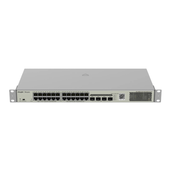
- Page 9 Installation Guide Product Overview Front Panel Figure 1-2 Front Panel of the RG-NBS3100-24GT4SFP-V2 Note: 1. System status LED 3. 10/100/1000 Base-T Ethernet port 2. Reset button 4. 1000Base-X SFP port 5. Nameplate on the bottom of the device Note The switch restarts after the reset button is pressed for less than 2 seconds.
- Page 10 Status Blinking green The switch is being upgraded or (10 Hz) initialized. Solid green The switch is connected to Ruijie Cloud. The port is not connected. 10/100/1000Base-T The port is connected at a rate of Solid green Ethernet port status 1–24...
-
Page 11: Preparation Before Installation
Installation Guide Preparation before Installation Preparation before Installation Safety Suggestions To avoid personal injury and device damage, carefully read the safety suggestions before you install the RG-NBS3100 series. Caution The following safety suggestions do not cover all possible dangers. 2.1.1 Installation ... -
Page 12: Esd
Installation Guide Preparation before Installation If a power supply system is equipped with a leakage protector (leakage current switch or breaker), the rated leakage action current of each leakage protector is twice greater than the maximum leakage current of all the power supplies in the system. For example, if a system is equipped with twenty identical power supplies, the leakage current of each power supply is equal to or less than 1.5 mA, and the total leakage current of the system is 30 mA. -
Page 13: Installation Site Requirements
Installation Guide Preparation before Installation Installation Site Requirements The installation site must meet the following requirement to ensure normal working and a prolonged durable life of the switch. 2.2.1 Ventilation For the RG-NBS3100 series, a sufficient space (at least 10 cm distance from both sides and the back plane of the cabinet) should be reserved at the ventilation openings to ensure normal ventilation. -
Page 14: Cleanness
Installation Guide Preparation before Installation 2.2.3 Cleanness Dust poses a severe threat to the running of the device. The indoor dust falling on the device may be absorbed by the static electricity, causing bad contact of the metallic joint. Such electrostatic absorption may occur more easily when the relative humidity is low. -
Page 15: Grounding
Installation Guide Preparation before Installation caused by over-voltage and over-current generated by thunder and lightning. 2.2.5 Grounding A good grounding system is the basis for stable and reliable operation of the device, preventing lightning strokes and resisting interference. Carefully check the grounding conditions at the installation site according to the grounding requirements, and perform grounding operations properly as required. -
Page 16: Lightning Resistance
Installation Guide Preparation before Installation 2.2.6 Lightning Resistance When the AC power cable is imported outdoors and directly connected to the power port of the RG-NBS3100 series switch, use the lightning line bank to prevent the switch from being hit by lightning shocks. In this case, connect the mains supply AC cable to the lightning line bank, and connect the switch to the lightning line bank. -
Page 17: Installation Tools
Installation Guide Preparation before Installation Installation Tools Table 2-4 List of Installation Tools Common Phillips screwdriver, flathead screwdriver, related electric cables and optical cables, bolts, Tools diagonal pliers, and straps Special Anti-static tools Tools Meters Multimeter Note The tool kit is customer-supplied. -
Page 18: Product Installation
Installation Guide Product Installation Product Installation Installation Flowchart Confirmations Before Installation Before installation, confirm the following points: Check whether ventilation requirements are met for the switch. Check whether the requirements of temperature and humidity are met for the switch. -
Page 19: Installing The Rg-Nbs3100
Installation Guide Product Installation Check whether power cables are already laid out and whether the requirements of electrical current are met. Check whether related network adaption lines are already laid out. Installing the RG-NBS3100 Precautions During installation, note the following points: ... - Page 20 Installation Guide Product Installation Step 2: Use the supplied M6 screws and cage nuts to securely attach the mounting brackets to the rack, as shown in Figure 3-3, Figure 3-4, Figure 3-5, and Figure 3-6. Figure 3-3 Attaching the Brackets to the Rack (8-Port Switch) Figure 3-4 Attaching the Brackets to the Rack (8-Port Switch) Figure 3-5 Attaching the Brackets to the Rack (24-Port Switch) Figure 3-6 Attaching the Brackets to the Rack (24-Port Switch)
-
Page 21: Mounting The Switch On A Table
Installation Guide Product Installation 3.3.2 Mounting the Switch on a Table Attach the four rubber pads to the recessed areas on the bottom of the switch, as shown in Figure 3-7 and Figure 3-8. Figure 3-7 Attaching the Rubber Feet to the Recessed Areas Place the switch on the table, as shown in Figure 3-8. -
Page 22: Connecting External Cables
Installation Guide Product Installation The grounding electric resistance should be less than 1 Ω. Cauiton To guarantee the security of the body and the device, the switch must be well-grounded. The grounding resistance for combined grounding should be less than 1 Ω. ... -
Page 23: Checking After Installation
Installation Guide Product Installation Checking After Installation Caution Before checking the installation, switch off the power supply so as to avoid any personal injury or damage to the component due to connection errors. Check that the ground line is connected. ... -
Page 24: System Commissioning
Installation Guide System Commissioning System Commissioning Establishing the Configuration Environment Establishing the Configuration Environment Use the network cable to connect a PC to the switch. Figure 4-1 Configuration Environment Connecting the Console Cable Connect the one end (RJ45 port) of the network cable to the network port of the PC. ... -
Page 25: Troubleshooting
Installation Guide Troubleshooting The console cable is correctly connected; the PC is already started; parameters are configured. Checking After Power-on (Recommended) After power-on, you are advised to perform the following checks to ensure the normal operation of follow-up configurations. ... -
Page 26: Troubleshooting Common Faults
Installation Guide Troubleshooting Troubleshooting Common Faults Symptom Possible Causes Solution The management interface login A password is manually configured Press the reset button to restore the default password is but it is forgotten. settings. forgotten. Check whether the power socket is normal. The status LED is The power supply is not enabled, Check whether the power cable is correctly... -
Page 27: Appendix A Connectors And Connection Media
Installation Guide Appendix A Connectors and Connection Media Appendix A Connectors and Connection Media 1000BASE-T/100BASE-TX/10BASE-T Ports The 1000BASE-T/100BASE-TX/10BASE-T supports adaptation of three rates and automatic MDI/MDIX crossover at these three rates. The 1000BASE-T complies with IEEE 802.3ab, and uses the cable of 100-ohm Category-5 or Supper Category-5 UTP or STP, which can be up to 100 m. - Page 28 Installation Guide Appendix A Connectors and Connection Media Optical Fiber Connection For the optical fiber ports, select single-mode or multimode optical fibers for connection according to the fiber module connected. Figure A-4 shows the connection schematic diagram. Figure A-4 Optical Fiber Connections...
-
Page 29: Appendix B Mini-Gbic And Spf Module
SFP modules (mini-GBIC module) and 10G SFP+ modules are available to cope with interface types of switch modules. You can select the mini-GBIC module to suit your specific needs. The models and technical specifications of some mini-GBIC and 10G SFP+ modules are listed below. For details, see Ruijie Transceiver Installation and Reference Guide. - Page 30 Installation Guide Appendix B Mini-GBIC and SPF Module -SM1550 MINI-GBIC-ZX10 1550 0-SM1550 GE-SFP-SX -9.5 GE-SFP-LX 1310 -9.5 SFP-MM850 -9.5 SFP-SM1310 1310 -9.5 Table B-2 Models and Technical Specifications of the Mini-GBIC-GT Module Standard 1000Base-T SFP Type DDM (Yes/No) 1000Base-T Mini-GBIC-GT Table B-3 Cabling Specifications of SFP Modules Maximum Media...
- Page 31 Installation Guide Appendix B Mini-GBIC and SPF Module GE-SFP-LX20-SM1550- 9/125 20 km BIDI GE-SFP-LH40-SM1310- 9/125 40 km BIDI GE-SFP-LH40-SM1550- 9/125 40 km BIDI MINI-GBIC-ZX50-SM155 9/125 50 km MINI-GBIC-ZX80-SM155 9/125 80 km MINI-GBIC-ZX100-SM15 9/125 100 km 62.5/125 275 m GE-SFP-SX 50/125 550 m GE-SFP-LX 9/125...
-
Page 32: Appendix C Surge Protection
Installation Guide Appendix C Surge Protection Appendix C Surge Protection Installing the AC Power Arrester (Surge Protection Cable Row) The external surge protection cable row must be used on the AC power port to prevent the switch from being struck by lightning when the AC power cable is introduced from the outdoor and directly connected to the power port of the switch. - Page 33 Installation Guide Appendix C Surge Protection During the switch usage, the Ethernet port arrester must be connected to the switch to prevent the switch damage by lightning before the outdoor network cable connects to the switch. Tools: cross or straight screwdriver, multimeter, and diagonal pliers Installation steps: (1) Tear one side of the protection paper for the double-sided adhesive tape and paste the tape to the framework of the Ethernet port arrester.
- Page 34 Installation Guide Appendix C Surge Protection with the switch grounding terminal. Use the multimeter to confirm the contact after grounding. Incomplete arrester installation: If more than one port is connected to the peer device on the switch, install the arresters on all connection ports for surge protection.
-
Page 35: Appendix D Cabling Recommendations
Installation Guide Appendix D Cabling Recommendations Appendix D Cabling Recommendations When RG-NBS3100 series switches are installed in standard 19-inch cabinets, cables are tied in the binding rack on the cabinet by the cabling rack, and top or bottom cabling is adopted according to the actual situation in the equipment room. - Page 36 Installation Guide Appendix D Cabling Recommendations Route and bundle power, signal, ground cables separately. When the cables are close to each other, cross them. When power cables are parallel to signal cables, the distance between them must be 30 mm (1.18 in.).
- Page 37 Installation Guide Appendix D Cabling Recommendations Wrap up unnecessary or excess cables and bind them to the appropriate rack position, where device operation is not affected and no damages occur to the device and cables during commissioning. Do not bind power cords to the rails for moving parts. ...
-
Page 38: Appendix E Site Selection
Installation Guide Appendix E Site Selection Diameter of Cable Bundle (mm) Space Between Bundles (mm) 80 to 150 10 to 30 150 to 200 200 to 300 No knot is allowed in cabling or bundling. The metal parts of the cold-pressed terminal blocks, such as air circuit breakers, should not be exposed outside of the blocks. - Page 39 Installation Guide Appendix E Site Selection Sulfur-containing materials are forbidden. Pay attention to the location of the air conditioner. Keep the air conditioner from blowing wind straight toward the device or blowing water drops from the window or air vent toward the device.
Need help?
Do you have a question about the Reyee RG-NBS3100-24GT4SFP-V2 and is the answer not in the manual?
Questions and answers