
Related Manuals for Ruijie RG-NIS3100 Series


Summary of Contents for Ruijie RG-NIS3100 Series
- Page 1 RG-NIS3100 Series Switch Hardware Installation and Reference Guide Document Version: V1.0 Date: 2023.10.12 Copyright © 2023 Ruijie Networks...
- Page 2 Ruijie Networks reserves the right to modify the content of the document without any notice or prompt. This manual is designed merely as a user guide. Ruijie Networks has tried its best to ensure the accuracy and reliability of the content when compiling this manual, but it does not guarantee that the content of the manual is completely free of errors or omissions, and all the information in this manual does not constitute any explicit or implicit warranties.
-
Page 3: Preface
Intended Audience This document is intended for: Network engineers Technical support and servicing engineers Network administrators Technical Support The official website of Ruijie Reyee: https://www.ruijienetworks.com/products/reyee Technical Support Website: https://www.ruijienetworks.com/support Case Portal: https://caseportal.ruijienetworks.com Community: https://community.ruijienetworks.com... - Page 4 Note This manual provides the device installation steps, hardware troubleshooting, module technical specifications, and specifications and usage guidelines for cables and connectors. It is intended for the users who have some experience in installing and maintaining network hardware. At the same time, it is assumed that the users are already familiar with the related terms and concepts.
-
Page 5: Table Of Contents
Contents Preface ..............................I 1 Product Overview ..........................1 1.1 Overview ............................ 1 1.2 Package Contents........................1 1.3 RG-NIS3100-8GT4SFP-HP ....................... 2 1.3.1 Technical Specifications ....................2 1.3.2 Appearance ........................4 1.4 RG-NIS3100-8GT2SFP-HP ....................... 8 1.4.1 Technical Specifications ....................8 1.4.2 Appearance ........................10 1.5 RG-NIS3100-4GT2SFP-HP ..................... - Page 6 2.3 Installation Tools ........................29 3 Installing the Switch ........................30 3.1 Installation Flowchart ....................... 30 3.2 Checking Before Installation ....................30 3.3 Installing the RG-NIS3100 ....................... 30 3.3.1 Mounting the Switch on a DIN Rail ................31 3.3.2 Mounting the Switch on a Wall ..................32 3.4 Grounding the Switch ......................
-
Page 7: Product Overview
In addition, with Ruijie's exclusive Self-Organizing Network (SON) technology and the unified management platform Ruijie Cloud, the switch enables easy management and O&M. -
Page 8: Rg-Nis3100-8Gt4Sfp-Hp
Optical Module See Appendix B. Direct Attach Copper (DAC) cables are not supported. Note The supported module types may update without prior notice. Please contact Ruijie Networks for details. SFP Port The SFP port supports 1000BASE-X and 100BASE-FX. Power Supply... - Page 9 R-NIS3100 Switch GHardware Installation and Reference Guide Product Overview Max. Power Without PoE load: 20 W Consumption With full PoE load: 60 W (input voltage: 12 V to 20 V) 120 W (input voltage: 21 V to 45 V) 240 W (input voltage: 46 V to 56 V) –40º...
-
Page 10: Appearance
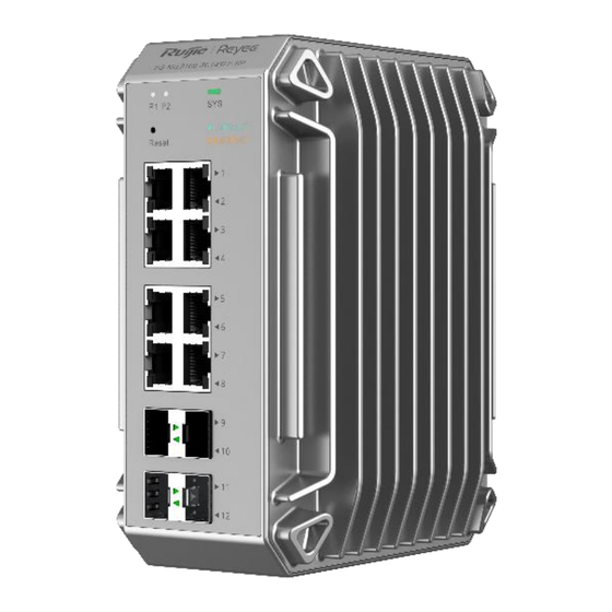
R-NIS3100 Switch GHardware Installation and Reference Guide Product Overview 1.3.2 Appearance The RG-NIS3100-8GT4SFP-HP full GE switch provides eight 10/100/1000BASE-T RJ45 ports with auto- negotiation and four SFP ports on the front panel, and DC power connectors on the top panel. The following figures show the product appearance. - Page 11 R-NIS3100 Switch GHardware Installation and Reference Guide Product Overview Reset button: Press and hold the button for less than 2 seconds to restart the system. Press and hold the button for over 5 seconds until the system status LED starts blinking to restore factory settings and restart the system.
- Page 12 R-NIS3100 Switch GHardware Installation and Reference Guide Product Overview 3. Top Panel Figure 1-3 Top Panel of NIS3100-8GT4SFP-HP 1. Grounding stud 2. DC power connector PWR2 3. Alarm port 4. DC power connector PWR1 4. Rear Panel The switch supports two installation modes: DIN rail mounting and wall mounting. Figure 1-4 Rear Panel for DIN Rail Mounting...
- Page 13 R-NIS3100 Switch GHardware Installation and Reference Guide Product Overview Figure 1-5 Rear Panel for Wall Mounting 1. DIN rail clamp 2. Mounting holes 5. Bottom Panel Figure 1-6 Bottom Panel of NIS3100-8GT4SFP-HP 1. Nameplate...
-
Page 14: Rg-Nis3100-8Gt2Sfp-Hp
SDRAM DDR3 256 MB Optical Module See Appendix B. DAC cables are not supported. The supported module types may update without prior notice. Please contact Ruijie Networks for details. SFP Port The SFP port supports 1000BASE-X and 100BASE-FX. Power Supply... - Page 15 R-NIS3100 Switch GHardware Installation and Reference Guide Product Overview Max. Power Without PoE load: 20 W Consumption With full PoE load: 60 W (input voltage: 12 V to 20 V) 120 W (input voltage: 21 V to 45 V) 240 W (input voltage: 46 V to 56 V) –40º...
-
Page 16: Appearance
R-NIS3100 Switch GHardware Installation and Reference Guide Product Overview 1.4.2 Appearance The RG-NIS3100-8GT2SFP-HP full GE switch provides eight 10/100/1000BASE-T RJ45 ports with auto- negotiation and two SFP ports on the front panel, and DC power connectors on the top panel. The following figures show the product appearance. - Page 17 R-NIS3100 Switch GHardware Installation and Reference Guide Product Overview 1. Power status LED P1 5. 10/100/1000BASE-T Ethernet ports with auto-negotiation 2. Power status LED P2 6. GE SFP ports 3. System status LED 4. Reset button Reset button: Press and hold the button for less than 2 seconds to restart the system. Press and hold the button for over 5 seconds until the system status LED starts blinking to restore factory settings and restart the system.
- Page 18 R-NIS3100 Switch GHardware Installation and Reference Guide Product Overview Silkscreen Status Description Label PWR2 power supply is off. Solid on PWR2 power supply is on. 3. Top Panel Figure 1-9 Top Panel of RG-NIS3100-8GT2SFP-HP 1. Grounding stud 2. DC power connector PWR2 3.
- Page 19 R-NIS3100 Switch GHardware Installation and Reference Guide Product Overview Figure 1-10 Rear Panel for DIN Rail Mounting Figure 1-11 Rear Panel for Wall Mounting 1. DIN rail clamp 2. Mounting holes...
-
Page 20: Rg-Nis3100-4Gt2Sfp-Hp
16 MB SDRAM DDR3 256 MB Optical Module See Appendix B. DAC cables are not supported. The supported module types may update without prior notice. Please contact Ruijie Networks for details. SFP Port The SFP port supports 1000BASE-X and 100BASE-FX. - Page 21 R-NIS3100 Switch GHardware Installation and Reference Guide Product Overview Power Supply DC input: Rated voltage range: 12 V to 56 V Rated current: 7 A Ground-Leakage ≤ 3.5 mA Current Supported All RJ45 ports are PoE capable and each port provides up to 30 W of PoE power. Maximum overall PoE/PoE+ output power: 120 W The PoE port is PoE/PoE+ capable.
-
Page 22: Appearance
R-NIS3100 Switch GHardware Installation and Reference Guide Product Overview EMC Standards IEC/EN 61000-4-2 Compliance IEC/EN 61000-4-3 IEC/EN 61000-4-4 IEC/EN 61000-4-5 IEC/EN 61000-4-6 IEC/EN 61000-4-8 Dimensions (W × 85 mm x 132 mm x 165 mm (3.35 in. x 5.20 in. x 6.50 in.) D ×... - Page 23 R-NIS3100 Switch GHardware Installation and Reference Guide Product Overview 1. Front Panel Figure 1-14 Front Panel of RG-NIS3100-4GT2SFP-HP 1. Power status LED P1 5. 10/100/1000BASE-T Ethernet ports with auto-negotiation 2. Power status LED P2 6. GE SFP ports 3. System status LED 4.
- Page 24 R-NIS3100 Switch GHardware Installation and Reference Guide Product Overview Silkscreen Status Description Label Slow blinking green (0.5 The switch is not connected to the cloud. The switch is restoring factory settings Blinking green (2 Hz) and will be powered off or is being upgraded.
- Page 25 R-NIS3100 Switch GHardware Installation and Reference Guide Product Overview 3. Top Panel Figure 1-15 Top Panel of RG-NIS3100-4GT2SFP-HP 1. Grounding stud 2. DC power connector PWR2 3. Alarm port 4. DC power connector PWR1 4. Rear Panel The switch supports two installation modes: DIN rail mounting and wall mounting. Figure 1-16 Rear Panel for DIN Rail Mounting...
- Page 26 R-NIS3100 Switch GHardware Installation and Reference Guide Product Overview Figure 1-17 Rear Panel for Wall Mounting 1. DIN rail clamp 2. Mounting holes...
- Page 27 R-NIS3100 Switch GHardware Installation and Reference Guide Product Overview 5. Bottom Panel Figure 1-18 Bottom Panel of NIS3100-4GT2SFP-HP 1. Nameplate 6. Cooling The RG-NIS3100-4GT2SFP-HP adopts natural cooling to ensure that it works properly in a specified environment. Maintain a minimum clearance of 100 mm (3.94 in.) around the device to ensure proper ventilation.
-
Page 28: Power Modules
R-NIS3100 Switch GHardware Installation and Reference Guide Product Overview Power Modules 1.6.1 RG-NIS-PA240-48 1. Appearance 2. External Ports (1) RG-NIS-PA240-48 is a DC power module that provides DC power input to RG-NIS3100 and supplies 48 V/5 A rated voltage to the system. (2) The front panel has a three-pin power connector at the bottom for connecting a standard 10 A power cord. - Page 29 R-NIS3100 Switch GHardware Installation and Reference Guide Product Overview Max. Voltage Range 85–264 V, 47–63 Hz Max. Output Power 240 W ≤ 0.5 mA Ground-Leakage Current –40º C to +70º C (–40° F to +158° F) Operating Temperature –40º C to +85º C (–40° F to +185° F) Storage Temperature Storage Humidity Maximum: 95% RH (non-condensing)
-
Page 30: Rg-Nis-Pa120-48
R-NIS3100 Switch GHardware Installation and Reference Guide Product Overview Item Working Conditions Value Overtemperature 230 V AC, rated load 80º C (176° F) protection Caution If it is used on the RG-NIS3100, the temperature and power consumption parameters depend on the power module specifications of the RG-NIS3100. - Page 31 R-NIS3100 Switch GHardware Installation and Reference Guide Product Overview 3. LEDs Silkscreen Status Description Label The power supply is off. Output status LED DC ON Solid green The power supply is on. 4. Technical Specifications Module Model RG-NIS-PA120-48 Rated Voltage Range 100–240 V, 50/60 Hz Max.
- Page 32 R-NIS3100 Switch GHardware Installation and Reference Guide Product Overview Item Working Conditions Value Hiccup mode: Maintain constant current for 1s and Short circuit After the short circuit is eliminated, the power power off for 10s to provide protection supply is restored within 10s. long-term short circuit protection and self- recovery.
-
Page 33: Preparing For Installation
R-NIS3100 Switch GHardware Installation and Reference Guide Preparing for Installation Preparing for Installation 2.1.1 Safety Precautions Keep the chassis clean and dust-free. Do not place the device in a walking area. During installation and maintenance, do not wear loose clothes, ornaments, or any other things that may be hooked by the device. -
Page 34: Lightning Protection Requirements
Grounding required for electromagnetic compatibility includes shielded grounding, filter grounding, noise and interference suppression, and level reference. The resistance of the grounding wire should be smaller than 1 ohm. The RG-NIS3100 series switch provides one grounding stud on the side panel, as shown in Figure 2-1. Figure 2-1 Grounding of the RG-NIS3100 Series Switch 2.2.3... -
Page 35: Emi Requirements
R-NIS3100 Switch GHardware Installation and Reference Guide Preparing for Installation switch against lightning strikes. Use the lightning protection socket as follows: Connect the mains AC power cord to the lightning protection socket and then connect the switch to the lightning protection socket. This prevents the current of high-voltage lightning from directly passing through the switch along the mains cable. -
Page 36: Installing The Switch
R-NIS3100 Switch GHardware Installation and Reference Guide Installing the Switch Installing the Switch Ensure that you have read Chapter 2 carefully. Verify that the requirements described in Chapter 2 have been met. Installation Flowchart Install the switch Ground the switch Install the power module Connect the cables Bundle the cables... -
Page 37: Mounting The Switch On A Din Rail
Mounting the Switch on a DIN Rail The RG-NIS3100 series switch supports DIN rail mounting. The installation procedure is as follows: Step 1: Move the device to make the network port face outward and align the DIN rail clamp with the DIN rail, as shown in Figure 3-1. -
Page 38: Mounting The Switch On A Wall
3.3.2 Mounting the Switch on a Wall You can use the mounting brackets delivered with the RG-NIS3100 series switch to mount the switch on a wall. The installation procedure is as follows: Step 1: Remove the DIN rail clamp and screws from the switch. Secure the mounting brackets to the switch using the provided screws, as shown in Figure 3-3. -
Page 39: Grounding The Switch
R-NIS3100 Switch GHardware Installation and Reference Guide Installing the Switch Figure 3-4 Wall Mounting Step 2 For wall mounting, the switch can be mounted only on a concrete or non-flammable surface. Grounding the Switch The switch has a grounding stud on the rear panel. Connect the grounding stud to the grounding point of the rack and then connect the grounding point of the rack to the ground bar of the equipment room. -
Page 40: Connecting The Cables
R-NIS3100 Switch GHardware Installation and Reference Guide Installing the Switch (2) Connect the power module to the switch, as shown in the following figure. Connecting the Cables Precautions Distinguish single-mode and multi-mode fiber-optic cables and interfaces. Avoid a small bend radius at the connector. Connection Procedure (1) Connect the RJ45 connector of an Ethernet cable to the management Ethernet interface on the device, and the other end to an NMS or control terminal. -
Page 41: Bundling The Cables
R-NIS3100 Switch GHardware Installation and Reference Guide Installing the Switch Bundling the Cables Precautions Bundle the power cords and other cables neatly. When bundling fiber-optic cables, ensure that they have natural bends or large bend radius at the connectors. Do not bundle fiber-optic cables and twisted pair cables too tightly, as this may press the cables and affect their service life and transmission performance. -
Page 42: Appendix A Mini-Gbic Modules
Appendix A Mini-GBIC Modules Appendix A Mini-GBIC Modules Ruijie Networks provides SFP modules (Mini-GBIC modules) and 10GE SFP+ modules based on the interface types of the switch. You can select modules as required. The gigabit SFP module Mini-GBIC-GT is also supported. - Page 43 R-NIS3100 Switch GHardware Installation and Reference Guide Appendix A Mini-GBIC Modules Transmitted Received Wavelength Operating Intensity (dBm) Intensity (dBm) Supported Model Fiber Type (nm) Temperature (Yes/No) Min. Max. Min. Max. SM1310- BIDI GE-SFP- LX20- Tx 1550/Rx 0° C to 70° C –9 –3 –20...
- Page 44 R-NIS3100 Switch GHardware Installation and Reference Guide Appendix A Mini-GBIC Modules Industrial-grade optical modules Transmitted Received Intensity Intensity Wavelength Fiber Operating Supported Model (dBm) (dBm) (nm) Type Temperature (Yes/No) Min. Max. Min. Max. –40° C to +85° C NIS-GE- Single- –9.5 –3 –20...
- Page 45 R-NIS3100 Switch GHardware Installation and Reference Guide Appendix A Mini-GBIC Modules Connector Core Specifications SFP Module Model Fiber Type Max. Cabling Distance (μm) Type GE-eSFP-LX- Single-mode 9/125 10 km (32808.40 ft.) SM1310 GE-SFP-LX-SM1310 Single-mode 9/125 10 km (32808.40 ft.) MINI-GBIC-LH40- Single-mode 9/125 40 km (131233.60 ft.)
- Page 46 R-NIS3100 Switch GHardware Installation and Reference Guide Appendix A Mini-GBIC Modules An optical module is a laser transmitter. Do not look into the laser source to prevent it from burning your eyes. To keep the optical module clean, ensure that unused ports remain capped. Table B-4 Pairing Models of the BIDI Optical Modules Rate/Distance Pairing Models...
Need help?
Do you have a question about the RG-NIS3100 Series and is the answer not in the manual?
Questions and answers