Table of Contents
Advertisement
Quick Links
Advertisement
Table of Contents

Related Manuals for ACME Dotline 360


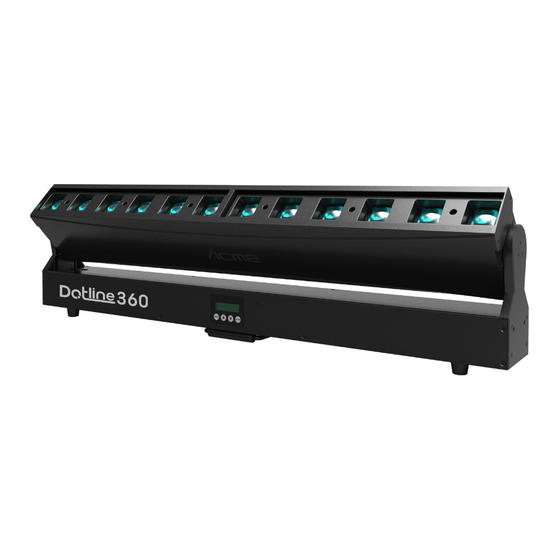
Summary of Contents for ACME Dotline 360
-
Page 2: Table Of Contents
CONTENTS 01/ Safety Instructions ....................2 02/ Technical Specifications ..................4 03/ Control Panel ......................5 04/ Fixture Installation ....................7 05/ How To Set The Unit ....................8 5.1 Main Functions ....................8 5.2 Home Position Adjustment ................. 19 06/ Control By Universal DMX Controller .............. -
Page 3: 01/ Safety Instructions
01/ Safety Instructions Please read the instruction carefully which includes important information about the installation, usage and maintenance. WARNING Please keep this User Guide for future consultation. If you sell the unit to another user, be sure that they also receive this instruction manual. Important: Damages caused by the disregard of this user manual are not subject to warranty. - Page 4 off the mains power immediately. DO NOT operate in a dirty or dusty environment. DO clean the fixture regularly. DO NOT touch any wire during operation as there might be a hazard of electric shock. Avoid entanglement of the power cord with other wires. ...
-
Page 5: 02/ Technical Specifications
02/ Technical Specifications Power Voltage 100-240V~ 50/60Hz Power Consumption 440W Light Source 12x30W RGBW LED Zoom Range 3.5°-38° 0-100% smooth dimming; outstanding strobe effect with variable Dimmer/Strobe speed Tilt Movement 220° DMX Channel 57/14/9+ Channels DMX512 Control Control Mode Art-Net Firmware Upgrade Firmware Upgrade via DMX link Display... -
Page 6: 03/ Control Panel
Photometric Diagram: 03/ Control Panel - 5 -... - Page 7 1. Display To show the various menus and the selected function MENU To enter into move backward or leave the menu UP To go backward to move up in the menu 2. Buttons DOWN To go forward to move down in the menu ENTER To perform the desired functions 3.
-
Page 8: 04/ Fixture Installation
04/ Fixture Installation DO install and operate by qualified operator. Fixture(s) should be installed in areas outside walking paths, seating areas, or away from areas were unauthorized personnel might reach the fixture by hand. NEVER stand directly below the fixture(s) when rigging, removing or servicing. -
Page 9: 05/ How To Set The Unit
05/ How To Set The Unit 5.1 Main Functions To access the control menus, press the [MENU] button. Navigate the menu structure, using the [ENTER], [ UP] and [ DOWN] buttons. To select a menu option or to confirm a selection, press the [ENTER] button. ... - Page 10 MENU SUBMENU OPTIONS Smooth Dimmer Speed Fast Disable Invert Tilt Enable Disable Tilt Feedback Enable Disable Bl. O. Tilt Moving Enable Silent Fan Mode Auto Disable Invert Pixel Order Enable Disable Artnet to DMX Enable Auto Test Tilt 0-255 Zoom 0-255 Dimmer 0-255...
- Page 11 MENU SUBMENU OPTIONS Reset Function Tilt Zoom Factory Setting DMX Setting Enter the control menu and select DMX Setting, press ENTER. Use the UP/DOWN button to select Art-Net Setup, DMX Address, Channel Mode, RDM Device ID, Mode 3 DMX Addr or Mode 3 ART Addr.
- Page 12 Channel Mode Select DMX Channel Mode, press ENTER. Use UP/DOWN button to select between 57 CH, 14 CH and 9+, confirm your selection with ENTER. To exit the menu, press MENU, or wait 30 seconds. RDM Device ID Select RDM Device ID, press ENTER. The RDM device ID is displayed.
- Page 13 Fixture Setting Enter the control menu and select Fixture Setting, press ENTER. Use the UP/DOWN button to select Light Mode, Dimmer Curve, Dimmer Speed, Invert Tilt, Tilt Feedback, Bl. O. Tilt Moving, Fan Mode, Invert Pixel Order or Artnet to DMX. Light Mode Select Light Mode, press ENTER.
- Page 14 Tilt Feedback Select Tilt Feedback, press ENTER. Use UP/DOWN button to select Disable (tilt feedback deactivated) or Enable (tilt feedback activated), confirm your selection with ENTER. To exit the menu, press MENU, or wait 30 seconds. Bl. O. Tilt Moving Select Bl.
- Page 15 Auto Test Select Auto Test, press ENTER. The device immediately performs an automatic self-test. To end the automatic self-test and exit the menu, press MENU, or wait 30 seconds. Manual Mode Select Manual Mode, press ENTER. Use UP/DOWN button to select the channel for which the manual test is to be performed, confirm your selection with ENTER.
- Page 16 Display Warning Select Display Warning, press ENTER. Use UP/DOWN button to select Disable or Enable, confirm your selection with ENTER. To exit the menu, press MENU, or wait 30 seconds. Language Select Language, press ENTER. Use UP/DOWN button to select English or Chinese, confirm your selection with ENTER.
- Page 17 Fan Speed Select Fan Speed, press ENTER. The fan speed is displayed. To exit the menu, press MENU, or wait 30 seconds. Firmware Version Select Firmware Version, press ENTER. The firmware version is displayed. To exit the menu, press MENU, or wait 30 seconds. Reset Function Enter the control menu and select Reset Function, press ENTER.
- Page 18 Zoom Select Zoom, press ENTER. Use UP/DOWN button to select No or Yes (the device will run built-in program to reset zoom to its home positions), confirm your selection with ENTER. To exit the menu, press MENU, or wait 30 seconds. Factory Setting Select Factory Setting, press ENTER.
- Page 19 RDM functions: Certain menus of the device and functions can be called up via the RDM protocol. The parameter IDs are implemented as follows for different commands: Command Command Command Parameter ID ‘Discovery’ ‘Set’ ‘Get’ DISC_UNIQUE_BRANCH √ DISC_MUTE √ DISC_UN_MUTE √...
-
Page 20: Home Position Adjustment
5.2 Home Position Adjustment To access the control menus, press the [MENU] button. To access the offset menus, long-press the [ENTER] button. Navigate the offset menus, using the [ENTER], [ UP] and [ DOWN] buttons. To select a menu option or to confirm a selection, press the [ENTER] button. ... -
Page 21: 06/ Control By Universal Dmx Controller
06/ Control By Universal DMX Controller 6.1 DMX512 Connection 1. At last unit, the DMX cable has to be terminated with a terminator. Solder a 120-ohm 1/4W resistor between pin 2(DMX-) and pin 3(DMX+) into a 3-pin XLR-plug and plug it in the DMX-output of the last unit. -
Page 22: Address Setting
6.2 Address Setting If you use a universal DMX controller to control the units, you have to set DMX address between 1 and 512 so that the units can receive DMX signal. Press the MENU button to access the control menus, select DMX Setting, press the ENTER button to confirm. - Page 23 57 Channels (Mode 1): CHANNEL VALUE FUNCTION Tilt 000-255 0°220° 000-255 Tilt Fine Tilt Speed 000-007 auto speed 008-247 slow to fast 248-255 auto speed Zoom 1 000-255 0%100% Zoom 2 000-255 0%100% Dimmer 000-255 0%100% 000-255 Dimmer Fine Strobe 000-031 Closed 032-063...
- Page 24 000-255 0%100% LED3 BLUE 000-255 0%100% LED3 WHITE 0%100% 000-255 LED 4RED 000-255 0%100% LED4 GREEN 0%100% 000-255 LED4 BLUE 0%100% 000-255 LED4 WHITE 0%100% 000-255 LED5 RED 0%100% 000-255 LED5 GREEN 000-255 0%100% LED5 BLUE 0%100% 000-255 LED5 WHITE 0%100% 000-255 LED6 RED...
- Page 25 000-255 0%100% LED9 RED 000-255 0%100% LED9 GREEN 0%100% 000-255 LED9 BLUE 000-255 0%100% LED9 WHITE 0%100% 000-255 LED10 RED 0%100% 000-255 LED10 GREEN 0%100% 000-255 LED10 BLUE 0%100% 000-255 LED10WHITE 000-255 0%100% LED11 RED 0%100% 000-255 LED11 GREEN 0%100% 000-255 LED11 BLUE 000-255...
- Page 26 14 Channels (Mode 2): CHANNEL VALUE FUNCTION Tilt 000-255 0°220° 000-255 Tilt Fine Zoom 000-255 0%100% Dimmer 0%100% 000-255 000-255 Dimmer Fine Strobe 000-031 Closed 032-063 Open 064-095 Strobe from fast to slow 096-127 Open 128-159 Pulse-effect in sequences 160-191 Open 192-223 Random strobe from slow to fast...
- Page 27 101-120 Reset All 121-140 Reset Tilt 141-160 Reset Zoom 161-180 Dimmer Speed: Smooth 181-200 Dimmer Speed: Fast 201-220 Invert Pixel Order: No 221-240 Invert Pixel Order: Yes 241-255 No Function 9+ Channels (Mode 3): CHANNEL VALUE FUNCTION Controlled by DMX Tilt 000-255 0°220°...
- Page 28 181-200 Dimmer Speed: Fast 201-220 Invert Pixel Order: No 221-240 Invert Pixel Order: Yes 241-255 No Function Controlled by Art-Net LED1 RED 0%100% 000-255 LED1 GREEN 000-255 0%100% LED1 BLUE 0%100% 000-255 LED1 WHITE 000-255 0%100% LED2 RED 000-255 0%100% LED2 GREEN 0%100% 000-255...
- Page 29 LED5 WHITE 0%100% 000-255 LED6 RED 000-255 0%100% LED6 GREEN 000-255 0%100% LED6 BLUE 0%100% 000-255 LED6 WHITE 000-255 0%100% LED7 RED 000-255 0%100% LED7 GREEN 000-255 0%100% LED7 BLUE 000-255 0%100% LED7 WHITE 000-255 0%100% LED8 RED 000-255 0%100% LED8 GREEN 000-255 0%100%...
- Page 30 LED11 GREEN 0%100% 000-255 LED11 BLUE 000-255 0%100% LED11 WHITE 000-255 0%100% LED12 RED 0%100% 000-255 LED12 GREEN 000-255 0%100% LED12 BLUE 000-255 0%100% LED12 WHITE 000-255 0%100% - 29 -...
-
Page 31: 07/ Error Information
07/ Error Information Error codes are shown continuously in the display when the fixture fails and they will not disappear until the fixture is repaired. CPU-B/C/D/E/F Error Check whether the 485 (DATA) leads on the PCB board are installed in place or disconnected. - Page 32 Zoom 1/2 Reset Error Check whether the position of the zoom where the magnet is installed falls off or is damaged. Check whether there are obstacles in the zoom operating range. Check whether the Hall element on the zoom is damaged. Check whether the lead connecting the Hall element on the zoom and the PCB board is in poor contact or disconnected.
-
Page 33: 08/ Troubleshooting
08/ Troubleshooting Following are a few common problems that may occur during operation. Here are some suggestions for troubleshooting: A. The unit does not work, no light and the fan does not work Check the connected power and main fuse. ... - Page 34 Declaration of Conformity We declare that our products (lighting equipments) comply with the following specification and bears CE mark in accordance with the provision of the Electromagnetic Compatibility (EMC) Directive 2014/30/EU. EN 55032: 2015+A1: 2020; EN 55035: 2017+A11: 2020; EN IEC 61000-3-2: 2019+A1: 2021; EN 61000-3-3: 2013+A1: 2019+A2: 2021.
Need help?
Do you have a question about the Dotline 360 and is the answer not in the manual?
Questions and answers