Table of Contents
Advertisement
Quick Links
Advertisement
Table of Contents

Related Manuals for ACME BLINDER LINE 10 IP


Summary of Contents for ACME BLINDER LINE 10 IP
-
Page 2: Table Of Contents
CONTENTS 01/ Safety Instructions ....................2 02/ Technical Specifications ..................6 03/ Control Panel ......................8 04/ Fixture Installation ....................9 4.1 Stand the Fixture on the Floor ..............10 4.2 Hanging the Fixture ..................12 4.3 Splicing the Fixtures ..................14 05/ How To Set The Unit .................... -
Page 3: 01/ Safety Instructions
01/ Safety Instructions Please read the instruction carefully which includes important information about the installation, usage and maintenance. WARNING Please keep this User Guide for future consultation. If you sell the unit to another user, be sure that they also receive this instruction manual. Important: Damages caused by the disregard of this user manual are not subject to warranty. - Page 4 off the mains power immediately. DO NOT operate in a dirty or dusty environment. DO clean the fixture regularly. DO NOT touch any wire during operation as there might be a hazard of electric shock. Avoid entanglement of the power cord with other wires. ...
- Page 5 01/ Consignes de sécurité Veuillez lire attentivement les instructions qui contiennent des informations importantes sur l'installation, l'utilisation et l'entretien. ATTENTION Veuillez conserver ce guide de l'utilisateur pour une consultation future. Si vous vendez l'appareil à un autre utilisateur, assurez-vous qu'il reçoive également ce manuel d'instructions.
- Page 6 Assurez-vous que le cordon d'alimentation n'est pas pincé ou endommagé; remplacez-le immédiatement s'il est endommagé. La température de surface de l'unité peut atteindre 70℃. NE PAS toucher les capots à mains nues pendant son fonctionnement. Évitez que des liquides inflammables, de l'eau ou du métal ne pénètrent dans l'appareil. Si ...
-
Page 7: 02/ Technical Specifications
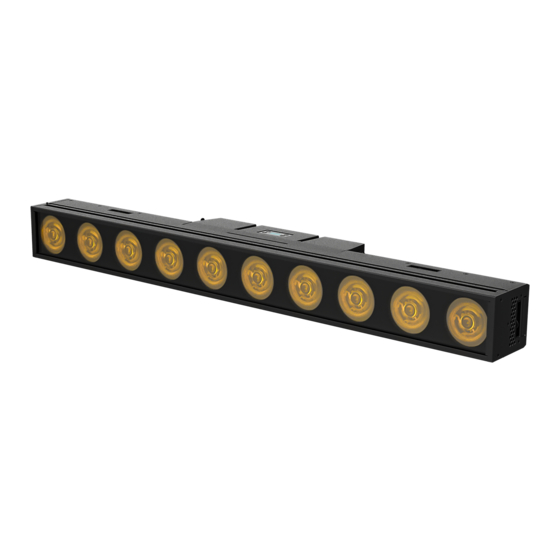
02/ Technical Specifications Power Voltage 100-240V~ 50/60Hz Power Consumption 690W Light Source TOC-YF-V2-RGBWA150x10pcs 23°/38°/54° (W) Beam Angle 25°/41°/55° (RGBA) 47°/97°/127° (W) Field Angle 49°/100°/128° (RGBA) 0-100% smooth dimming; outstanding strobe effect with variable Dimmer/Strobe speed DMX Channel 14/55 Channels DMX512 Control Control Mode Art-Net... - Page 8 IP66 protection rating, which can be used outdoors all the year round Dimensions 1000x103.3x160.3mm 39.4"x4.1"x6.3"in Weight 14.7kgs 32.4lbs Photometric Diagram (Beam Angle): Photometric Diagram (Field Angle): - 7 -...
-
Page 9: 03/ Control Panel
03/ Control Panel 1. Display To show the various menus and the selected function MENU To enter into move backward or leave the menu UP To go backward to move up in the menu 2. Buttons DOWN To go forward to move down in the menu ENTER To perform the desired functions 3. -
Page 10: 04/ Fixture Installation
04/ Fixture Installation DO install and operate by qualified operator. Fixture(s) should be installed in areas outside walking paths, seating areas, or away from areas were unauthorized personnel might reach the fixture by hand. NEVER stand directly below the fixture(s) when rigging, removing or servicing. -
Page 11: Stand The Fixture On The Floor
4.1 Stand the Fixture on the Floor Floor: Two floor brackets (sold separately): - 10 -... - Page 12 Vertical Stand: Mounted to floor stand (sold separately): Note: Fixture can only stand vertically in a single unit. No other fixtures can be spliced. A. Press the button: automatically the slide comes out completely. B. Place the fixture nicely against the floor stand in line so that the slide fits nicely into the floor stand.
-
Page 13: Hanging The Fixture
4.2 Hanging the Fixture Horizontal: Utilizing two omega brackets (supplied) and clamps (by others): Note: Only a maximum of 6 fixtures can be spliced vertically when hanging fixtures horizontally. - 12 -... - Page 14 Vertical: Using one omega bracket (sold separately) with clamp (by others): Note: Only a maximum of 3 fixtures can be spliced when hanging fixtures vertically. A. Press the button: automatically the slide comes out completely. B. Place the omega bracket with clamp nicely against the fixture in line so that the slide fits nicely into the omega bracket.
-
Page 15: Splicing The Fixtures
4.3 Splicing the Fixtures Splicing fixtures horizontally: A. Press the button: automatically the slide comes out completely. B. Place both fixtures nicely against each other in line so that the slide fits nicely into the other fixture. - 14 -... - Page 16 C. Insert the hex wrench into the hexagonal slot and tighten it clockwise to release and secure the locking mechanism inside the fixture with the other fixture. D. Finally, tighten the four rivet screws to secure both fixtures. If you need to align more fixtures, repeat the steps above. To detach the fixtures, simply reverse the steps mentioned above.
- Page 17 Splicing fixtures vertically: A. Place both fixtures nicely against each other in line B. Insert the hex wrench into the hexagonal slots and tighten them clockwise to release and secure the locking mechanisms inside the fixture with the other fixture. If you need to align more fixtures, repeat the steps above.
-
Page 18: 05/ How To Set The Unit
05/ How To Set The Unit 5.1 Main Functions To access the control menus, press the [MENU] button. Navigate the menu structure, using the [ENTER], [ UP] and [ DOWN] buttons. To select a menu option or to confirm a selection, press the [ENTER] button. ... - Page 19 MENU SUBMENU OPTIONS Linear Square Law Dimmer Curve Inv SQ Law S Curve Smooth Dimmer Speed Fast Tungsten 125-255 Green 125-255 Blue 125-255 Red 1 125-255 Green 1 125-255 White Balance Blue 1 125-255 …… …… Red 10 125-255 Green 10 125-255 Blue 10 125-255...
- Page 20 MENU SUBMENU OPTIONS English Language Chinese Auto Test Mode 1 Mode 2 Clear No/Yes Clear No/Yes Frost 0-255 Frost 0-255 Strobe 0-255 Strobe 0-255 Dimmer 0-255 Dimmer 0-255 White 0-255 White 1 0-255 0-255 Red 1 0-255 Green 0-255 Green 1 0-255 Manual Test Blue...
- Page 21 DMX Settings Enter the control menu and select DMX Settings, press ENTER. Use the UP/DOWN button to select DMX Address, DMX CH Mode, No DMX Status, View DMX Value, Connect Option, Network, Art-Net Settings, sACN Settings or Network to DMX. DMX Address Select DMX Address, press ENTER.
- Page 22 View DMX Value Select View DMX Value, press ENTER. Use UP/DOWN button to select the desired DMX channel, for which the value is to be displayed. To exit the menu, press MENU, or wait 30 seconds. Connect Option Select Connect Option, press ENTER. Use UP/DOWN button to select Auto, DMX, Art-Net or sACN, confirm your selection with ENTER.
- Page 23 Fixture Settings Enter the control menu and select Fixture Settings, press ENTER. Use the UP/DOWN button to select Dimmer Curve, Dimmer Speed, White Balance, LED Refresh Rate, Invert Pixel or Wireless. Dimmer Curve Select Dimmer Curve, press ENTER. Use UP/DOWN button to select Linear, Square Law, Inv SQ Law or S Curve, confirm your selection with ENTER.
- Page 24 LED Refresh Rate Select LED Refresh Rate, press ENTER. Use UP/DOWN button to select 900Hz, 1000Hz, 1100Hz, 1200Hz, 1300Hz, 1400Hz, 1500Hz, 2500Hz, 4000Hz, 5000Hz, 6000Hz, 10KHz, 15KHz, 20KHz or 25KHz, confirm your selection with ENTER. To exit the menu, press MENU, or wait 30 seconds. Invert Pixel Select Invert Pixel, press ENTER.
- Page 25 Temperature Unit Select Temperature Unit, press ENTER. Use UP/DOWN button to select °C or °F, confirm your selection with ENTER. To exit the menu, press MENU, or wait 30 seconds. Language Select Language, press ENTER. Use UP/DOWN button to select English or Chinese, confirm your selection with ENTER.
- Page 26 Information Enter the control menu and select Information, press ENTER. Use the UP/DOWN button to select Fixture Use Hour, LED Use Hour, Temperature, Fan State, Firmware Version, BT WIFI Version, RDM UID or Error Logs. Fixture Use Hour Select Fixture Use Hour, press ENTER. The operating hours is displayed.
- Page 27 Firmware Version Select Firmware Version, press ENTER. The firmware version is displayed. To exit the menu, press MENU, or wait 30 seconds. BT WIFI Version Select BT WIFI Version, press ENTER. The version of the wireless module is displayed. To exit the menu, press MENU, or wait 30 seconds. RDM UID Select RDM UID, press ENTER.
- Page 28 RDM functions: Certain menus of the device and functions can be called up via the RDM protocol. The parameter IDs are implemented as follows for different commands: Command Command Command Parameter ID ‘Discovery’ ‘Set’ ‘Get’ DISC_UNIQUE_BRANCH √ DISC_MUTE √ DISC_UN_MUTE √...
-
Page 29: Home Position Adjustment
5.2 Home Position Adjustment To access the control menus, press the [MENU] button. To access the offset menus, long-press the [ENTER] button. Navigate the offset menus, using the [ENTER], [ UP] and [ DOWN] buttons. To select a menu option or to confirm a selection, press the [ENTER] button. ... - Page 30 Frequency Select Frequency, press ENTER. Use UP/DOWN button to select a value, confirm your selection with ENTER. To exit the offset menu, press MENU, or wait 30 seconds. Frequency VALUES 900Hz 772~1027 1000Hz 872~1127 1100Hz 972~1227 1200Hz 1072~1327 1300Hz 1172~1427 1400Hz 1272~1527 1500Hz...
- Page 31 Green Select Green, press ENTER. Use UP/DOWN button to select a value between 0 and 255, confirm your selection with ENTER. To exit the offset menu, press MENU, or wait 30 seconds. Blue Select Blue, press ENTER. Use UP/DOWN button to select a value between 0 and 255, confirm your selection with ENTER.
- Page 32 Green 1 Select Green 1, press ENTER. Use UP/DOWN button to select a value between 0 and 255, confirm your selection with ENTER. To exit the offset menu, press MENU, or wait 30 seconds. Blue 1 Select Blue 1, press ENTER. Use UP/DOWN button to select a value between 0 and 255, confirm your selection with ENTER.
- Page 33 Green 10 Select Green 10, press ENTER. Use UP/DOWN button to select a value between 0 and 255, confirm your selection with ENTER. To exit the offset menu, press MENU, or wait 30 seconds. Blue 10 Select Blue 10, press ENTER. Use UP/DOWN button to select a value between 0 and 255, confirm your selection with ENTER.
-
Page 34: 06/ Control By Universal Dmx Controller
06/ Control By Universal DMX Controller 6.1 DMX512 Connection 1. At last unit, the DMX cable has to be terminated with a terminator. Solder a 120-ohm 1/4W resistor between pin 2(DMX-) and pin 3(DMX+) into a 3-pin XLR-plug and plug it in the DMX-output of the last unit. -
Page 35: Address Setting
6.2 Address Setting If you use a universal DMX controller to control the units, you have to set DMX address between 1 and 512 so that the units can receive DMX signal. Press the MENU button to access the control menus, select DMX Settings, press the ENTER button to confirm. - Page 36 CHANNEL VALUE FUNCTION 14ch 55ch SPECIAL FUNCTION 000-005 Null 006-007 Wireless: On 008-009 Wireless: Off 010-029 Null 030-039 Dimmer Curve: Linear 040-049 Dimmer Curve: Square Law 050-059 Dimmer Curve: Inv SQ Law 060-069 Dimmer Curve: S Curve 070-099 Null 100-109 Led Frequency Setting Enable 110-119 Led Frequency Setting Disable...
- Page 37 140-181 Fast Open Slow Close from Slow to Fast 182-189 Open 190-231 Slow Open Fast Close from Slow to Fast 232-239 Open 240-247 Random Strobe from Slow to Fast 248-255 Open DIMMER 000-255 0%100% 000-255 DIMMER FINE WHITE 000-255 0%100% 000-255 0%100% GREEN...
- Page 38 113-117 5500K 118-121 5400K 122-126 5300K 127-130 5200K 131-135 5100K 136-139 5000K 140-144 4900K 145-148 4800K 149-153 4700K 154-157 4600K 158-162 4500K 163-166 4400K 167-171 4300K 172-175 4200K 176-180 4100K 181-184 4000K 185-189 3900K 190-193 3800K 194-198 3700K 199-202 3600K 203-207 3500K 208-211...
- Page 39 108-114 LEE 202 – Half CT Blue 115-121 LEE 117 – Steel Blue 122-128 LEE 353 – Lighter Blue 129-135 LEE 118 – Light Blue 136-142 LEE 116 – Medium Blue Green 143-149 LEE 124 – Dark Green 150-156 LEE 139 – Primary Green 157-163 LEE 089 –...
- Page 40 BLUE 1 0%100% 000-255 AMBER 1 000-255 0%100% WHITE 2 000-255 0%100% RED 2 0%100% 000-255 GREEN 2 000-255 0%100% BLUE 2 000-255 0%100% AMBER 2 000-255 0%100% WHITE 3 000-255 0%100% RED 3 000-255 0%100% GREEN 3 000-255 0%100% BLUE 3 000-255 0%100%...
- Page 41 WHITE 6 0%100% 000-255 RED 6 000-255 0%100% GREEN 6 000-255 0%100% BLUE 6 0%100% 000-255 AMBER 6 000-255 0%100% WHITE 7 000-255 0%100% RED 7 000-255 0%100% GREEN 7 000-255 0%100% BLUE 7 000-255 0%100% AMBER 7 000-255 0%100% WHITE 8 000-255 0%100%...
-
Page 42: 07/ Error Information
GREEN 10 0%100% 000-255 BLUE 10 000-255 0%100% AMBER 10 000-255 0%100% 07/ Error Information Error codes are shown continuously in the display when the fixture fails and they will not disappear until the fixture is repaired. CPU-B/C/D Error Check whether the 485 (DATA) leads on the PCB board are installed in place or disconnected. - Page 43 Base Fan Start Err Check whether the fan is not running. Check whether the fan leads are installed in place or disconnected. Check whether the fan is damaged. Check whether there are obstacles in the fan operating range. Base Fan Too Slow Check whether the fan is out of order.
-
Page 44: 08/ Troubleshooting
08/ Troubleshooting Following are a few common problems that may occur during operation. Here are some suggestions for troubleshooting: A. The unit does not work, no light and the fan does not work Check the connected power. Measure the voltage. ...
Need help?
Do you have a question about the BLINDER LINE 10 IP and is the answer not in the manual?
Questions and answers