Table of Contents
Advertisement
Quick Links
Advertisement
Table of Contents

Related Manuals for ACME Neozone 5


Summary of Contents for ACME Neozone 5
-
Page 2: Table Of Contents
CONTENTS 01/ Safety Information ....................2 02/ Technical Specifications ..................6 03/ Overview ........................8 04/ Connecting Power and Data ................9 4.1 Connecting Power ................... 9 4.2 Connecting Data.................... 10 05/ Fixture Installation ....................11 06/ Operation ....................... 13 6.1 Control Menu .................... -
Page 3: 01/ Safety Information
01/ Safety Information Please read the instruction carefully which includes important information about the installation, usage and maintenance. WARNING Please keep this User Manual for future consultation. If you sell the unit to another user, be sure that they also receive this instruction manual. Important: Damages caused by the disregard of this user manual are not subject to warranty. - Page 4 off the mains power immediately. DO NOT operate in a dirty or dusty environment. DO clean the fixture regularly. DO NOT touch any wire during operation as there might be a hazard of electric shock. Avoid entanglement of the power cord with other wires. ...
- Page 5 01/ Consignes de sécurité Veuillez lire attentivement les instructions qui contiennent des informations importantes sur l'installation, l'utilisation et l'entretien. ATTENTION Veuillez conserver ce guide de l'utilisateur pour une consultation future. Si vous vendez l'appareil à un autre utilisateur, assurez-vous qu'il reçoive également ce manuel d'instructions.
- Page 6 pour éviter tout risque d'incendie. Assurez-vous que le cordon d'alimentation n'est pas pincé ou endommagé; remplacez-le immédiatement s'il est endommagé. La température de surface de l'unité peut atteindre 75℃. NE PAS toucher les capots à mains nues pendant son fonctionnement. Évitez que des liquides inflammables, de l'eau ou du métal ne pénètrent dans l'appareil.
-
Page 7: 02/ Technical Specifications
02/ Technical Specifications AC Power 100-240Vac; 50/60Hz Max. Power 960W Consumption Light Source 19x40W RGBW LED Beam Angle 3.5°-28.5° Field Angle 5°-50° 540° Tilt 220° Movement 16 bit movement resolution Automatic pan/tilt repositioning DMX Channels 17/21/86/10+ DMX512 Control and Protocols Programming Art-Net sACN... - Page 8 2 x fixed clamps for 50mm truss (version with fixed foldable clamps) 389.6x223x496.4mm Dimensions 15.3"x8.8"x19.5" (version with omega bracket holes) 389.6x223x530.9mm Dimensions 15.3"x8.8"x20.9" (version with fixed foldable clamps) 20 kg Weight 44.1 lbs (version with omega bracket holes) 21.3 kg Weight 47 lbs (version with fixed foldable clamps)
-
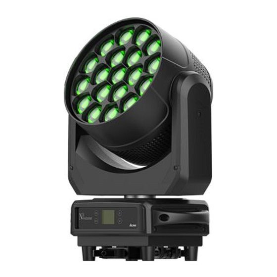
Page 9: 03/ Overview
03/ Overview 1. Display To show the various menus and the selected function MENU To enter into move backward or leave the menu UP To go backward to move up in the menu 2. Buttons DOWN To go forward to move down in the menu ENTER To perform the desired functions 3. -
Page 10: 04/ Connecting Power And Data
04/ Connecting Power and Data 4.1 Connecting Power This fixture can operate on any 100-240Vac; 50/60Hz AC mains power supply. The maximum power consumption is 960W. The fixture must be grounded/earthed and able to be isolated from AC power. The AC power supply must incorporate a fuse or circuit breaker for fault protection. -
Page 11: Connecting Data
4.2 Connecting Data The fixture is equipped with 3-pin (or 5-pin) XLR sockets for DMX input and output. Use a high-quality DMX cable designed for RS-485 and 3-pin (or 5-pin) XLR-plugs and connectors in order to connect the controller with the fixture or one fixture with another. Building a serial DMX chain: Connect the DMX data output from the controller to the fixture’s data input socket. -
Page 12: 05/ Fixture Installation
05/ Fixture Installation DO install and operate by qualified operator. Fixture(s) should be installed in areas outside walking paths, seating areas, or away from areas were unauthorized personnel might reach the fixture by hand. NEVER stand directly below the fixture(s) when rigging, removing or servicing. - Page 13 Steps for installing omega brackets to the fixture: - 12 -...
-
Page 14: 06/ Operation
06/ Operation 6.1 Control Menu To access the control menus, press the [MENU] button. Navigate the menu structure, using the [ENTER], [ UP] and [ DOWN] buttons. To select a menu option or to confirm a selection, press the [ENTER] button. ... - Page 15 MAIN MENU SUBMENU CHOICES/VALUES Network to DMX Pan Invert Tilt Invert P/T Feedback Fast Dimmer Speed Smooth Linear Square Law Dimmer Curve Inv SQ Law S Curve 125-255 Green 125-255 Blue 125-255 Fixture Settings Red 1 125-255 Green 1 125-255 White Balance Blue 1 125-255...
- Page 16 MAIN MENU SUBMENU CHOICES/VALUES English Language Chinese Single Auto Test Cycle Mode 1 Mode 2 Clear No/Yes Clear No/Yes 0-255 0-255 Tilt 0-255 Tilt 0-255 Zoom 0-255 Zoom 0-255 Strobe 0-255 Dimmer 0-255 Dimmer 0-255 Strobe 0-255 Fixture Test Red 1 0-255 0-255 Manual Test...
- Page 17 MAIN MENU SUBMENU CHOICES/VALUES Pan/Tilt Reset Reset Function Effect Reset All Reset Special Function Factory Settings DMX Settings Enter the control menu and select DMX Settings, press ENTER. Use the UP/DOWN button to select DMX Address, DMX Channel Mode, No DMX Status, View DMX Value, Connect Option, Network, Art-Net Settings, sACN Settings or Network to DMX.
- Page 18 No DMX Status Select No DMX Status, press ENTER. Use UP/DOWN button to select one of the following status: Blackout (Fixture blacks out if DMX signal stops) Hold (The device continues to operate in the current mode with the last active DMX values until the signal returns) Manual (The device accepts the DMX value stored in the ‘Manual Test’...
- Page 19 sACN Settings Select sACN Settings, press ENTER. Use UP/DOWN button to select Universe or Priority, confirm your selection with ENTER. To exit the menu, press MENU, or wait 30 seconds. Network to DMX Select Network to DMX, press ENTER. Use UP/DOWN button to select No or Yes, confirm your selection with ENTER.
- Page 20 P/T Feedback Select P/T Feedback, press ENTER. Use UP/DOWN button to select No (pan/tilt feedback deactivated) or Yes (pan/tilt feedback activated), confirm your selection with ENTER. To exit the menu, press MENU, or wait 30 seconds. Dimmer Speed Select Dimmer Speed, press ENTER. Use UP/DOWN button to select Fast or Smooth, confirm your selection with ENTER.
- Page 21 Color Calibration Select Color Calibration, press ENTER. Use UP/DOWN button to select Off or On, confirm your selection with ENTER. To exit the menu, press MENU, or wait 30 seconds. Calibration Mode Select Calibration Mode, press ENTER. Use UP/DOWN button to select Hi CRI or Hi Output, confirm your selection with ENTER.
- Page 22 Display Settings Enter the control menu and select Display Settings, press ENTER. Use the UP/DOWN button to select Display Invert, Backlight Intensity, Temperature Unit or Language. Display Invert Select Display Invert, press ENTER. Use UP/DOWN button to select No (display normal) or Yes (display inverted), confirm your selection with ENTER.
- Page 23 Fixture Test Enter the control menu and select Fixture Test, press ENTER. Use the UP/DOWN button to select Auto Test or Manual Test. Auto Test Select Auto Test, press ENTER. Use UP/DOWN button to select Single (the device immediately performs a single automatic self-test) or Cycle (the device immediately performs a cyclic automatic self-test), confirm your selection with ENTER.
- Page 24 LED Use Hour Select LED Use Hour, press ENTER. Use UP/DOWN button to select Total LED Hour (total time) or LED On Hour (current switch-on time), confirm your selection with ENTER. The total time or current switch-on time is displayed. Use UP/DOWN button to select LED Hours Reset, confirm your selection with ENTER.
- Page 25 Error Logs Select Error Logs, press ENTER. Use UP/DOWN button to select Fixture Errors, confirm your selection with ENTER. The error list is displayed. Use UP/DOWN button to select Reset Error Log, confirm your selection with ENTER. If you wish to reset the relevant error logs, select Yes. If you do not wish to reset anything, select No.
- Page 26 All Reset Select All Reset, press ENTER. Use UP/DOWN button to select No or Yes (the device will run built-in program to reset all to their home positions), confirm your selection with ENTER. To exit the menu, press MENU, or wait 30 seconds. Special Function Enter the control menu and select Special Function, press ENTER.
- Page 27 RDM functions: Certain menus of the device and functions can be called up via the RDM protocol. The parameter IDs are implemented as follows for different commands: Command Command Command Parameter ID ‘Discovery’ ‘Set’ ‘Get’ DISC_UNIQUE_BRANCH √ DISC_MUTE √ DISC_UN_MUTE √...
-
Page 28: Home Position Adjustment
6.2 Home Position Adjustment To access the control menus, press the [MENU] button. To access the offset menus, long-press the [ENTER] button. Navigate the offset menus, using the [ENTER], [ UP] and [ DOWN] buttons. To select a menu option or to confirm a selection, press the [ENTER] button. ... - Page 29 Tilt Select Tilt, press ENTER. Use UP/DOWN button to select a value between -128 and 127, confirm your selection with ENTER. To exit the offset menu, press MENU, or wait 30 seconds. Zoom Select Zoom, press ENTER. Use UP/DOWN button to select a value between -128 and 127, confirm your selection with ENTER.
- Page 30 …… Red 19 Select Red 19, press ENTER. Use UP/DOWN button to select a value between 0 and 1000, confirm your selection with ENTER. To exit the offset menu, press MENU, or wait 30 seconds. Green 19 Select Green 19, press ENTER. Use UP/DOWN button to select a value between 0 and 1000, confirm your selection with ENTER.
-
Page 31: 07/ Configuring The Device For Dmx Control
07/ Configuring the Device for DMX Control 7.1 Address Setting All fixtures should be given a DMX starting address when operating with a DMX controller, in order to ensure that the correct fixture responds to the correct control signal. Incorrect settings will result in unpredictable responses from the lighting controller. -
Page 32: Dmx Protocol
7.2 DMX Protocol CHANNEL VALUE FUNCTION 10+ch 17ch 21ch 86ch 10+ch (Controlled by DMX) 000-255 0°540° 000-255 PAN FINE TILT 000-255 0°220° 000-255 TILT FINE PAN/TILT SPEED 000-255 Fast to Slow ZOOM NarrowWide 000-255 DIMMER 000-255 0%100% 000-255 DIMMER FINE STROBE 000-007 Close... - Page 33 110-119 Led Frequency Setting Disable 120-129 Null 130-139 Null 140-149 Pan/Tilt Reset 150-159 Effect Reset 160-169 Color Calibration: On 170-179 Color Calibration: Off 180-189 Calibration Mode: High CRI 190-199 Calibration Mode: High Output 200-209 All Reset 210-219 Dimmer Speed Fast 220-229 Dimmer Speed Smooth 230-239...
- Page 34 BLUE 3 0%100% 000-255 WHITE 3 000-255 0%100% RED 4 000-255 0%100% GREEN 4 0%100% 000-255 BLUE 4 000-255 0%100% WHITE 4 000-255 0%100% RED 5 000-255 0%100% GREEN 5 000-255 0%100% BLUE 5 000-255 0%100% WHITE 5 000-255 0%100% RED 6 000-255 0%100%...
- Page 35 RED 9 0%100% 000-255 GREEN 9 000-255 0%100% BLUE 9 000-255 0%100% WHITE 9 0%100% 000-255 RED 10 000-255 0%100% GREEN 10 000-255 0%100% BLUE 10 000-255 0%100% WHITE 10 000-255 0%100% RED 11 000-255 0%100% GREEN 11 000-255 0%100% BLUE 11 000-255 0%100%...
- Page 36 BLUE 14 0%100% 000-255 WHITE 14 000-255 0%100% RED 15 000-255 0%100% GREEN 15 0%100% 000-255 BLUE 15 000-255 0%100% WHITE 15 000-255 0%100% RED 16 000-255 0%100% GREEN 16 000-255 0%100% BLUE 16 000-255 0%100% WHITE 16 000-255 0%100% RED 17 000-255 0%100%...
- Page 37 CTO (8000K-2500K) Null 001-004 8000K 005-009 7900K 010-013 7800K 014-018 7700K 019-022 7600K 023-027 7500K 028-031 7400K 032-036 7300K 037-040 7200K 041-045 7100K 046-049 7000K 050-054 6900K 055-058 6800K 059-063 6700K 064-067 6600K 068-072 6500K 073-076 6400K 077-081 6300K 082-085 6200K 086-090 6100K...
- Page 38 208-211 3400K 212-216 3300K 217-220 3200K 221-225 3100K 226-229 3000K 230-234 2900K 235-238 2800K 239-243 2700K 244-247 2600K 248-255 2500K COLOR MACRO 000-007 Null 008-011 Color 1 012-015 Color 2 016-019 Color 3 020-023 Color 4 024-027 Color 5 028-031 Color 6 032-035 Color 7...
- Page 39 206-215 RedBlue 216-225 RedWhite 226-235 GreenBlue 236-245 GreenWhite 246-255 BlueWhite PIXEL (See “Pixel of 16 CH” in detail) Null Open 002-245 Pattern1-244 Built-in Mode1 Built-in Mode2 Built-in Mode3 Random One Pixel Random Two Pixels 251-255 Open PIXEL ROTATION 000-031 Null 032-091 Rotate CW Fast to Slow 092-101...
- Page 40 Pixel of 16 CH: - 39 -...
- Page 41 - 40 -...
- Page 42 - 41 -...
-
Page 43: 08/ Error Information
08/ Error Information Error codes are shown continuously in the display when the fixture fails and they will not disappear until the fixture is repaired. CPU-B/C/D/E/F Error Check whether the 485 (DATA) leads on the PCB board are installed in place or disconnected. - Page 44 Tilt Reset Error Check whether the position of the tilt where the magnet is installed falls off or is damaged. Check whether there are obstacles in the tilt operating range. Check whether the Hall element on the tilt is damaged. Check whether the lead connecting the Hall element on the tilt and the PCB board is in poor contact or disconnected.
- Page 45 LED Temp. 1/2/3 Error Check whether the temperature detecting board is normal. Check whether the components of the temperature detecting board are damaged. Check whether the lead on the temperature detecting board is installed in place or disconnected. LED Timeout Use LED Too Hot Off When the fixture temperature reaches 85℃, it will automatically turn off to protect the fixture.
- Page 46 Head Fan 1/2 Start Err Check whether the fan is not running. Check whether the fan leads are installed in place or disconnected. Check whether the fan is damaged. Check whether there are obstacles in the fan operating range. Head Fan 1/2 Stop Err Check whether the fan circuit on the motherboard breaks down.
- Page 47 Position of cooling fans: Cooling Fans Part Number Position Head Fan 1 3014001310 DC 24V 3.8W Head - C Head Fan 2 Base Fan 1 3014001330 DC 24V Base - A Base Fan 2 - 46 -...
-
Page 48: 09/ Troubleshooting
09/ Troubleshooting Problem Potential cause(s) Remedies Confirm that the power is switched No power to the fixture. Fixture does not respond on and cables are plugged in. or appears to be off. No output from PSU. Replace the PSU. Fixture suddenly turned Check the power supply, switches Power was turned off. -
Page 49: 10/ Fixture Cleaning
10/ Fixture Cleaning Regular cleaning is very important for fixture life and performance. Buildup of dust, dirt, smoke particles, fog fluid residues, etc. degrades the fixture’s light output and cooling ability. Cleaning schedules for lighting fixtures vary greatly depending on the operating environment. It is therefore impossible to specify precise cleaning intervals for the fixture. -
Page 50: 11/ Approvals And Certifications
11/ Approvals and Certifications This product has been tested and found to comply with the following standards: - 2014/30/EU - Electromagnetic Compatibility (EMC) - 2014/35/EU - Low Voltage Directive (LVD) - cETLus Approved (Control #5000057) The information in this document is subject to change without notice. For the latest information, visit www.acmelighting.com.
Need help?
Do you have a question about the Neozone 5 and is the answer not in the manual?
Questions and answers