
Subscribe to Our Youtube Channel
Related Manuals for Lanner NCA-6530


Summary of Contents for Lanner NCA-6530
- Page 1 Network Appliance Platform NCA-6530 User Manual Version: 1.0 Date of Release:2023-06-14...
- Page 2 - assumed to be qualified in the servicing of computer equipment, such as professional system integrators, or service personnel and technicians. The latest version of this document can be found on Lanner’s official website, available either through the product page or through the Lanner Download Center page with a login account and password.
- Page 3 NCA-6530 User Manual Taiwan Corporate Headquarters China Lanner Electronics Inc. Beijing L&S Lancom Platform Tech. Co., Ltd. 7F, No.173, Sec.2, Datong Rd. Guodong LOFT 9 Layer No. 9 Huinan Road, Xizhi District, New Taipei City 22184, Huilongguan Town, Changping District, Beijing...
- Page 4 NCA-6530 User Manual Intel® and Intel® Celeron® are trademarks of Intel Corporation or its subsidiaries in the U.S. and/or other countries. Microsoft Windows and MS-DOS are registered trademarks of Microsoft Corp. All other product names or trademarks are properties of their respective owners.
- Page 5 NCA-6530 User Manual Follow these guidelines to ensure general safety: Keep the chassis area clear and dust-free during and after installation. Do not wear loose clothing or jewelry that could get caught in the chassis. Fasten your tie or scarf and roll up your sleeves.
- Page 6 The installation of this product must be performed by trained specialists; otherwise, a non-specialist might create the risk of the system’s falling to the ground or other damages. Lanner Electronics Inc. shall not be held liable for any losses resulting from insufficient strength for supporting the system or use of inappropriate installation components.
- Page 7 NCA-6530 User Manual Connect the grounding cable to the ground. The protection device for the DC power source must provide 40A current. This protection device must be connected to the power source before DC power. Branchez le câble de mise à la terre à la terre.
- Page 8 NCA-6530 User Manual Table of Contents Chapter 1: Product Overview Package Content ......................... 10 Ordering Information ......................... 10 Optional Accessories ........................10 System Specifications ......................... 11 Front Panel ..........................12 Rear Panel ........................... 14 Motherboard Layout ........................16 Internal Jumper & Connectors ....................17 Installing the CPU ........................
- Page 9 NCA-6530 User Manual BMC Main Features ........................61 BMC Firmware Functional Description ..................62 IPMI Commands Support List ..................... 64 Using BMC Web UI ........................66 Web UI Layout Introduction ....................... 69 Help............................. 71 Main Page ........................... 73 Platform Setup ..........................94 Server Mgmt Setup ........................
-
Page 10: Chapter 1: Product Overview
NCA-6530 User Manual CHAPTER 1: PRODUCT OVERVIEW Thank you for choosing NCA-6530. The NCA-6530, a high-performance 2U rackmount network appliance, is powered by Intel® Xeon® Processor Scalable Family (Codenamed Sapphire Rapids-SP) and supports up to 8x NIC slots, Max. 1536GB system memory, 6x hot-swappable fans, 1600W/2000W redundant PSUs, Intel®... - Page 11 NCA-6530 User Manual Form Factor 2U 19“ Rackmount Processor Options Intel® Xeon® Processor Scalable Family (Sapphire Rapids-SP) CPU Socket 2x LGA4677 Platform Chipset Intel® C741 Security Acceleration Intel® QuickAssist Technology BIOS AMI SPI Flash BIOS Technology DDR5 4800 MHz R-DIMM System Memory Max.
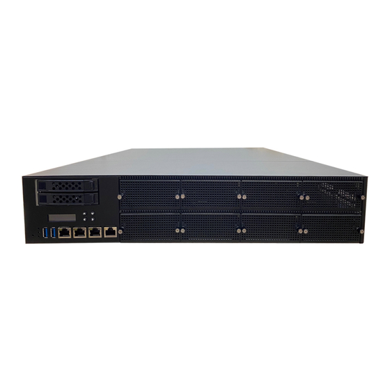
- Page 12 NCA-6530 User Manual NCA-6530A / NCA-6530C F7 F8 Description HDD/SSD Bays 2x 2.5” HDD/SSD Trays 16x2 Character LCD, 4x Keypads Reset Button 1x Software Reset Button System Power LED Indicators System Status HDD Activity USB Port 2x USB 3.0 Ports...
- Page 13 NCA-6530 User Manual NCA-6530B / NCA-6530D F7 F8 Description HDD/SSD Bays 12x U.2 NVMe SSD Trays 16x2 Character LCD, 4x Keypads Reset Button 1x Software Reset Button System Power LED Indicators System Status HDD Activity USB Port 2x USB 3.0 Ports...
- Page 14 NCA-6530 User Manual NCA-6530 Description SKU A/B: 2x PCIE x16 FH/HL at Rear Side (Optional); Rear PCIe Expansion SKU C/D: 2x PCIE x16 FH/FL at Rear Side (Optional); ESD Jack 1x Semi-Shearing hole for ESD screws Ground Hole 2x Semi-Shearing Hole for Grounding screws...
- Page 15 NCA-6530 User Manual The block diagram indicates how data flows among components on the motherboard. Please refer to the following figure for the motherboard layout design.
- Page 16 NCA-6530 User Manual The motherboard layout shows the connectors and jumpers on the board. Refer to the following picture as a reference of the pin assignments and the internal connectors.
- Page 17 NCA-6530 User Manual JUSB1: USB 2.0 Description Description +P5V_USB2 +P5V_USB2 USB20_L_N0 USB20_L_N1 USB20_L_P0 USB20_L_P1 USBGND1 USBGND1 USBGND1 USBGND1 PLD1: CPLD pin header Description Description +P3V3_AUX JTAG_PLD_TDO JTAG_PLD_TDI JTAG_PLD_TMS JTAG_PLD_TCK JGP1 Description Description GPO_B_1 GPI_B_1 GPO_B_2 GPI_B_2 GPO_B_3 GPI_B_3 GPO_B_4 GPI_B_4...
- Page 18 NCA-6530 User Manual JCOM1 Description Description BMC_COM2_DCD# BMC_COM2_DSR# BMC_COM2_RX BMC_COM2_RTS BMC_COM2_TX BMC_COM2_CTS# BMC_COM2_DTR BMC_COM2_RI# IOGND2 Note The rear console (COM1) and the front LCM (LCM1) uses the same pin. Only one pin can be supported for use at a time.
- Page 19 NCA-6530 User Manual Description +P3V3_AUX JTAG_ASD_TDO_CONN JTAG_ASD_TDI_CONN JTAG_ASD_NTRST_N_CONN JTAG_ASD_TMS_CONN JTAG_ASD_TCK_CONN JPMBUS1 Description SMB_PMBUS_STBY_LVC3_R_SDA SMB_PMBUS_STBY_LVC3_R_SCL JSATAPW1 & JSATAPW2 Description +P12V +P5V JBMC_UART1 Description +P3V3_AUX BMC_UART5_RX BMC_UART5_TX JRAID_CON1 Description PU_KEY_CONN_PIN2_R FM_PCH_SATA_RAID_KEY_R...
- Page 20 NCA-6530 User Manual JLCM1 Description BMC_LCM_TX BMC_LCM_RX +P5V JPWR1 Description FP_PWR_BTN_N JOPEN1 Description FP_CHASSIS_INTRUSION JFAN5~10 Description BMC_PWMOUT1 +P12V BMC_FAN_TECH_IN3 USB2 Description Description USB3_P09_RXN USB3_P09_RXP USB3_P09_TXN USB3_P09_TXP USB20_P11_DN USB20_P11_DP USB20_P13_DP USB20_P13_DN USB3_P08_TXP USB3_P08_TXN USB3_P08_RXP USB3_P08_RXN...
- Page 21 NCA-6530 User Manual USB1 Description Description USB3_P09_RXN2 USB3_P09_RXP2 USB3_P09_TXN2 USB3_P09_TXP2 USB20_P11_DN2 USB20_P11_DP2 USB20_P13_DP2 USB20_P13_DN2 USB3_P08_TXP2 USB3_P08_TXN2 USB3_P08_RXP2 USB3_P08_RXN2 JPSU_ALART_BEEP: BEEP ALERT SW1: Front Panel RST Button SW2: Power ON Button JSATA1~4 Description TX_P TX_N RX_N RX_P JBMC_REME1 Description +P3V3_AUX FM_ASD_EN_DET...
- Page 22 NCA-6530 User Manual JNGFF1 JNGFF2 JNGFF3...
-
Page 23: Power Connector
NCA-6530 User Manual Power Connector JATX11~14: 8-Pin Power Connector Description Description +P12V +P12V +P12V +P12V +P12VS_PCIE_A~B: 12-Pin Power Connector Description Description +P12VS_PCIE + P12VS_PCIE +P12VS_PCIE +P12VS_PCIE +P12VS_PCIE +P3V3 JPCIESL7: I/O Card... -
Page 24: Internal Jumpers
NCA-6530 User Manual Internal Jumpers The pin headers on the motherboard are often associated with essential functions. With the shunt (Jumper) pushed down on the designated pins (the pin numbers are printed on the circuit board, surrounding the pin header), particular features can be enabled or disabled. While changing the jumpers, make sure your system is turned off. - Page 25 NCA-6530 User Manual JBYPS1 (2-3) 1-2 Force Bypass of CPU1 2-3 Normal Operation (Default) Description FM_CPU0_SKTOCC_N FM_CPU0_SKTOCC_LVT3_N JCLRPAS1 (1-2) 1-2 Normal (Default) 2-3 Password Clear Description FM_PASSWORD_CLEAR_N JMERCVR1 (1-2) 1-2 Normal Mode (Default) 2-3 ME Force Update Description FM_ME_RCVR_N JCMOS1 (1-2)
- Page 26 NCA-6530 User Manual JBMC_SPD (2-3) 1-2 BMC SPD Remote Debug Disabled (Default) 2-3 BMC SPD Remote Debug Enabled Description FM_SPD_SWITCH_CTRL_N J12 (1-2) 1-2 Enable Dual BIOS (Default) 2-3 Disable Dual BIOS Description +P3V3_AUX DUAL_BIOS_DIS JBIOSRCVR1 (1-2) 1-2 Normal Mode (DFLT)
- Page 27 NCA-6530 User Manual JDUAL1 (1-2, 3-4) 1-2, 3-4 Flash 1st BIOS (Default) 1-3, 2-4 Flash 2nd BIOS Description SPI_CS0# SPI_PCH_MUXED_CS0_N SPI_PCH_MUXED_CS1_N SPI_CS1# JRST1 (1-2) 1-2 Hardware Reset (Default) 2-3 Software Reset...
- Page 28 NCA-6530 User Manual To reduce the risk of personal injury, electric shock, or damage to the system, please remove all power connections to completely shut down the device. Also, please wear ESD protection gloves when conducting the steps in this chapter.
- Page 29 NCA-6530 User Manual Please note that the system delivered to you includes the heatsink and processor. This processor comes with a rather sophisticated design, therefore, the assembly of which must be handled with exclusive tools and extreme care by professionals.
- Page 30 NCA-6530 User Manual When handling heatsink, always grip it along the axis of the fins of the heatsink to avoid fin damage. Heatsink Fins or soldering of fins might be (1U & 2U) damaged by handling heatsink holding along the long side of the heatsink.
- Page 31 NCA-6530 User Manual 2. Place the processor carrier on top of the processor that is in the package tray aligning Pin 1 marks on the processor carrier to Pin 1 of the processor. Note: Make sure that the keying feature tabs of the processor carrier are aligned to the slots in the processor properly.
- Page 32 NCA-6530 User Manual Processor Carrier Assembly to Heatsink 1. If there is TIM (Thermal Interface Material) protective film on the base of heatsink, remove it. 2. Turn the heatsink over and set the Anti-Tilt wires to the locked position (outward position).
- Page 33 NCA-6530 User Manual 5. Press heatsink down firmly to engage carrier latching features to the heatsink at four corners. 6. If carrier latching features do not latch the heatsink properly, engage each latching Click features by pressing the heatsink at the unlatched corner.
- Page 34 NCA-6530 User Manual 3. Lift up the PHM. Turn the PHM over to locate the PIN1 corner on processor carrier and processor. 4. Then turn the PHM right side up. Line up PIN1 corner of the PHM to the bolster...
- Page 35 NCA-6530 User Manual 7. Tighten all nuts on heatsink using a torque driver with a T30 bit to 8 in-lbf ± 10%.
- Page 36 NCA-6530 User Manual The motherboard supports DDR5 registered DIMM memory for heavy-duty operations. Please follow the steps below to install the DIMM memory modules. The primary CPU and the secondary CPU both have 12 DIMM sockets (6 on each side).
- Page 37 3. Align the notch of the DIMM module with the socket key in the Notch slot. Socket Key 4. Insert the module into the slot until it is firmly seated. The motherboard of NCA-6530 is designed with 20 DDR DIMM sockets.
- Page 38 NCA-6530 User Manual The motherboard provides one TPM slot. Follow the procedures below for installing a TPM module. 1. Power off the system and open the chassis cover. 2. Unscrew the two (2) screws of the PCIe bracket cover on the rear panel. Lift the PCIe slot bracket cover up.
- Page 39 NCA-6530 User Manual NCA-6530 support two M.2 slot for additional NVMe storage expansion. Please follow the steps for installation. 1. Power off the system and open the chassis cover. 2. Unscrew the two (2) screws of the PCIe bracket cover on the rear panel. Lift the PCIe slot bracket cover up.
- Page 40 NCA-6530 User Manual 5. Push down on the module and secure it with a screw. 6. Repeat steps if installing a second storage module.
- Page 41 NCA-6530 User Manual NCA-6530 support one M.2 slot for additional SATA storage expansion. Please follow the steps for installation. 1. Power off the system and open the chassis cover. 2. Unscrew the two (2) screws of the PCIe bracket cover on the rear panel.
- Page 42 NCA-6530 User Manual NCA-6530A and NCA-6530B supports two PCIe x16 FH/HL dual slot for LAN card expansion. The LAN module card installation is a rather complex installation process, and must be handled with care. Please read through the instructions below to make sure you have acquired the necessary knowledge and comply with the requirements.
- Page 43 NCA-6530 User Manual 5. Align the LAN module to the PCIe bracket. Slide the LAN module into the PCIe bracket until it is completely seated. Make sure the side bar slides in properly (as pictured below). 6. Place the metal partition back in place and secure with the original four (4) screws.
- Page 44 NCA-6530 User Manual NCA-6530C and NCA-6530D supports two PCIe x16 FH/FL dual slot for GPU graphics card expansion. The GPU graphic card requires a rather complex installation process; therefore, the assembly must be handled with care. Please read through the instructions in this section to make sure you have acquired the necessary knowledge and comply with the requirements.
- Page 45 NCA-6530 User Manual 5. Align the GPU module to the PCIe bracket. Slide the GPU module into the PCIe bracket until it is completely seated. Make sure the side bar slides in properly (as pictured below). 6. Place the metal partition back in place and secure with the original five (5) screws.
- Page 46 NCA-6530 User Manual 8. Lastly, secure with one (1) screw on the side of the bracket, and insert the GPU power cable to the GPU module. The other end of the power cable should have been pre-installed on the bracket.
- Page 47 NCA-6530 User Manual NCA-6530A and NCA-6530C is built with two 2.5” HDD/SSD swappable drive bays. Please follow the steps for installation. 1. Power off the system. Locate the 2.5” disk NCA-6530A/NCA-6530C bay on the front panel. 2. To remove the tray, push down on the tab and for the tab lever to slide open, and then hold the tab lever to pull out the tray.
- Page 48 NCA-6530 User Manual 5. Place the mounted disk tray back into position in the system. Gently push the tray until it is firmly seated and press the tab lever until it clicks into place.
- Page 49 NCA-6530 User Manual NCA-6530B and NCA-6530D is built with twelve 2.5” NVME SSD swappable drive bays. Please follow the steps for installation. 1. Power off the system. Locate the 2.5” disk NCA-6530B/NCA-6530D bay on the front panel. 2. To remove the tray, push on the tab for the tab lever to slide open, and then hold the tab lever to pull out the tray.
- Page 50 NCA-6530 User Manual 5. Place the mounted disk tray back into position in the system. Gently push the tray until it is firmly seated and press the tab lever until it clicks into place.
- Page 51 NCA-6530 User Manual NCA-6530 comes with 8 NIC Ethernet module slots for network bandwidth expansion. Please follow the steps for installation. 1. On the front panel, select a NIC module NCA-6530A/NCA-6530C slot. NCA-6530B/NCA-6530D 2. Rotate clockwise and loosen the two lock- screws.
- Page 52 NCA-6530 User Manual 4. Insert a NIC module. (The module shown in the image below is for reference only). Align the golden fingers to the PCIe socket on the motherboard carefully while inserting the module. 5. Once the module is firmly seated, rotate counter-clockwise and tighten the two lock-screws.
- Page 53 NCA-6530 User Manual Cooling fans may wear down eventually. Please refer to the steps below for replacing cooling fans. 1. Power off the system and open the chassis cover. Locate the metal partition covering the fans. 2. Unscrew the one (1) screw on each side of the system, then lift the metal partition up.
- Page 54 NCA-6530 User Manual 5. Next, lift the new fan from its box and holding the metal tab, gently insert the new fan until firmly seated. 6. Once completed replacing new fans, then place the metal partition over the fans and secure with two...
- Page 55 NCA-6530 User Manual Power supply units may wear down eventually. Please be noted that NCA-6530 series supports 1600W/2000W PSUs, depending on the ordering preferences. Please prepare the power supply units that matching this capacity. 1. On the rear panel, locate the power supply unit(s).
- Page 56 NCA-6530 User Manual The system can be installed in a rack using the Slide Rail Kit (optional), sold separately, plus Short Mounting Ear brackets (optional). This method is rather complicated, but the slidable rails allow you to access the system easily while solidly securing the system in the rack. Please follow the steps below for installation.
- Page 57 NCA-6530 User Manual 1. Check the package contents. The supplied mounting kit shall include the For securing items below: the brackets 2x Standard Ear Brackets on the unit 1x pack of screws Screws Left Ear Right Ear Ear Brackets 2. Install the ear brackets on both sides of the system using the provided screws, two (2) screws on each side.
- Page 58 NCA-6530 User Manual 4. Align the rail bracket keyholes to the six (6) screws on the side of the system. Then slide and lock the bracket in place. 5. Last step, screw in the one (1) screw (from #2 Screw Pack) on each side to secure the rail bracket to the system.
- Page 59 NCA-6530 User Manual 2. For the rear rack installation, slide the rail (outer channel) to aim and engage the bolts on the rail’s rear end with the two (2) available holes on the post, and the rail assembly will click into place.
- Page 60 NCA-6530 User Manual 3. When pushing in the system, please also push and hold the Rail Lock tab on both brackets. Rail Lock 4. The system has completed installation in the rack. Removing the System from the Rack 1. To remove the system from the rack,...
- Page 61 NCA-6530 User Manual Overview This chapter will introduce the features of Lanner’s BMC firmware and how to perform server remote management through it. The BMC firmware implements IPMI 2.0 based on ASPEED service processor. It performs all the BMC management tasks defined by IPMI 2.0. In addition, BMC firmware runs an embedded web-server for full configuration using Web UI, which has a low learning curve.
- Page 62 NCA-6530 User Manual The BMC implements system sensor monitoring feature. It could monitor voltage, temperature, and current of critical components. The BMC implements chassis power and resets functions for system administrators to control and manage the system power behavior. These functions can be activated by sending the IPMI 2.0 compatible chassis commands to the BMC over messaging interfaces.
- Page 63 NCA-6530 User Manual The BMC supports 9 IDs for IPMI user accounts. The maximum length of the username and password are 16 and 20 respectively, and the possible privilege levels are Callback, User, Operator, and Administrator. Moreover, the account creator is allowed to enable/disable the user account at any time. If not specified, the...
- Page 64 NCA-6530 User Manual COMMANDS NETFN IPM Device “Global” Commands Get Device ID APP (06h) Cold Reset APP (06h) Warm Reset APP (06h) Get Device GUID APP (06h) BMC Watchdog Timer Commands Reset Watchdog Timer APP (06h) Set Watchdog Timer APP (06h)
- Page 65 NCA-6530 User Manual Get SEL Entry Storage (0Ah) Delete SEL Entry Storage (0Ah) Clear SEL Storage (0Ah) Get SEL Time Storage (0Ah) Set SEL Time Storage (0Ah) Get SEL Time UTC Offset Storage (0Ah) Set SEL Time UTC Offset Storage (0Ah)
- Page 66 NCA-6530 User Manual In the address bar of your Internet browser, input the IP address of the remote server to access the BMC interface of that server. Initial access of BMC prompts you to enter the User Name and Password. A screenshot of the login screen...
- Page 67 NCA-6530 User Manual Change the default password - Dialog Clicking on OK will bring you to the User Management Configuration page to set a password. Change the default password – Set password Note: Duplicate usernames shouldn’t exist across different authentication methods like LDAP, RADIUS or IPMI, since the privilege of one Authentication method is overwritten by another authentication method during logging in, and hence the correct privilege cannot be returned properly.
- Page 68 NCA-6530 User Manual After the first-time login, you will see first time wizard welcome page as the following picture. Please press the “Next” button and configure your BMC step by step. On the “IPv4”, “IPv6” and “DNS” pages, you could specify the hostname and network settings of BMC.
- Page 69 NCA-6530 User Manual The BMC Web UI consists of various menu items: The menu bar displays the following: Dashboard Appliance – FRU Information Appliance – Sensor Reading Appliance – Event Log Appliance – Remote Media Settings Appliance – KVM RMedia Settings Appliance –...
- Page 70 NCA-6530 User Manual A screenshot of the menu bar is shown below: Menu Bar The user information and quick buttons are located at the top right of the Web UI. User Information Logged-in user information: Click the icon to view the logged-in user information.
- Page 71 NCA-6530 User Manual The logged-in user information shows the logged-in user’s username, user privilege, with the quick buttons allowing you to perform the following functions: Refresh: Click the icon to reload the current page. Sign out: Click the icon to log out of the Web UI.
- Page 72 NCA-6530 User Manual The system has AMI BIOS built-in, with a SETUP utility that allows users to configure required settings or to activate certain system features. Pressing the <Tab> or <DEL> key immediately allows you to enter the Setup Utility.
- Page 73 NCA-6530 User Manual Setup Main Page contains BIOS information and project version information. (The screenshots presented in this section are for reference only) Item Description BIOS Vendor: American Megatrends Core Version: AMI Kernel version, CRB code base, X64 Compliancy: UEFI version, PI version...
- Page 74 NCA-6530 User Manual Select the Advanced menu tab from the BIOS setup screen to enter the “Advanced” setup screen. Users can select any of the items in the left frame of the screen.
- Page 75 NCA-6530 User Manual This option allows you to configure parameters regarding BIOS support for security device. Press <Enter> to access the submenu. Feature Options Description Enables or disables BIOS support for security device. By disabling Security Device Enabled this function, OS will not show Security Device. TCG EFI protocol...
- Page 76 NCA-6530 User Manual Item Option Description Enables or disables BIOS support for security device. By Enabled Security Device Support disabling this function, OS will not show Security Device. Disabled TCG EFI protocol and INT1A interface will not be available. Enabled SHA256 PCR Bank Enables or disables SHA256 PCR Bank.
- Page 77 NCA-6530 User Manual Enabled Platform Hierarchy Enables or disables Platform Hierarchy. Disabled Enabled Storage Hierarchy Enables or disables Storage Hierarchy. Disabled Enabled Endorsement Hierarchy Enables or disables Endorsement Hierarchy. Disabled Physical Presence Spec Select to tell OS to support PPI Spec Version 1.2 or 1.3.
- Page 78 NCA-6530 User Manual This option allows you to configure parameters about Super IO Chip. Press <Enter> to access the submenu.
- Page 79 NCA-6530 User Manual Select “Serial Port 1 Configuration” to enter sub setting screen. Item Option Description Enabled Serial Port Enables or disables Serial Port 1. Disabled Device Settings IO=3F8h; IRQ = 4...
- Page 80 NCA-6530 User Manual BMC HW Monitor...
- Page 81 NCA-6530 User Manual Feature Description CPU0 Temp This value reports the CPU0 temperature CPU1 Temp This value reports the CPU1 temperature INLET Temp This value reports the INLET temperature EXIT Temp This value reports the System temperature BMC Temp This value reports the BMC temperature...
- Page 82 NCA-6530 User Manual FAN3 Speed This value reports the Fan3 speed FAN4 Speed This value reports the Fan4 speed FAN5 Speed This value reports the Fan5speed FAN6 Speed This value reports the Fan6 speed CPU0 VCORE This value reports the CPU0 VCORE Input voltage...
-
Page 83: Smart Fan Mode Configuration
NCA-6530 User Manual Smart Fan Mode Configuration... -
Page 84: Serial Port Console Redirection
NCA-6530 User Manual Serial Port Console Redirection Item Option Description COM0 Enabled Enables or disables Console Redirection Console Redirection Disabled... - Page 85 NCA-6530 User Manual Item Option Description VT100: ASCII char set VT100 VT100+:Extends VT100 to support color, function VT100+ keys, etc. Terminal Type VT-UTF8 VT-UTF8:Uses UTF8 encoding to map Unicode chars ANSI onto 1 or more bytes ANSI: Extended ASCII char set...
- Page 86 NCA-6530 User Manual Disabled With this mode enabled, only text will be sent. This Recorder Mode Enabled is to capture Terminal data. Disabled Resolution 100x31 Enables or disables extended terminal resolution Enabled VT100 LINUX XTERM86 Putty Keypad Selects Function Key and Keypad on Putty.
-
Page 87: Pci Subsystem Settings
NCA-6530 User Manual PCI Subsystem Settings Item Option Description Enables or disables 64bit capable Devices to be Disabled Above 4G Decoding Decoded in Above 4G Address Space (Only if System Enabled Supports 64-bit PCI Decoding) If the system has SR-IOV capable PCIe Devices, this... -
Page 88: Usb Configuration
NCA-6530 User Manual USB Configuration Item Option Description Enables Legacy USB support. Enabled Auto option disables legacy support if no USB devices are Legacy USB Disabled connected; Support Auto Disabledoption will keep USB devices available only for EFI applications. Enabled... - Page 89 NCA-6530 User Manual Enabled USB Mass Storage Enables or disables USB Mass Storage Driver Support. Driver Support Disabled 1 sec 5 sec USB transfer The time-out value for Control, Bulk, and Interrupt time-out transfers 10 sec 20 sec 1 sec...
-
Page 90: Network Stack Configuration
NCA-6530 User Manual Network Stack Configuration Item Option Description Disabled Network Stack Enables or disables UEFI Network Stack Enabled Ipv4 PXE Disabled Enables Ipv4 PXE Boot Support. If IPV4 is disabled, PXE boot Support Enabled option will not be created. -
Page 91: Nvme Configuration
NCA-6530 User Manual NVMe Configuration... -
Page 92: Raid Controller
NCA-6530 User Manual RAID Controller... - Page 93 NCA-6530 User Manual Item Option Description RAID0(Stripe) RAID Level Select RAID Level RAID1(Mirror) Select Disks: Select disk X – to Select Disk 16KB Strip Size Strip size 32KB 64KB 128KB Create Volume Create a volume with the settings specified above...
- Page 94 NCA-6530 User Manual Use [→] or [←] to select [Platform] setup screen. Under this screen, you may use [↑] [↓] to select an item on the left frame of the screen you want to configure. Item Option Description PCH Configuration...
-
Page 95: Pch-Io Configuration
NCA-6530 User Manual PCH-IO Configuration Item Option Description PCH sSATA None sSATA devices and settings Configuration... - Page 96 NCA-6530 User Manual...
- Page 97 NCA-6530 User Manual Item Option Description Disabled SATA Controller Enables or disables SATA Controller Enabled AHCI Configure SATA as This will configure SATA as RAID or AHCI. RAID Disabled Port 0/2/3/4/5 Enable or Disable SATA Port Enabled Disabled Hot Plug Designates this port as Hot Pluggable.
-
Page 98: Server Me Configuration
NCA-6530 User Manual Server ME Configuration... - Page 99 Use [→] or [←] to select [Socket] setup screen. Under this screen, you may use [↑] [↓] to select an item in the left frame of the screen you want to configure. Item Option Description Processor Configuration None Displays and provides option to change the Processor Settings Memory Configuration None Displays and provides option to change the Memory Settings...
-
Page 100: Processor Configuration
NCA-6530 User Manual Processor Configuration Item Option Description Disabled Machine Check Enable or Disable the Machine Check Enabled Hardware Disabled = MLC Streamer Prefetcher (MSR 1A4h Bit[0]) Prefetcher Enabled Adjacent Cache Disabled = MLC Spatial Prefetcher (MSR 1A4h Bit[1]) Prefetcher... - Page 101 NCA-6530 User Manual Per-Socket Configuration Item Option Description CPU Socket0 None None Configuration CPU Socket1 None None Configuration...
- Page 102 NCA-6530 User Manual CPU Socket 0 Configuration Item Option Description 0: Enable all cores. FFFFFFFFFFF: Disable all cores least one Disable Bitmap (Hex) core per CPU must be enabled. Disabling all cores is an invalid configuration.
- Page 103 NCA-6530 User Manual CPU Socket 1 Configuration Item Option Description 0: Enable all cores. FFFFFFFFFFF: Disable all cores least one Disable Bitmap (Hex) core per CPU must be enabled. Disabling all cores is an invalid configuration.
-
Page 104: Memory Configuration
NCA-6530 User Manual Memory Configuration In Memory Configuration, you can change memory settings. Item Option Description Auto 3200 3600 4000 Maximum Memory Frequency Selections in Mhz. Do Memory Frequency 4400 not select Reserved 4800 5200 5600 Displays memory topology with Dimm population... -
Page 105: Iio Configuration
NCA-6530 User Manual IIO Configuration In IIO Configuration, you can change socket settings and view the current parameters. Item Option Description Socket0 Configuration None None Socket1 Configuration None None Intel® VT for Press <Enter> to bring up the Intel® VT for Directed... - Page 106 NCA-6530 User Manual Auto 128B 256B PCIe Max Read Request 512B Set Max Read Request Size in End Points Size 1024B 2048B 4096B...
-
Page 107: Socket 0 Configuration
NCA-6530 User Manual Socket 0 Configuration Enter to configure the settings related to PCI Express ports under Socket0. Item Option Description Socket 0 None Settings related to PCI Express Port 1A Port 1A Socket 0 None Settings related to PCI Express Port 2A... - Page 108 NCA-6530 User Manual Socket 1 Configuration Enter to configure the settings related to PCI Express ports under Socket1. Item Option Description Socket 1 None Settings related to PCI Express Port 1A Port 1A Socket 1 None Settings related to PCI Express Port 1B...
- Page 109 NCA-6530 User Manual Port 2A Socket 1 None Settings related to PCI Express Port 3A Port 3A Socket 1 None Settings related to PCI Express Port 3C Port 3C Socket 1 None Settings related to PCI Express Port 3E Port 3E...
-
Page 110: Advanced Power Management Configuration
NCA-6530 User Manual Advanced Power Management Configuration Item Option Description P State Control Configuration Sub Menu, include CPU P State Control None Turbo, XE and etc. CPU C State Control None CPU State Setting... - Page 111 NCA-6530 User Manual CPU P State Control Item Option Description Disabled SpeedStep (Pstates) Enables or disables EIST (P-States) Enabled Max Performance Select the performance state that the BIOS will Max Efficient Boot performance mode set before OS hand off. Set by Intel Node...
- Page 112 NCA-6530 User Manual CPU C State Control Item Option Description Disabled CPU C1 auto demotion Autonomous Core C-State Control Enabled Enhanced Halt State Disabled Core C1E auto promotion Control. Takes effect (C1E) after reboot. Enabled...
- Page 113 NCA-6530 User Manual Use [→] or [←] to select [Server Mgmt] setup screen. Under this screen, you may use [↑] [↓] to select an item you want to configure. Item Option Description Enabled BMC Support Enable or disables interfaces to communicate with BMC.
- Page 114 NCA-6530 User Manual 5 minutes OS Wtd Timer 10 minutes Configure the length of the OS Boot Watchdog Timer. Not Timeout 15 minutes available if OS Boot Watchdog Timer is disabled. 20 minutes Do Nothing Configure how the system should respond if the OS Boot...
-
Page 115: System Event Log
NCA-6530 User Manual System Event Log Use this option to change the SEL event log configuration. Item Option Description SEL Components Disabled Enables or disables all features of System Event Enabled Logging during boot. Erase SEL Yes, On next reset Choose options for erasing SEL. -
Page 116: Bmc Network Configuration
NCA-6530 User Manual BMC Network Configuration This option allows you to configure BMC network parameters. - Page 117 NCA-6530 User Manual Item Option Description Unspecified Select to configure LAN channel parameters statically or Configuration Static dynamically (by BIOS or BMC). The unspecified option Address source DynamicBmcDhcp will not modify any BMC network parameters during BIOS DynamicBmcNoDhcp phase.
-
Page 118: View System Event Log
NCA-6530 User Manual View System Event Log This option allows you to view the System Event Log Records. - Page 119 NCA-6530 User Manual Use [←] / [→] to select [Security] setup screen. Under this screen, you may use [↑] [↓] to select an item on the left frame of the screen that you would like to configure. Item Description Administrator...
-
Page 120: Secure Boot
NCA-6530 User Manual Secure Boot This option allows you to customize Secure Boot settings. Item Option Description Disabled Secure Boot is activated when Platform Key (PK) is enrolled, Secure Boot Enabled System mode is User/Deployed, and CSM function is disabled. - Page 121 NCA-6530 User Manual Key Management Allows you to provision advanced Secure Boot settings. Item Option Description Disabled Provision factory default keys on next re-boot only Factory Key Provision Enabled when System in Setup Mode. Force System to User Mode. Configure NVRAM to...
- Page 122 NCA-6530 User Manual Use [←] / [→] to select [Boot] setup screen. Under this screen, you may use [↑] [↓] to select an item on the left frame of the screen that you would like to configure. Item Option Description The Number of seconds to wait for setup activation key.
- Page 123 NCA-6530 User Manual Use [←] / [→] to select [Save & Exit] setup screen. Under this screen, you may use [↑] [↓] to select an item on the left frame of the screen that you would like to configure. ■Discard Changes and Exit Select this option to quit Setup without saving any modifications to the system configuration.
- Page 124 NCA-6530 User Manual ■Restore Defaults Restore default values for all setup options. Select “Yes” to load Optimized defaults. Note1: The items under Boot Override may not be the same images, it would depend on devices connected on the system.
- Page 125 UPI3 Enable (Default): When UPI3 is enabled, conditional speed limit to 16GT/s in Slot3 and Slot5. UPI3 Disable (Optional): When UPI3 is disabled, CPU performance will be lowered. NCA-6530 UPI3 Enable (Default) ■ Disable UPI3 Procedure to disable UPI3, requires manually entering the engineering mode page (not commonly used).
- Page 126 NCA-6530 User Manual...
- Page 127 NCA-6530 User Manual...
- Page 128 NCA-6530 User Manual The status explanations of LED indicators on Front Panel are as follows: LED indicators System Power System Status HDD Activity System Power Solid Green The system is powered on The system is powered off System Status This LED indicator is programmable. You could program it to display the operating status of the...
- Page 129 NCA-6530 User Manual RJ-45 LAN LED Indicators 10/100/1G 2.5G/10G Amber Green/ Green Green/ Amber Amber 10M/100M/1GB RJ-45 Define: Speed Amber (Active) Green/Amber (Link) Blinking Amber – Indicates data access 100M Blinking Amber – Indicates data access ON (Green) Blinking Amber – Indicates data access ON (Amber) 2.5G / 10G RJ-45 define:...
- Page 130 To provide increased flexibility and usage protection, Lanner has released the 2nd Gen Dual BIOS function on Lanner appliances. With 2nd Gen Dual BIOS, both the primary BIOS and secondary BIOS can be updated and flashed using the BIOS Tool to run different versions of BIOS ROMS independently for maximum compatibility.
- Page 131 Lanner Technical Support. Warning DO NOT power off or reset the system during BIOS updating process. Disclaimer Under no circumstances will Lanner accept responsibility or liability for damages of any kind whatsoever resulting or arising directly or indirectly from a BIOS update.
- Page 132 NCA-6530 User Manual Define the Alarm and Mute behavior Power Module Power Module Power Cord Fail Remove Remove Buzzer Alarm Alarm Alarm Change back the Good PSU Module Put back the PSU Module Plug-in the Power cord Mute Press the Mute Button...
- Page 133 NCA-6530 User Manual Define the sequence of the FAN FAN Sequence The detection is from the left to the right side , from the bottom to the top side Example:...
- Page 134 NCA-6530 User Manual Smart Power and Reset Button – Control by CPLD...
- Page 135 NCA-6530 User Manual Electrostatic Discharge Contact Air discharge (ESD): IEC-61000-4-2 discharge Level 1 ±2 kV ±2 kV Level 2 ±4 kV ±4 kV 4K Contact Level 3 ±6 kV ±8 kV 8K Air Level 4 (TBD) ±8 kV ±15 kV...
- Page 136 NCA-6530 User Manual 1. All products are under warranty against defects in materials and workmanship for a period of one year from the date of purchase. 2. The buyer will bear the return freight charges for goods returned for repair within the warranty period;...
- Page 137 NCA-6530 User Manual When requesting RMA service, please fill out the following form. Without this form enclosed, your RMA cannot be processed.
Need help?
Do you have a question about the NCA-6530 and is the answer not in the manual?
Questions and answers