
Subscribe to Our Youtube Channel
Related Manuals for Lanner NCA-1020A


Summary of Contents for Lanner NCA-1020A
- Page 1 NCA-1020 User Manual Network Computing NCA-1020 User Manual Version: 1.6 Date of Release: 2019-09-06...
- Page 2 Copyright © 2019 Lanner Electronics Inc. All rights are reserved. The information in this document is proprietary and confidential to Lanner Electronics Inc. No part of this document may be reproduced in any form or by any means or used to make any derivative work (such as translation, transformation, or adaptation) without the express written consent of Lanner Electronics Inc.
- Page 3 NCA-1020 User Manual This product has passed the CE test for environmental specifications. Test conditions for passing included the equipment being operated within an industrial enclosure. In order to protect the product from being damaged by ESD (Electrostatic Discharge) and EMI leakage, we strongly recommend the use of CE-compliant industrial enclosure products.
- Page 4 Follow these guidelines to ensure general safety: Keep the chassis area clear and dust-free during and after installation. Do not wear loose clothing or jewelry that could get caught in the chassis. Fasten your tie or scarf and roll up your sleeves. Wear safety glasses if you are working under any conditions that might be hazardous to your eyes.
- Page 5 (e.g., use of power strips). Lanner Electronics Inc. shall not be held liable for any losses resulting from insufficient strength for supporting the unit or use of inappropriate installation components.
- Page 6 génère, utilise et émet une énergie radiofréquence et, s’il n’est pas installé et utilisé conformément aux instructions des fournisseurs de composants sans fil, il risque de provoquer des interférences dans les communications radio. Risque d’explosion si la pile est remplacée par une autre d’un mauvais type. Jetez les piles usagées conformément aux instructions.
- Page 7 NCA-1020 User Manual Desserrez la vis du terminal de mise à la terre. Branchez le câble de mise à la terre à la terre. L’appareil de protection pour la source d’alimentation CC doit fournir 30 A de courant. Cet appareil de protection doit être branché à la source d’alimentation avant l’alimentation CC.
-
Page 8: System Specifications
Version Date Descriptions 2017/07/18 Draft 2017/09/29 Modified ToC 2017/11/30 Modified Front Panel and Connector Pin Assignments 2018/01/03 Modified Chapter 3: Board Layout 2018/07/09 Modified System Specifications 2019/02/13 Add Rack mount Kit 2019/09/06 Update Specifications and BIOS Setup... - Page 9 NCA-1020 User Manual Package Content ......................... 11 Ordering Information ......................... 11 System Specifications ......................... 12 Mechanical Drawing ........................13 Block Diagram ..........................15 Front Panel ..........................16 Rear Panel ........................... 17 Jumpers and Connectors on the Motherboard ................18 Jumper Setting and Connector Pin-out ..................20 Preparing the Hardware Installation ..................
- Page 10 Security ............................57 Boot Menu ..........................60 Save and Exit Menu ........................61 For Parallel Text-based LCM ....................... 65 Warranty Policy .......................... 69 RMA Service ..........................69 RMA Service Request Form ......................70...
- Page 11 NCA-1020 User Manual Thank you for choosing NCA-1020. Lanner’s NCA-1020 is a compact desktop appliance empowered by Intel® Celeron® Processor N3010 (code-named Braswell) for deployment at edge environment, branch offices, and retail surroundings. Besides the low power consumption and decent processing capability, NCA-1020 also provides necessary I/O functionality for edge computing, multi-service gateways, VPN routers and CPE applications.
-
Page 12: Chapter 1: Product Overview
Chapter 1: Product Overview Form Factor Fanless Desktop Processor Options Intel® Celeron® N3010 (Braswell) CPU Socket Onboard Platform Chipset Security Acceleration BIOS AMI SPI Flash BIOS Technology DDR3L 1600MHz UDIMM System Memory Max. Capacity 8 GB Socket 1 x 204pin SODIMM Ethernet Ports 3 x GbE RJ45 Intel®... - Page 13 NCA-1020 User Manual Unit: mm...
-
Page 14: Chapter 2: Motherboard Information
Chapter 2: Motherboard Information Unit: mm... - Page 15 NCA-1020 User Manual NCA-1020 DDR3L Non-ECC 1600MHz SO-DIMM (204P) up to 8GB DDR3 HDMI Braswell 2C Up to 4W EMMC PCIe x1 Mini PCI-E USB 3.0 UART USB 2.0 USB 3.0 PCIe x1 PCIe x1 PCIe x1 i211 i211 i211 Bypass...
- Page 16 Chapter 2: Motherboard Information Description Power 1 x Power on/off switch 1 x USB 2.0 Type-A port HDMI 1 x HDMI display port Console 1 x RJ-45 console port DC Power Jack 1 x DC power jack...
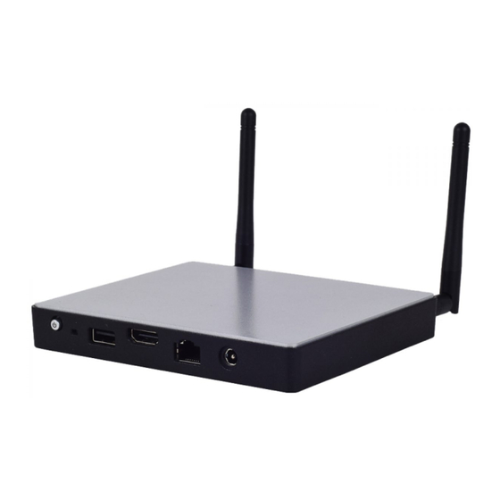
- Page 17 NCA-1020 User Manual Description Antenna 2 x SMA antenna holes 3 x RJ-45 LAN ports (1 pair of bypass) 1 x USB 3.0 Type-A port...
-
Page 18: Chapter 3: Board Layout
Chapter 3: Board Layout... - Page 19 NCA-1020 User Manual...
- Page 20 Chapter 3: Board Layout J20: set the Reset Mode as Hardware (HW) Reset or Software (SW) Reset. Default “short pins” are 2-3 as Software Reset (1x3-pin 2.54mm 3P DIP). Description Description Description HR_RST BTN_RST_N1 SW_GPIO Description Description HW reset SW reset (Default) J7: Battery Pin Header Description...
- Page 21 NCA-1020 User Manual Description Transmitted Data (TxD) 8 7 6 5 4 3 2 1 Received Data (RxD) RJ1/2/3: RJ45 LAN Connectors Description MDI0+ MDI0- MDI1+ MDI2+ 8 7 6 5 4 3 2 1 MDI2- MDI1- MDI3+ MDI3- HDMI: HDMI Connector 19 17 15 13 11 9 7 5 3 1 Description Description...
- Page 22 Chapter 3: Board Layout Description 4 3 2 1 C1 C2 C3 CON1: SIM Slot Description Description PAD2 PAD1 C5 C6 C7 LPC1: Debug port Description Description CLK_33M_P80 LPC_AD1 PLTRST_PORT80_N LPC_AD0 LPC_FRAME_N P3V3 LPC_AD3 Key ping LPC_AD2...
- Page 23 NCA-1020 User Manual MPCIE1: Mini PCIe Socket(PCIE & USB) Description Description WAKE 3.3V 1.5V CLKREQ CLK- CLK+ RESET PCIE_RX- 3.3V PCIE_RX+ 1.5V SMB_CLK PCIE_TX- SMB_DAT PCIE_TX+ USB_D- USB_D+ 3.3V 3.3V 1.5V 3.3V...
- Page 24 Chapter 3: Board Layout MPCIE2: Mini PCIe Socket(mSATA) Description Description 3.3V 3.3V 3.3V 3.3V 3.3V...
- Page 25 NCA-1020 User Manual To access some components and perform certain service procedures, you must perform the following procedures first. Warning: 1. To reduce the risk of personal injury, electric shock, or damage to the equipment, please remove all power sources. 2. Please wear ESD protected gloves before conducting the following steps.
-
Page 26: Chapter 4: Hardware Setup
Chapter 4: Hardware Setup Remove the SSD bracket in order to install hardware components and SSD. Remove the bracket... - Page 27 NCA-1020 User Manual The motherboard supports a 204-pin DIMM DDR3L 1600 MHz non-ECC up to 8GB, which is located on the bottom side of the motherboard. Please follow the steps below to install the DIMM memory module properly. Note: you may have to remove the SSD installation bracket first. Assuming that the previous steps, including system power-off, lifting the chassis and removal of the SSD bracket, have been taken properly, then remove the 4 screws at the four corners that secure the motherboard.
- Page 28 Chapter 4: Hardware Setup Locate the DIMM socket at the back of the motherboard. Align the DIMM module and make sure the notches of the module aligned with the socket keys in the slot. Insert the module into the slot at a diagonal angle and press it down until it’s firmly seated by the clips at both sides.
- Page 29 NCA-1020 User Manual The motherboard provides two mini-PCIe sockets: a mini-PCIe socket with USB and PCIe signals and an mSATA mini socket. Please follow the procedures below for installation. Note: You may have to remove the SSD installation bracket first. Locate the mini-PCIe sockets.
- Page 30 Chapter 4: Hardware Setup The system supports 1 x 2.5” SATA SSD as data storage (SSD is recommended due to heat and vibration concerns). Please follow the steps below for installation. Attach a SATA 2.5” SSD onto the SSD bracket. Note: the SSD bracket should have been removed in previous steps.
- Page 31 NCA-1020 User Manual Make sure the screw holes are aligned and then apply screws to secure the installation between the SSD and the bracket. Remove the bracket Place the SSD-installed bracket back onto the motherboard. Make sure the screw holes are aligned. Connect the SATA signal and power cables.
-
Page 32: Front Panel
Chapter 4: Hardware Setup The system can be customized to enable SMA antenna connectivity. Please follow the steps below to install the antenna. Plug the female connector of the SMA antenna cable to the “MAIN” and “ALT” connectors (antenna connector of a wireless network module), as shown in the image below. Plug the male connector of the SMA antenna onto the designated port as shown in the image below. - Page 33 With the Rack mount Kit, this system can be fixed onto the post along with the system’s power adapter. This rack mount assembly is designed to hold up to three NCA-1020 systems. Please contact Lanner‘s sales representative for this kit.
- Page 34 Chapter 4: Hardware Setup 1. Fix the system onto the tray using four long screws. Flip over the tray to locate the screw holes as shown below. 2. Flip the tray back to the up-front side and lock the adapter holder along with the power adapter onto the tray using two short screws.
- Page 35 NCA-1020 User Manual 5. (Optional) Attach the ear extension brackets to both ears of the tray and fix them using the screws provided. Fix the tray onto the rack using the mounting screws provided.
-
Page 36: Chapter 5: Bios Setup
Chapter 5: BIOS Setup BIOS is a firmware embedded on an exclusive chip on the system’s motherboard. Lanner's BIOS firmware offering including market-proven technologies such as Secure Boot and Intel Boot Guard technology deliver solid commitments for the shield protection against malware, uncertified sequences and other named cyber threats. - Page 37 NCA-1020 User Manual Setup main page contains BIOS information and project version information. Feature Description BIOS Vendor: American Megatrends Core Version: AMI Kernel version, CRB code base, X64 BIOS Compliancy: UEFI version, PI version Information Project Version: BIOS release version Build Date and Time: MM/DD/YYYY Access Level: Administrator / User To set the Date, use <Tab>...
-
Page 38: Advanced
Chapter 5: BIOS Setup Select the Advanced menu item from the BIOS setup screen to enter the “Advanced” setup screen. Users can select any of the items in the left frame of the screen. -
Page 39: Security
NCA-1020 User Manual Feature Options Description Enables or disables BIOS support for security device. Security Device Enabled By disabling this function, OS will not show Security Support Disabled Device. TCG EFI protocol and INT1A interface will not be available. Enables or disables Security Device. Enabled TPM State NOTE: Your computer will reboot during restart in... - Page 40 Chapter 5: BIOS Setup...
- Page 41 NCA-1020 User Manual Feature Options Description COM0 Enabled Console Enables or disables Console Redirection Disabled Redirection...
- Page 42 Chapter 5: BIOS Setup Console Redirection Settings Feature Options Description VT100: ASCII char set VT100 VT100+:Extends VT100 to support color, VT100+ function keys, etc. Terminal Type VT-UTF8 VT-UTF8:Uses UTF8 encoding to map ANSI Unicode chars onto 1 or more bytes ANSI: Extended ASCII char set 9600 Selects serial port transmission speed.
- Page 43 NCA-1020 User Manual VT-UTF8 Combo Disabled Enables VT-UTF8 Combination Key Support Key Support Enabled for ANSI/VT100 terminals Disabled With this mode enabled, only text will be Recorder Mode Enabled sent. This is to capture Terminal data. Disabled Enables or disables extended terminal Resolution 100x31 Enabled resolution...
- Page 44 Chapter 5: BIOS Setup Feature Options Description COM0 Enabled Console Enables or disables Console Redirection Disabled Redirection...
- Page 45 NCA-1020 User Manual Console Redirection Settings Feature Options Description VT100: ASCII char set VT100 VT100+:Extends VT100 to support color, VT100+ function keys, etc. Terminal Type VT-UTF8 VT-UTF8:Uses UTF8 encoding ANSI Unicode chars onto 1 or more bytes ANSI: Extended ASCII char set 9600 19200 Selects serial port transmission speed.
- Page 46 Chapter 5: BIOS Setup VT-UTF8 Combo Disabled Enables VT-UTF8 Combination Key Support Key Support Enabled for ANSI/VT100 terminals Disabled With this mode enabled, only text will be Recorder Mode Enabled sent. This is to capture Terminal data. Disabled Enables or disables extended terminal Resolution 100x31 Enabled resolution...
- Page 47 NCA-1020 User Manual Feature Options Description Disabled STAT Controller Enable/Disable SATA Device Enabled SATA Mode Selection AHCI Determines how SATA controller operate. Gen1 Select SATA Interface Speed, CHV A1 SATA Interface Speed Gen2 always with Gen1 Speed. Gen3 Aggressive LPM Enabled Enable PCH to aggressively enter link Support...
- Page 48 Chapter 5: BIOS Setup Feature Options Description Disabled CSM Support Enables or disables CSM Support Enabled UPON REQUEST - GA20 can be disabled Upon Request using BIOS services. ALWAYS - do not GateA20 Active Always allow disabling GA20; this option is useful when any RT code is executed above 1MB.
- Page 49 NCA-1020 User Manual UEFI Storage OpROM Legacy Do Not Launch Controls the execution of UEFI and Legacy Video UEFI Video OpROM Legacy Do Not Launch Determines OpROM execution policy for Other PCI device UEFI devices other than Network, Storage, or Legacy Video...
-
Page 50: Device Reset Time-Out
Chapter 5: BIOS Setup Feature Options Description Enables Legacy USB support. Enabled Auto option disables legacy support if no Legacy USB Support Disabled USB devices are connected; Auto Disabled option will keep USB devices available only for EFI applications. This is a workaround for OSes without Enabled XHCI hand-off... - Page 51 NCA-1020 User Manual Maximum time the device will take before it properly reports itself to the Host Auto Device power-up delay Controller. Auto uses default value: for a Manual Root port, it is 100 ms, for a Hub port the delay is taken from Hub descriptor.
- Page 52 Chapter 5: BIOS Setup Feature Options Description Disabled Control LAN1 Legacy PXE Control Legacy PXE Boot from which Lan LAN2 Boot from LAN3...
- Page 53 NCA-1020 User Manual Runtime Bypass Control Feature Options Description LAN pair 1 Enabled LAN bypass control after Power-ON. Bypass Disabled PowerOff Bypass Control Feature Options Description LAN pair 1 Enabled LAN Bypass control after Power-Off. Bypass Disabled...
- Page 54 Chapter 5: BIOS Setup Select the Chipset menu item from the BIOS setup screen to enter the Platform Setup screen. Users can select any of the items in the left frame of the screen.
- Page 55 NCA-1020 User Manual Feature Options Description 2 GB 2.25 GB Max TOLUD 2.5 GB Maximum Value of TOLUD. 2.75 GB 3 GB...
- Page 56 Chapter 5: BIOS Setup Feature Options Description Power Off Restore AC Power Select AC power state when power is re-applied after Power On Loss a power failure. Last State Quiet Serial IRQ Mode Configure Serial IRQ Mode. Continuous...
- Page 57 NCA-1020 User Manual Select the Security menu item from the BIOS setup screen to enter the Security Setup screen. Users can select any of the items in the left frame of the screen. Feature Description If ONLY the Administrator's password is set, it only limits access to Setup and is only asked for when Administrator Password entering Setup.
- Page 58 Chapter 5: BIOS Setup Feature Options Description Secure Boot can be enabled if 1.System running in Secure Boot Disabled User mode with enrolled Platform Key(PK) 2.CSM control Enabled function is disabled Secure Boot mode selector. 'Custom' Mode Standard Secure Boot Mode enables users to change Image Execution policy Custom and manage Secure Boot Keys...
- Page 59 NCA-1020 User Manual Key Management Feature Options Description Provision Factory Disabled Install factory default Secure Boot keys when Default keys Enabled System is in Setup Mode Enroll all Factory Force System to User Mode - install all Factory None Default keys Default keys...
- Page 60 Chapter 5: BIOS Setup Select the Boot menu item from the BIOS setup screen to enter the Boot Setup screen. Users can select any of the items in the left frame of the screen. Feature Options Description The number of seconds to wait for setup Setup Prompt Timeout activation key.
-
Page 61: Save And Exit Menu
Select the Save and Exit menu item from the BIOS setup screen to enter the Save and Exit Setup screen. Users can select any of the items in the left frame of the screen. ■ Discard Changes and Exit Select this option to quit Setup without saving any modifications to the system configuration. The following window will appear after the “Discard Changes and Exit”... - Page 62 NCA-1020 User Manual ■ Restore Defaults Restore default values for all setup options. Select “Yes” to load Optimized defaults. Note: The items under Boot Override were not same with image. It should depend on devices connected to this system.
-
Page 63: Appendix A: Programming Watchdog Timer
, and the processor’s reset signal is asserted. Thus, the processor will be restarted as if a human operator had cycled the power. For sample watchdog code, please visit Lanner Support Website at http://www.lannerinc.com/download-center/ and browse the download center. - Page 64 NCA-1020 User Manual Console redirection lets you monitor and configure a system from a remote terminal computer by re-directing keyboard input and text output through the serial port. The following steps illustrate how to use this feature. The BIOS of the system allows the redirection of the console I/O to a serial port. With this configured, you can remotely access the entire boot sequence through a console port.
-
Page 65: Appendix C: Programming The Lcm
2 lines, 16 (or 20) characters per line. • USB and Serial Text or Graphic-based LCM: Our next generation LCM. Lanner engineers design a common source code to be deployed on these two differently interfaced LCM modules. Jumpers are used to select between text and graphic types. - Page 66 Display Off turning off the LCM display Cursor Off/On NOT showing/showing the cursor on the LCM display Blinking off/On turning off/on the cursor blinking Writing “Lanner@Taiwan” displaying the specific sentences Reading “Lanner@Taiwan” reading the specific sentence CGram Test displaying the user-stored characters...
- Page 67 Appendix C: Programming the LCM — Get the keypad input: the 1st button is read in as Left, the 2nd button is read in as Up, the 3rd button is read in as Right, and the 4th button is read in as Down. —...
- Page 68 NCA-1020 User Manual 1. Make sure that the Guest OS has been installed. 2. Add the following 4 lines into the xml file (for example, add to /etc/libvirt/qemu/<yourvirtualmachine>.xml in linux KVM): <parallel type=’dev’> <source path=’/dev/parport0’/> <target port=’0’/> </parallel> 3. Open a terminal in the Guest OS and then issue the following commands to install Linux Kernel drivers. # modprobe parport # modprobe parport_pc # modprobe ppdev...
-
Page 69: Appendix D: Terms And Conditions
Appendix D: Terms and Conditions 1. All products are under warranty against defects in materials and workmanship for a period of one year from the date of purchase. 2. The buyer will bear the return freight charges for goods returned for repair within the warranty period; whereas the manufacturer will bear the after service freight charges for goods returned to the user. - Page 70 NCA-1020 User Manual When requesting RMA service, please fill out the following form. Without this form enclosed, your RMA cannot be processed.
Need help?
Do you have a question about the NCA-1020A and is the answer not in the manual?
Questions and answers