Advertisement
Quick Links
Advertisement

Related Manuals for Lanner NCA-4035


Summary of Contents for Lanner NCA-4035
- Page 1 Network Appliance Platforms NCA-4035 User Manual Version: 1.0 Date of Release: 2022-11-03...
- Page 2 - assumed to be qualified in the servicing of computer equipment, such as professional system integrators, or service personnel and technicians. The latest version of this document can be found on Lanner’s official website, available either through the product page or through the Lanner Download Center page with a login account and password.
- Page 3 NCA-4035 User Manual Taiwan Corporate Headquarters China Lanner Electronics Inc. Beijing L&S Lancom Platform Tech. Co., Ltd. 7F, No.173, Sec.2, Datong Rd. Guodong LOFT 9 Layer No. 9 Huinan Road, Xizhi District, New Taipei City 22184, Huilongguan Town, Changping District, Beijing...
- Page 4 NCA-4035 User Manual Intel® and Intel® Celeron® are trademarks of Intel Corporation or its subsidiaries in the U.S. and/or other countries. Microsoft Windows and MS-DOS are registered trademarks of Microsoft Corp. All other product names or trademarks are properties of their respective owners.
- Page 5 NCA-4035 User Manual Portez des lunettes de sécurité pour protéger vos yeux. N’effectuez aucune action qui pourrait créer un danger pour d’autres ou rendre l’équipement dangereux. Coupez complètement l’alimentation en éteignant l’alimentation et en débranchant le cordon d’alimentation avant d’installer ou de retirer un châssis ou de travailler à proximité de sources d’alimentation.
- Page 6 The installation of this product must be performed by trained specialists; otherwise, a non-specialist might create the risk of the system’s falling to the ground or other damages. Lanner Electronics Inc. shall not be held liable for any losses resulting from insufficient strength for supporting the system or use of inappropriate installation components.
- Page 7 NCA-4035 User Manual Before turning on the device, ground the grounding cable of the equipment. Proper grounding (grounding) is very important to protect the equipment against the harmful effects of external noise and to reduce the risk of electrocution in the event of a lightning strike.
- Page 8 NCA-4035 User Manual Package Content ..........................10 Ordering Information ........................10 Optional Accessories ........................10 System Specifications ........................11 Front Panel ............................. 12 Rear Panel ............................13 Block Diagram ..........................14 Jumpers and Connectors ........................ 15 Opening the Chassis ........................29 Installing the System Memory .......................
- Page 9 NCA-4035 User Manual IPMI Commands Support List ......................46 Using BMC Web UI ......................... 48 Wizard Welcome Page Introduction ....................50 Web UI Layout Introduction ......................51 Main Page ............................54 Advanced ............................55 Platform ............................75 Socket ............................. 79 Server Mgmt ...........................
- Page 10 NCA-4035 User Manual The NCA-4035 is based on Intel® Xeon D, a branch of Xeon processors optimized for delivering ultra-low power consumption and robust performance. This appliance comes with the most innovative System-on-a- Chip built for the edge and is ideal for applications in networking, 5G and IoT/IIoT Edge computing, delivering improvement in packet processing performance, virtualized Customer Premise Equipment (vCPE) usages.
- Page 11 NCA-4035 User Manual Form Factor 1U 19” Rackmount SKU A: Intel® D-2798NT, 20C, 125W SKU B: Intel® D-2776NT, 16C, 117W Processor Options SKU C: Intel® D-2753NT, 12C, 87W Platform SKU D: Intel® D-2733NT, 8C, 80W SKU E: Intel® D-2712T, 4C, 65W...
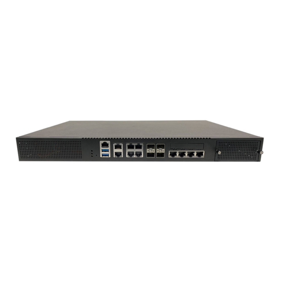
- Page 12 NCA-4035 User Manual Description LED Indicators Power/Status/Storage, pls refer to Appendix A Reset Button 1x Reset Button Console Port 1x RJ45 Console Port USB Port 2x USB 3.0 Ports LAN Port 1x RJ45 GbE LAN via I210-AT LOM Port 1x RJ45 GbE LOM Port...
- Page 13 NCA-4035 User Manual Description PCIe Expansion Slot PCIe*16 via 2x Slim SAS Connector (FHHL) (Optional) Cooling Fan 4x Cooling Fans SKU A/B/C/D : 2x 300W AC Redundant PSU (N+1 design) Redundant PSU SKU E : 1x 350W Single AC PSU...
- Page 14 NCA-4035 User Manual 2x M.2 2280 SATA SSD M.2 2242 SATA SSD SATA3.0 2x SATA3.0 DDR4 80 debug ports BIOS BIOS SlimSAS PCIe Ice Lake-D HCC GPIO SlimSAS UART others NCSI 2x PCIEx1 1x PCIEx4 1x PCIEx4 USB3.0 GPIO console Intel not support.
- Page 15 NCA-4035 User Manual The following references the pin assignments and internal connectors of the system.
- Page 16 NCA-4035 User Manual CMOS1: Clear CMOS CMOS1 Description Normal (Default) Clear CMOS JPWR1: External Power Button (1x2 Pin 2.43mm Wafer) Description PS_IN JRST1: Reset Mode Select Description Hardware Reset Software Reset JDUAL1: Select CS for Flash Fixture Pin/Switch Description 1-2 Short,...
- Page 17 NCA-4035 User Manual RJ1: Dual RJ-45 with LED Pin No. Description Fast E-Net Giga Net MD0+ MD0- MD1+ MD2+ MD2- MD1- MD3+ MD3- 10-/100-/1000+ 10+/100+/1000- Link+/ACT- Link-/ACT+ LAN1: 2x2 Port RJ-45 with LED Pin No. Description Fast E-Net Giga Net...
- Page 18 NCA-4035 User Manual MD1+ MD2+ MD2- MD1- MD3+ MD3- 10-/100-/1000+ 10+/100+/1000- Link+/ACT- Link-/ACT+ SFP1/SFP2: SFP28 2x1 Assy with LED Description Description VeeT VeeR TxFault TxDis VeeR VCCR MOD_ABS VCCT VeeT RX_LOS VeeR VeeT JLAN1: Minimezz Connector Description Description 5VSB CR_RX0-...
- Page 19 NCA-4035 User Manual PLT_RST# 3VSB PRESNT# MDIO 12VSB 12VSB INT# GBE_SCL GBE_RST# GBE_SDA CR_TX0+ CR_TX0- CR_TX2+ CR_TX2- CR_TX1+ CR_TX1- CR_TX3+ CR_TX3- 12VSB 12VSB...
- Page 20 NCA-4035 User Manual JUSBCOM1: USB3.0 Double Stack Type A+ Console Port Connector Description Description USB_VCC1 USB3.0_RX- USB3.0_RX+ USB3.0_TX- USB3.0_X+ JCOM2: COM2 (Pin Header) Description DCD# DSR# CTS#...
- Page 21 NCA-4035 User Manual JPCIEG1/JPCIEG2: SFF-8645 Connector for PCIE Cable Description Description PCIE_CLK0P PCIE_RX0P PCIE_CLK0N PCIE_RX0N PCIE_TX0P PCIE_RX1P PCIE_TX0N PCIE_RX1N PCIE_TX1P PCIE_RX2P PCIE_TX1N PCIE_RX2N PCIE_TX2P PCIE_RX3P PCIE_TX2N PCIE_RX3N PCIE_TX3P PCIE_RX4P PCIE_TX3N PCIE_RX4N PCIE_TX4P PCIE_RX5P PCIE_TX4N PCIE_RX5N PCIE_TX5P PCIE_RX6P PCIE_TX5N PCIE_RX6N PCIE_TX6P...
- Page 22 NCA-4035 User Manual PLT_RST# 3VSB OPMA1: DDR4 OPMA Pin Define Not Standard DIMM Socket OPMA Name OPMA Name Card detect P12V_ADC11 / GPIX3 GND1 RSVD9 I2C_SCL8 / GPIOK6 SYS_UART2_DCD I2C_SDA8 / GPIOK7 SYS_UART2_DSR RSVD1 SYS_UART2_CTS RSVD2 SYS_UART2_RI TACH4 / GPIOO4...
- Page 23 NCA-4035 User Manual SYS_UART2_RXD RSVD13 SYS_UART2_TXD GND36 SYS_UART2_RTS I2C_SCL5_Transceiver/others SYS_UART2_DTR I2C_SDA5_Transceiver/others GND8 GND37 RSVD5 PWM2 / GPION2 GND9 PWM4 / GPION4 TACH8 / GPIOP0 GND38 TACH7 / GPIOO7 RSVD14 TACH5 / GPIOO5 PECI_VDD TACH9 / GPIOP1 PECI TACH6 / GPIOO6...
- Page 24 NCA-4035 User Manual PEREFCLKN GND45 GND15 SOL_UART_DCD SOL_UART_DSR SOL_UART_RI SOL_UART_DTR SOL_UART_RTS GND16 GND46 SYSCS# / GPIOI0 SYS_UART_SWITCH_OUT SYSMISO / GPIOI3 BIOS_READY_IN SYSCK / GPIOI1 BMC_PWRBTN_OUT SYSMOSI / GPIOI2 BMC_READY_OUT GND17 SYS_NMI_IN GND18 GND47 SYS_SMI_IN BMC_SMI_OUT MDC2 / GPIOA6 / CPU_CATERR_IN...
- Page 25 NCA-4035 User Manual CPU_ERR_1_IN I2C_SCL4_PMBus CPU_ERR_2_IN I2C_SDA4_PMBus GND31 GND52 USB2A_DP BMC_NMI_OUT USB2A_DN CPU1_PROCHOT_IN GND22 GND53 RSVD7 LAN_100M# RSVD8 LAN_ACT# GND23 LAN_1G# SOL_CTS3 GND54 SOL_TXD3 GPIOA1_MAC2LINK SOL_RXD3 RGMII2RXD3 / RMII2RXER / GPIOV7 GND24 RGMII2RXD0 / RMII2RXD0 / GPIOV4 MDI0P RGMII2RXCK / RMII2RCLKI / GPIOV2...
- Page 26 NCA-4035 User Manual JNGFF1 / JNGFF2 / JNGFF3: M.2 Slot (M-Key) Description Description M.2 LED SATA_RX+ SATA_RX- SATA_TX- SATA_TX+ M-Key PEDET...
- Page 27 NCA-4035 User Manual JSATA1 / JSATA2: Connector (w/ SATA DOM) Description ATX1: 2x12 24P ATX Connector Description Description 3.3V 3.3V 3.3V PS_ON# PWR_OK 5VSB 3.3V ATX2: 2x4 8P 12V2D ATX Connector Description Description JSATAPW1 / JSATAPW2: SATA HDD Power Connector...
- Page 28 NCA-4035 User Manual Fan1 / Fan2 / Fan3 / Fan4: Fan Connector Description FAN_TECH_IN1 FAN_TECH_IN2 FAN SPEEC CTRL JATX1 / JATX2 / JATX3: 2x2 4P PCIE Power Connector Description Description 3.3V JSPI_TPM1: SPI Interface (w/ SPI TPM Function) Description Description...
- Page 29 NCA-4035 User Manual To reduce the risk of personal injury, electric shock, or damage to the system, please remove all power connections to shut down the device completely and wear ESD protection gloves when handling the installation steps. 1. Power off the system and remove all power connections.
- Page 30 NCA-4035 User Manual The motherboard supports 4x memory slots for DDR4 UDIMM/RDIMM. Please follow the steps below to install the DIMM memory module properly. Total Slots Number of Channels 2 (2 DIMMs per channel) Supported DIMM Capacity 4GB, 8GB, 16GB, 32GB, 64GB...
- Page 31 NCA-4035 User Manual 1. Power off the system, open the chassis cover. 2. Locate the DIMM memory slots. 3. Pull open the white DIMM slot latches. 4. Align the notch of the module with the socket key in the slot and carefully insert the card into the slot.
- Page 32 NCA-4035 User Manual The system supports three M.2 slots for additional data storage with two M.2 2280 B-Key and one M.2 2242 B-Key. Please follow the steps for installation. 1. Power off the system and open the chassis cover. 2. Locate the two M.2 2280 slots on the motherboard.
- Page 33 NCA-4035 User Manual 1. Power off the system and open the chassis cover. 2. Locate the one M.2 2242 slot on the motherboard. 3. Align the notch of the storage card with the socket key in the pin slot. Notch 4.
- Page 34 NCA-4035 User Manual IPMI provides better server management, server monitoring, and remote access. IPMI is independent of the system’s CPU operating system via hardware applied directly into the motherboard. Please follow the steps for installation. 1. Power off the system and open the chassis cover.
- Page 35 NCA-4035 User Manual The system provides one slot for a TPM module card to provide hardware-based security related functions. Follow the steps below for installations. 1. Power off the system and open the chassis cover. 2. Locate the TPM connector pins on the motherboard.
- Page 36 NCA-4035 User Manual NCA-4035 comes with one NIC module slot for expansion. Follow the steps for installation. 1. Locate the NIC module slot on the front panel of the system. 2. Rotate clockwise and loosen the two lock-screws, and remove the NIC module slot door.
- Page 37 NCA-4035 User Manual Power supply units may wear down eventually. The system supports 300W 1+1 redundant PSUs or a 350W single PSU, depending on order preferences. Please prepare the replacement power supply units matching this capacity. 1. Power off the system. Locate the power supply unit(s) on the rear panel of the system.
- Page 38 NCA-4035 User Manual There are two methods for installing this system into a rack: With Mounting Ear Brackets only This method is quick and easy by fixing this system to the front posts of the rack, but it also makes servicing the system more difficult.
- Page 39 NCA-4035 User Manual 1. Check the accessory pack for the following items: 1x Screw Pack 2x Ear Brackets Screw Pack Ear Brackets 2. Align the bracket to the side of the chassis and make sure the screw-holes are matched, and then secure the bracket onto the chassis with three provided screws.
- Page 40 NCA-4035 User Manual 1. Check the package contents of the Slide Rail Kit. The kit shall include the following items: 1x pack of M4X4L screws (for 7.1 Round Hole Screws M4X4L Screws securing the Rail Brackets on the system) 1x pack of 7.1 Round Hole...
- Page 41 NCA-4035 User Manual 5. Align the bracket to the side of the chassis and make sure the screw- holes are matched, and then secure the bracket onto the chassis with three provided M4X4L screws. Align the screws with the holes indicated on the brackets and the screw holes on the side of the chassis.
- Page 42 NCA-4035 User Manual 9. For the rear rack installation, slide the rail to aim and engage the bolts on the rail’s rear end with the two available holes on the post, and the rail assembly will click into place. Click 10.
- Page 43 NCA-4035 User Manual 12. While pushing in the system, also push and hold the Rail Lock tab on both brackets. Rail Lock Push the system all the way in until it stops. To remove the system from the rack, gently pull it outwards, towards you, while pushing the Release Tab on both sides of the brackets.
-
Page 44: Standard Features
NCA-4035 User Manual This chapter will introduce the features of Lanner’s BMC firmware and how to perform server remote management through it. Lanner has implemented IPMI 2.0 based on ASPEED service processor, performing all the BMC defined by IPMI 2.0. Additionally, Lanner’s BMC firmware runs an embedded web-server for full configuration using Web UI, which as a low learning curve. - Page 45 NCA-4035 User Manual The BMC implements system sensor monitoring feature. It could monitor voltage, temperature, and current of critical components. The BMC implements chassis power and resets functions for system administrators to control and manage the system power behavior. These functions can be activated by sending the IPMI 2.0 compatible chassis commands to the BMC over messaging interfaces.
- Page 46 NCA-4035 User Manual COMMANDS NETFN IPM Device “Global” Commands Get Device ID APP (06h) Cold Reset APP (06h) Warm Reset APP (06h) Get Device GUID APP (06h) BMC Watchdog Timer Commands Reset Watchdog Timer APP (06h) Set Watchdog Timer APP (06h)
- Page 47 NCA-4035 User Manual Delete SEL Entry Storage (0Ah) Clear SEL Storage (0Ah) Get SEL Time Storage (0Ah) Set SEL Time Storage (0Ah) Get SEL Time UTC Offset Storage (0Ah) Set SEL Time UTC Offset Storage (0Ah) LAN Device Commands Set LAN Configuration Parameters...
-
Page 48: Default Username And Password
NCA-4035 User Manual In the address bar of your Internet browser, input the IP address of the remote server to access the BMC interface of that server. Initial access of BMC prompts you to enter username and password. A screenshot of the login screen is given... - Page 49 NCA-4035 User Manual Change the default password - Dialog Clicking OK will take you to set a new password. Change the default password – Set password Note: Duplicate usernames shouldn’t exist across various authentication methods like LDAP, RADIUS or IPMI since the privilege of one Authentication method is overwritten by another authentication...
- Page 50 NCA-4035 User Manual After the first-time login, you will see first time wizard welcome page as the following picture. Please press the “Next” button and configure your BMC step by step. 1. On the “IPv4”, “IPv6” and “DNS” pages, you could specify the hostname and network settings of BMC.
- Page 51 NCA-4035 User Manual The BMC Web UI consists of various menu items: The menu bar displays the following: Dashboard Appliance – Sensor Reading Appliance – Event Log Appliance – Remote Media Settings Appliance – KVM RMedia Settings Appliance – Image Redirection BMC Config –...
- Page 52 NCA-4035 User Manual The user information and quick buttons are located at the top right of the Web UI. User Information Logged-in user information: Click the icon to view the logged-in user information. A screenshot of the logged-in user information is shown below: Logged-in User Information The logged-in user information shows the logged-in user’s username, privilege, with the quick buttons allowing...
- Page 53 NCA-4035 User Manual BIOS is a firmware embedded on an exclusive chip on the system’s motherboard. Lanner's BIOS firmware offering including market-proven technologies such as Secure Boot and Intel Boot Guard technology deliver solid commitments for the shield protection against malware, uncertified sequences and other named cyber threats.
- Page 54 NCA-4035 User Manual Setup main page contains BIOS information and project version information. Feature Description BIOS Vendor: American Megatrends Core Version: AMI Kernel version, CRB code base, X64 Compliancy: UEFI version, PI version BIOS Information Project Version: BIOS release version...
- Page 55 NCA-4035 User Manual Select the Advanced menu item from the BIOS setup screen to enter the “Advanced” setup screen. Users can select any of the items in the left frame of the screen.
- Page 56 NCA-4035 User Manual Feature Options Description Enables or disables BIOS support for security device. By Security Device Enabled disabling this function, OS will not show Security Device. Support Disabled TCG EFI protocol and INT1A interface will not be available.
- Page 57 NCA-4035 User Manual Feature Options Description Enables or disables BIOS support for security device. By disabling Security Device Enabled this function, OS will not show Security Device. TCG EFI protocol Support Disabled and INT1A interface will not be available. Enables or disables Security Device.
- Page 58 NCA-4035 User Manual Feature Options Description Enables or disables BIOS support for security device. By Security Device Enabled disabling this function, OS will not show Security Device. TCG Support Disabled EFI protocol and INT1A interface will not be available. Enabled SHA-1 PCR Bank Enables or disables SHA-1 PCR Bank.
- Page 59 NCA-4035 User Manual Platform Enabled Enables or disables Platform Hierarchy. Hierarchy Disabled Enabled Storage Hierarchy Enables or disables Storage Hierarchy. Disabled Endorsement Enabled Enables or disables Endorsement Hierarchy. Hierarchy Disabled Select the TCG2 Spec Version, TPM2.0 UEFI Spec TCG_1_2 TCG_1_2: Supports the Compatible mode for Win8/Win10...
- Page 60 NCA-4035 User Manual...
- Page 61 NCA-4035 User Manual Feature Options Description Enabled Serial Port Enables or disables Serial Port 1. Disabled Device Settings IO=3F8h; IRQ = 4...
- Page 62 NCA-4035 User Manual Feature Options Description Enabled Serial Port Enables or Disables Serial Port 2 Disabled Device Settings IO=2F8h; IRQ=4...
- Page 63 NCA-4035 User Manual Feature Options Description Smart Fan Mode None Smart Fan Parameters Configuration...
- Page 64 NCA-4035 User Manual Feature Options Description Manual Mode Smart Fan Mode Smart Fan Mode select Smart Fan Mode Target Temperature T1 Input Target Temperature (Range:0 - 127) Target Temperature T2 Input Target Temperature (Range:0 - 127) Target Temperature T3 Input Target Temperature (Range:0 - 127)
- Page 65 NCA-4035 User Manual Feature Options Description Enabled COM0 Console Redirection Enables or disables Console Redirection Disabled Feature Options Description Enabled COM1 Console Redirection Enables or disables Console Redirection Disabled...
- Page 66 NCA-4035 User Manual Feature Options Description VT100: ASCII char set VT100 VT100+:Extends VT100 to support color, function keys, etc. VT100+ Terminal Type VT-UTF8:Uses UTF8 encoding to map Unicode chars onto 1 or VT-UTF8 more bytes ANSI ANSI: Extended ASCII char set...
- Page 67 NCA-4035 User Manual Disabled With this mode enabled, only text will be sent. This is to capture Recorder Mode Terminal data. Enabled Disabled Resolution 100x31 Enables or disables extended terminal resolution Enabled VT100 LINUX XTERM86 Putty KeyPad Selects FunctionKey and KeyPad on Putty.
- Page 68 NCA-4035 User Manual Feature Options Description Legacy Serial Select a COM port to display redirection of Legacy OS and COM0 Redirection Port Legacy OPROM Messages Legacy OS 80x24 On Legacy OS, the Number of Rows and Columns 80x25 Redirection Resolution supported redirection.
- Page 69 NCA-4035 User Manual Feature Options Description Enables or disables 64bit capable Devices to be Decoded in Above 4G Disabled Above 4G Address Space (Only if System Supports 64 bit PCI Decoding Enabled Decoding) Disabled If the system has SR-IOV capable PCIe Devices, this option...
- Page 70 NCA-4035 User Manual Feature Options Description Enables Legacy USB support. Enabled Auto option disables legacy support if no USB devices are Legacy USB Disabled connected; Support Auto Disabledoption will keep USB devices available only for EFI applications. Enabled This is a workaround for OSes without XHCI hand-off...
- Page 71 NCA-4035 User Manual Feature Options Description Disabled Network Stack Enables or disables UEFI Network Stack Enabled Disabled Enables Ipv4 PXE Boot Support. If IPV4 is disabled, PXE boot Ipv4 PXE Support option will not be created. Enabled Disabled Enables Ipv4 HTTP Boot Support. If IPV4 is disabled, HTTP Ipv4 HTTP Support boot option will not be created.
- Page 72 NCA-4035 User Manual Feature Options Description Disabled CSM Support Enables or disables CSM Support Enabled Do Not Launch Network Controls the execution of UEFI and Legacy PXE OpROM UEFI Legacy Do Not Launch Controls the execution of UEFI and Legacy Storage...
- Page 73 NCA-4035 User Manual...
- Page 74 NCA-4035 User Manual Feature Options Description Disabled Control Legacy Select On Board LAN# Boot LAN1 PXE Boot from LAN2...
- Page 75 NCA-4035 User Manual Select the Platform menu item from the BIOS setup screen to enter the Platform Setup screen. Users can select any of the items in the left frame of the screen. Feature Options Description PCH-IO None Displays and provides option to change the PCH Settings...
- Page 76 NCA-4035 User Manual Feature Options Description SATA Configuration None SATA devices and settings Power ON Restore AC Power Off Select S0/S5 for ACPI state after a G3 Power Loss Last State Quiet Serial IRQ Mode Configure Serial IRQ Mode. Continuous...
- Page 77 NCA-4035 User Manual Feature Options Description Disabled SATA Controller Enables or disables SATA Controller Enabled AHCI Configure SATA as This will configure SATA as RAID or AHCI. RAID Disabled Port 0/1/2/3/4 Enable or Disable SATA Port Enabled Disabled Hot Plug Designates this port as Hot Pluggable.
- Page 78 NCA-4035 User Manual...
- Page 79 NCA-4035 User Manual Select the Socket menu item from the BIOS setup screen to enter the Socket Setup screen. Users can select any of the items in the left frame of the screen. Feature Options Description Displays and provides option to change the Processor...
- Page 80 NCA-4035 User Manual...
- Page 81 NCA-4035 User Manual Feature Options Description Hyper-Threading Enables Hyper Threading (Software Method to Disabled Enabled [ALL] Enable/Disable Logical Processor threads. Disabled Machine Check Enable or Disable the Machine Check Enabled Disabled Hardware Prefetcher = MLC Streamer Prefetcher (MSR 1A4h Bit[0])
- Page 82 NCA-4035 User Manual Feature Options Description 0: Enable all cores. FFFFFFFFFFF: Disable all cores least one Core Disable core per CPU must be enabled. Disabling all cores is an Bitmap (Hex) invalid configuration.
- Page 83 NCA-4035 User Manual Feature Options Description Auto 1200 1333 1400 1600 Maximum Memory Frequency Selections in Mhz. Do not 1800 Memory Frequency select Reserved 1866 2000 2133 2200 2400 2600 Displays memory topology with Dimm population Memory Topology None information...
- Page 84 NCA-4035 User Manual Feature Options Description Socket0 None None Configuration Intel® VT for Press <Enter> to bring up the Intel? VT for Directed I/O None Directed I/O (VT-d) (VT-d) Configuration menu. PCI-E ASPM Support This option enables / disables the ASPM support for all...
- Page 85 NCA-4035 User Manual Feature Options Description Socket 0 None Settings related to PCI Express Port 1A Port 1A Socket 0 None Settings related to PCI Express Port 2A Port 1C Socket 0 None Settings related to PCI Express Port 2C...
- Page 86 NCA-4035 User Manual Feature Options Description Intel® VT for Press <Enter> to bring up the Intel® VT for Directed I/O Enable Directed I/O (VT-d) (VT-d) Configuration menu. Disable...
- Page 87 NCA-4035 User Manual Feature Options Description P State Control Configuration Sub Menu, include Turbo, XE CPU P State Control None and etc. CPU C State Control None CPU C State setting...
- Page 88 NCA-4035 User Manual Feature Options Description Disabled SpeedStep (Pstates) Enables or disables EIST (P-States) Enabled Max Performance Boot performance Select the performance state that the BIOS will set Max Efficient mode before OS hand off. Set by Intel Node Manager...
- Page 89 NCA-4035 User Manual Feature Options Description CPU C1 auto Disabled Autonomous Core C-State Control demotion Enabled Disabled CPU C6 report Enables or disables CPU C6(ACPI C3) report to OS Enabled Enhanced Halt State Core C1E auto promotion Control. Takes effect after...
- Page 90 NCA-4035 User Manual Select the Server Mgmt menu item from the BIOS setup screen to enter the Server Mgmt Setup screen. Users can select any of the items in the left frame of the screen. Feature Options Description Enabled BMC Support Enable or disables interfaces to communicate with BMC.
- Page 91 NCA-4035 User Manual Do Nothing Configure how the system should respond if the OS Boot Reset OS Wtd Timer Policy Watchdog Timer expires. Not available if OS Boot Watchdog Power Down Timer is disabled. Power Cycle System Event Log Press <Enter> to change the SEL event log configuration.
- Page 92 NCA-4035 User Manual Feature Options Description SEL Components Disabled Enables or disables all features of System Event Enabled Logging during boot. Erase SEL Choose options for erasing SEL. Yes, On next reset Yes, On every reset Do Nothing When SEL is Full Choose options for reactions to a full SEL.
- Page 93 NCA-4035 User Manual Feature Options Description Select to configure LAN channel parameters statically or Unspecified Configuration dynamically (by BIOS or BMC). The unspecified option will Static Address source DynamicBmcDhcp not modify any BMC network parameters during BIOS phase.
- Page 94 NCA-4035 User Manual...
- Page 95 NCA-4035 User Manual Select the Security menu item from the BIOS setup screen to enter the Security Setup screen. Users can select any of the items in the left frame of the screen. Feature Description If ONLY the Administrator's password is set, it only...
- Page 96 NCA-4035 User Manual Feature Options Description Secure Boot is activated when Platform Key(PK) is enrolled, Disabled Secure Boot System mode is User/Deployed, and CSM function is Enabled disabled. Secure Boot mode selector: Standard Secure Boot Mode In Custom mode, Secure Boot Variables can be configured...
- Page 97 NCA-4035 User Manual Feature Options Description Factory Key Provision factory default keys on next re-boot only when Disabled Provision Enabled System in Setup Mode. Restore Factory Force System to User Mode. Configure NVRAM to contain None keys OEM-defined factory default Secure Boot keys.
- Page 98 NCA-4035 User Manual Select the Boot menu item from the BIOS setup screen to enter the Boot Setup screen. Users can select any of the items in the left frame of the screen. Feature Options Description Setup Prompt The Number of seconds to wait for setup activation key.
- Page 99 NCA-4035 User Manual Select the Save and Exit menu item from the BIOS setup screen to enter the Save and Exit Setup screen. Users can select any of the items in the left frame of the screen. ■ Discard Changes and Exit Select this option to quit Setup without saving any modifications to the system configuration.
- Page 100 NCA-4035 User Manual ■ Restore Defaults Restore default values for all setup options. Select “Yes”to load Optimized defaults. PS: The items under Boot Override may not be the same as the image above as it should depend on the devices...
-
Page 101: Appendix A: Led Indicator Explanations
NCA-4035 User Manual APPENDIX A: LED INDICATOR EXPLANATIONS Power / Status / Storage Storage COLOR LED ACTION DESCRIPTION Green Steady System is powered ON Power System is powered OFF Green Steady System is Active Steady System Error Status System is powered OFF... - Page 102 NCA-4035 User Manual 10Gb RJ-45 Define: Speed Green (Active) Green/Amber (Link) 10/100M Blinking / Data access Blinking / Data access ON (Amber) Blinking / Data access ON (Green) 1. When cable is plug-in and network is linked. Both LED will be bright. The behavior is as defined.
- Page 103 To provide increased flexibility and usage protection, Lanner has released the 2nd Gen Dual BIOS function on Lanner appliances. With 2nd Gen Dual BIOS, both the primary BIOS and secondary BIOS can be updated and flashed using the BIOS Tool to run different versions of BIOS ROMS independently for maximum compatibility.
- Page 104 Lanner Technical Support. Warning DO NOT power off or reset the system during BIOS updating process. Disclaimer Under no circumstances will Lanner accept responsibility or liability for damages of any kind whatsoever resulting or arising directly or indirectly from a BIOS update.
- Page 105 NCA-4035 User Manual Define the Alarm and Mute behavior Power Module Power Module Power Cord Fail Remove Remove Buzzer Alarm Alarm Alarm Change back the Good PSU Module Put back the PSU Module Plug-in the Power cord Mute Press the Mute Button...
- Page 106 NCA-4035 User Manual SMART POWER & RESET BUTTON Smart Power and Reset Button – Control by CPLD...
- Page 107 NCA-4035 User Manual ESD/SURGE ENHANCEMENT Electrostatic Discharge Contact Air discharge (ESD): IEC-61000-4-2 discharge Level 1 ±2 kV ±2 kV Level 2 ±4 kV ±4 kV 4K Contact Level 3 ±6 kV ±8 kV 8K Air Level 4 (TBD) ±8 kV ±15 kV...
-
Page 108: Terms And Conditions
NCA-4035 User Manual TERMS AND CONDITIONS 1. All products are under warranty against defects in materials and workmanship for a period of one year from the date of purchase. 2. The buyer will bear the return freight charges for goods returned for repair within the warranty period;... - Page 109 NCA-4035 User Manual When requesting RMA service, please fill out the following form. Without this form enclosed, your RMA cannot be processed.
Need help?
Do you have a question about the NCA-4035 and is the answer not in the manual?
Questions and answers