
Related Manuals for Lanner NCA-4025


Summary of Contents for Lanner NCA-4025
- Page 1 NCA-4025 User Manual Network Appliance Platform Hardware Platforms for Network Computing NCA-4025 User Manual Version: 0.3 Date of Release:2021-05-06...
- Page 2 - assumed to be qualified in the servicing of computer equipment, such as professional system integrators, or service personnel and technicians. The latest version of this document can be found on Lanner’s official website, available either through the product page or through the Lanner Download Center page with a login account and password.
- Page 3 Lanner Q&A page for diagnostic procedures and troubleshooting steps. Technical Support In addition to contacting your distributor or sales representative, you could submit a request to our Lanner Technical Support at http://www.lannerinc.com/technical-support where you can fill in a support ticket to our technical support department.
- Page 4 NCA-4025 User Manual Contact Information Taiwan Corporate Headquarters China Lanner Electronics Inc. Beijing L&S Lancom Platform Tech. Co., Ltd. 7F, No.173, Sec.2, Datong Rd. Xizhi District, Guodong LOFT 9 Layer No. 9 Huinan Road, New Taipei City 22184, Taiwan Huilongguan Town, Changping District, Beijing 102208 China 立端科技股份有限公司...
- Page 5 NCA-4025 User Manual Aknowledgement Intel® and Intel® Xeon® are trademarks of Intel Corporation or its subsidiaries in the U.S. and/or other countries. Microsoft Windows and MS-DOS are registered trademarks of Microsoft Corp. All other product names or trademarks are properties of their respective owners.
- Page 6 NCA-4025 User Manual Safety Guidelines Follow these guidelines to ensure general safety: Keep the chassis area clear and dust-free during and after installation. Do not wear loose clothing or jewelry that could get caught in the chassis. Fasten your tie or scarf and roll up your sleeves.
- Page 7 NCA-4025 User Manual Leaving a battery in an extremely high temperature environment can result in an explosion or the leakage of flammable liquid or gas. A battery subjected to extremely low air pressure may result in an explosion or the leakage of flammable liquid or gas.
- Page 8 The installation of this product must be performed by trained specialists; otherwise, a non-specialist might create the risk of the system’s falling to the ground or other damages. Lanner Electronics Inc. shall not be held liable for any losses resulting from insufficient strength for supporting the system or use of inappropriate installation components.
- Page 9 NCA-4025 User Manual wiring. Appropriate consideration of equipment nameplate ratings should be used when addressing this concern. Reliable Grounding - Reliable grounding of rack mounted equipment should be maintained. Particular attention should be given to supply connections other than direct connections to the branch circuit (e.g.
- Page 10 NCA-4025 User Manual Convient pour une installation dans les salles informatiques conformément à l’article 645 du National Electrical Code et à la norme NFPA 75 "Equipment is intended for installation in Restricted Access Location" (Instruction). Les matériels sont destinés à être installés dans des EMPLACEMENTS À ACCÈS RESTREINT.
-
Page 11: Table Of Contents
NCA-4025 User Manual Table of Contents Chapter 1: Product Overview ............13 Main Features ..........................13 Package Content ......................... 13 Ordering Information ......................... 14 System Specifications ......................... 15 Front Panel ..........................16 Rear Panel ........................... 17 Block Diagram ..........................18 Motherboard .......................... - Page 12 NCA-4025 User Manual Appendix E: Smart Power and Reset Button ........99 Appendix F: Terms and Conditions ..........100 Warranty Policy ........................100 RMA Service ..........................100 RMA Service Request Form ...................... 101...
-
Page 13: Chapter 1: Product Overview
CHAPTER 1: PRODUCT OVERVIEW NCA-4025 is a high performance 1U Rack mount system utilizing the Intel platform with Skylake D series CPU. The system supports up to 4xSFP+ and up to 8x1GbE copper port with 2x NCS2 form factor NIC support. -
Page 14: Ordering Information
NCA-4025 User Manual Ordering Information SKU No. Description NCA-4025A Intel Skylake 16C D-2187NT w/ QAT, 8x GbE RJ45, 4x SFP+ NCA-4025B Intel Skylake 16C D-2183IT w/o QAT, 8x GbE RJ45, 4x SFP+ NCA-4025C Intel Skylake 12C D-2166NT w/ QAT, 8x GbE RJ45, 4x SFP+... -
Page 15: System Specifications
NCA-4025 User Manual System Specifications Form Factor 1U 19” Rackmount Processor Options Intel® Xeon D Processor series (Skylake-D); Bakerville platform CPU Socket Up to 110W per CPU Platform Chipset Onboard Security Acceleration BIOS AMI SPI Flash BIOS Technology DDR4 2400 MHz RDIMM System Memory Max. -
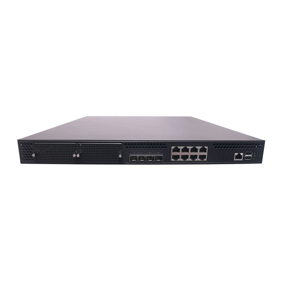
Page 16: Front Panel
NCA-4025 User Manual Front Panel Description PCIe Expansion 2 x PCIe Expansion slot (Optional) SFP Ports 4 x SFP+port RJ45 Ports 8 x 1G RJ45 port LOM Port 1 x Reserved for LOM port Console Port 1 x RJ45 console port USB Ports 2 x USB 2.0 port... -
Page 17: Rear Panel
NCA-4025 User Manual Rear Panel Description Alarm Mute Button 1 x Mute Button On/Off Switch 1 x Power Switch Cooling Fans 4 x Fans Redundant PSUs 2 x Power Supplies... -
Page 18: Block Diagram
NCA-4025 User Manual Block Diagram The block diagram indicates how data flows among components on the motherboard. Please refer to the following figure for the motherboard layout design. -
Page 19: Motherboard
NCA-4025 User Manual Motherboard Layout CONN1 JOPEN1 JPW1 FAN1 FAN2 FAN3 FAN4 PWRON1 RST1 JTAG1 PWJ1 JNGFF1 PWJ2 JCOM1 VGA1 80PORT JDB1 SATA1/2 PW11 CMOS1 JUSB1 PCI-E GEN3 x8 PCI-E GEN3 x8 PCI-E GEN3 x8 10G KR CONN SPIROM1... - Page 20 NCA-4025 User Manual Internal Jumpers and Connectors The pin headers on the motherboard are often associated with important functions. With the shunt (Jumper) pushed down on the designated pins (the pin numbers are printed on the circuit board, surrounding the pin header), certain feature can be enabled or disabled.
- Page 21 NCA-4025 User Manual JOPEN1 1x2 2.54mm CASE OPEN WAFER JPWR1 1x2 2.54mm POWER SWITCH WAFER CONN1 1x2 2.54mm BUZZER MUTE WAFER 1x4 2.54mm Power IC Programming I2C pin header DIMM1/2/3/4 DDR4 CONNECTOR Connectors Pin Assignment 1. PWJ1/PWJ2: PSU connector Pin #...
- Page 22 NCA-4025 User Manual 3. PCIE1/2/3: Gen 3 PCI Express x8 SLOT Pin # Description Pin # Description PCIE1 +12V 12V_A PRSNT1* 12V_B 12V_C 12V_D 12V_E +12V +12V GND1 GND2 SMCLK JTAG2 +12V +12V SMDAT JTAG3 GND3 JTAG4 3.3V_A JTAG5 JTAG1 3.3V_B...
- Page 23 NCA-4025 User Manual CPUPERP5 CPUPERN5 CPUPETP6 CPUPETN6 CPUPERP6 CPUPERN6 CPUPETP7 CPUPETN7 CPUPERP7 CPUPERN7 4. PCIE4: 10G KR Connector for IO-40253 or IO-CG40212 only Pin # Description Pin # Description PCIE4 +3.3V 12V_A PRSNT1* 12V_B 12V_C +3.3V 12V_D 12V_E GND1 GND2...
- Page 24 NCA-4025 User Manual KR_BCMTX_C_PRX_N2 KR_PTX_BCMRX_P3 KR_PTX_BCMRX_N3 KR_BCMTX_C_PRX_P3 KR_BCMTX_C_PRX_N3 SMB_PCH10G_SDA0 SMB_PCH10G_SCL0 SMB_PCH10G_SDA2 SMB_PCH10G_SDA1 SMB_PCH10G_SCL2 SMB_PCH10G_SCL1 INPHI_RESTL SMB_PCH10G_SDA3 SMB_PCH10G_SCL3 LED_GBE0_SPEED FM_L2_LVC3_MOD_A LED_GBE0_ACT FM_L2_LVC3_MOD_A LED_GBE1_SPEED FM_L2_LVC3_MOD_A LED_GBE1_ACT FM_L2_LVC3_MOD_A LED_GBE2_SPEED LED_GBE2_ACT LED_GBE3_SPEED LED_GBE3_ACT 5. SATA1/SATA2: SATA Connector Pin # Description...
- Page 25 NCA-4025 User Manual 6. JSPIROM1: 2x7 2.0mm SPI ROM programming & TPM module pin header Pin # Description Pin # Description JSPIROM1 3.3V ME POWER SPI_CS1# SPI_CS0# 3.3V ME POWER SPI_MISO_TPM SPI_PCH_IO3 SPI_CLK_TPM 2X7P_N12 SPI_MOSI_TPM IRQ_TPM_SPI#_R SPI_TPM_CS0# RESET 7. CMOS1: 1x3 2.54mm pin header Clear CMOS Data...
- Page 26 NCA-4025 User Manual 11. JUSB1: 2x5 2.54mm DUAL PORT USB 2.0 Box Header Pin # Description Pin # Description +5V_SB +5V_SB USB3- USB4- USB3+ USB4+ 12. JCOM1: 2x5 2.0mm Serial Port2 Pin Header Description JCOM1 Pin# RS-232 Data Carrier Detect (DCDB #)
- Page 27 NCA-4025 User Manual BMC_UART1_RTS BMC_UART1_DTR BMC_UART1_TX BMC_UART1_RX BMC_UART1_DSR# BMC_UART1_CTS# 15. JRST1: HW/SW rest setting jumper (Default: HW Reset) Pin # Description 1-2 (Default ) Hardware Reset Software Reset 16. PWRON1: 1x2 2.54mm EE Debug Force PSU ON pin header (default: Keep Open, No Jumper On pin1 &...
- Page 28 NCA-4025 User Manual Pin#1 Pin#2 Pin#3 Pin#4 Pin#5 FAN1 FAN1 BMC_PWMOUT1 BMC_FAN_TECH_IN1 BMC_FAN_TECH_IN2 FAN2 BMC_PWMOUT1 BMC_FAN_TECH_IN3 BMC_FAN_TECH_IN4 FAN3 BMC_PWMOUT1 BMC_FAN_TECH_IN5 BMC_FAN_TECH_IN6 FAN4 BMC_PWMOUT1 BMC_FAN_TECH_IN7 BMC_FAN_TECH_IN8 19. JOPEN1: 1x2 2.54mm CASE OPEN WAFER Pin # Description JOPEN1 Ground INTRUDER# 20. JPWR1: 1x2 2.54mm POWER SWITCH WAFER...
-
Page 29: Chapter 2: Hardware Setup
NCA-4025 User Manual CHAPTER 2: HARDWARE SETUP To reduce the risk of personal injury, electric shock, or damage to the system, please remove all power connections to shut down the device completely. Also, please wear ESD protection gloves when conducting the steps in this chapter. - Page 30 NCA-4025 User Manual Memory Module Installation Instructions Please follow the steps below to install the DIMM memory modules. Memory Memory 1. Power off the system. 2. Locate the memory module. 3. Pull open the DIMM slot latches. 4. Align the notch of the module with the socket key in the slot and carefully insert the card into the slot.
-
Page 31: Installing M.2 Modules
NCA-4025 User Manual Installing M.2 Modules This system supports two M.2 module slots that can accommodate various module sizes. 1x M.2-3042, B key or B+M Key (Optional) via PCIEx1/USB3.0/SATA3 interface. 1x M.2-3042/3080/30110, B key or B+M key (Optional) via PCIEx1/USB3.0/SATA3 interface To install the M.2 module... -
Page 32: Installing The Tpm Module
NCA-4025 User Manual Installing the TPM Module 1. Locate the SPIROM1 connector on the motherboard. 2. Insert the TPM module. It is important the PIN1 marked on the connector is inserted into the corresponding pin hole in the module. PIN 1... - Page 33 NCA-4025 User Manual Installing the Hard Disk This system supports two 2.5” HDD/SSD with a disk tray. 1. The disk tray is already secured on the bottom panel. Loosen the screw that secures it and slide the tray in the direction shown in the picture to remove it.
- Page 34 NCA-4025 User Manual 3. Mount the disk onto the tray and secure it with the provided disk screws. Make sure SATA connector faces the direction shown SATA Connector in the picture. 4. Secure the tray on the bottom panel with the provided screw.
-
Page 35: Replacing The Cooling Fans
NCA-4025 User Manual Replacing the Cooling Fans Cooling fans may wear down eventually. Please refer to the steps below for replacing cooling fans. When using a new cooling fan, just reverse the steps to install the fan back onto the enclosure and the system. -
Page 36: Installing The Ac Power Supply
NCA-4025 User Manual Installing the AC Power Supply Power supply units wear down eventually. Please be noted that this system supports only 450W PSU. Please prepare the power supply units matching this capacity. 1. On the rear panel, locate the power supply units and disconnect the power cords. -
Page 37: Mounting The System
NCA-4025 User Manual Mounting the System There are two methods for installing this system into a rack: With Mounting Ear Brackets only This method is quick and easy by fixing this system to the front posts of the rack, but it also makes servicing the system more difficult. - Page 38 NCA-4025 User Manual Installing the System Using Mounting Ear Brackets Only 1. Check the accessory pack for the following items: 1x Screw Pack 2x Ear Brackets 2. Align the bracket to the side of the chassis and make sure the screw-holes are matched, and then secure the bracket onto the chassis with three provided screws.
- Page 39 NCA-4025 User Manual Installing the System Using the Slide Rail Kit (with Mounting Ear Brackets) 1. Check the package contents of the Slide Rail Kit. The kit shall include the following items: 1x pack of M4X4L screws (for securing the Rail Brackets on the system) 1x pack of 7.1 Round Hole...
- Page 40 NCA-4025 User Manual 5. Align the bracket to the side of the chassis and make sure the screw- holes are matched, and then secure the bracket onto the chassis with three provided M4X4L screws. Align the screws with the holes indicated on the brackets and the screw holes on the side of the chassis.
- Page 41 NCA-4025 User Manual 9. For the rear rack installation, slide the rail to aim and engage the bolts on the rail’s rear end with the two available holes on the post, and the rail assembly will click into place. Clic 10.
- Page 42 NCA-4025 User Manual 12. While pushing in the system, also push and hold the Rail Lock tab on both brackets. Rail Lock Push the system all the way in until it stops. To remove the system from the rack, gently pull it outwards while pushing the Release Tab on both sides of the brackets.
-
Page 43: Chapter 3: Software Setup
CHAPTER 3: SOFTWARE SETUP BIOS Setup BIOS is a firmware embedded on an exclusive chip on the system’s motherboard. Lanner's BIOS firmware offering including market-proven technologies such as Secure Boot and Intel Boot Guard technology deliver solid commitments for the shield protection against malware, uncertified sequences and other named cyber threats. - Page 44 NCA-4025 User Manual Setup main page contains BIOS information and project version information. Feature Description BIOS Vendor: American Megatrends Core Version: AMI Kernel version, CRB code base, X64 Compliancy: UEFI version, PI version BIOS Information Project Version: BIOS release version...
- Page 45 NCA-4025 User Manual Advanced Page Select the Advanced menu item from the BIOS setup screen to enter the “Advanced” setup screen. Users can select any of the items in the left frame of the screen.
- Page 46 NCA-4025 User Manual Trusted Computing Feature Options Description Enables or disables BIOS support for security device. By Security Device Enabled disabling this function, OS will not show Security Support Disabled Device. TCG EFI protocol and INT1A interface will not be available.
- Page 47 NCA-4025 User Manual Trusted Computing (TPM1.2) Feature Options Description Enables or disables BIOS support for security device. By Security Device Enabled disabling this function, OS will not show Security Support Disabled Device. TCG EFI protocol and INT1A interface will not be available.
- Page 48 NCA-4025 User Manual Trusted Computing (TPM2.0)
- Page 49 NCA-4025 User Manual Feature Options Description Enables or disables BIOS support for security device. By Security Device Enabled disabling this function, OS will not show Security Support Disabled Device. TCG EFI protocol and INT1A interface will not be available. Enabled SHA-1 PCR Bank Enables or disables SHA-1 PCR Bank.
- Page 50 NCA-4025 User Manual Super IO Configuration...
- Page 51 NCA-4025 User Manual Serial port 1 Configuration Feature Options Description Enabled Serial Port Enable or Disable Serial Port (COM) Disabled Device Settings IO=3F8h; IRQ = 4...
- Page 52 NCA-4025 User Manual Serial port 2 Configuration Feature Options Description Enabled Serial Port Enable or Disable Serial Port (COM) Disabled Device Settings IO=2F8h; IRQ = 3...
- Page 53 NCA-4025 User Manual Case Open Configuration Feature Options Description Enabled Case Open Enables or disables Case Open function Disabled...
- Page 54 NCA-4025 User Manual Digital I/O Configuration Feature Options Description Output Low Digital I/O Output 1 Configure Digital I/O Pin1 Output High Output Low Digital I/O Output 2 Configure Digital I/O Pin3 Output High Output Low Digital I/O Output 3 Configure Digital I/O Pin5...
- Page 55 NCA-4025 User Manual Watch Dog Timer Configuration Feature Options Description Watch Dog Enabled Enables or disables Watch Dog Timer function Timer Disabled...
- Page 56 NCA-4025 User Manual Status LED Configuration Feature Options Description Status LED GREEN Configures Status LED color...
- Page 57 NCA-4025 User Manual Serial Port Console Redirection Feature Options Description COM0 Enabled Console Enables or disables Console Redirection Disabled Redirection...
- Page 58 NCA-4025 User Manual Console Redirection Settings Feature Options Description VT100: ASCII char set VT100 VT100+:Extends VT100 to support color, function VT100+ keys, etc. Terminal Type VT-UTF8 VT-UTF8:Uses UTF8 encoding to map Unicode ANSI chars onto 1 or more bytes ANSI: Extended ASCII char set...
- Page 59 NCA-4025 User Manual RTS/CTS VT-UTF8 Combo Key Disabled Enables VT-UTF8 Combination Key Support for Support Enabled ANSI/VT100 terminals Disabled With this mode enabled, only text will be sent. This Recorder Mode Enabled is to capture Terminal data. Disabled Resolution 100x31...
- Page 60 NCA-4025 User Manual PCI Subsystem Settings Feature Options Description Enables or Disables 64bit capable Devices to be Above 4G Disabled Decoded in Above 4G Address Space (Only if System Decoding Enabled Supports 64 bit PCI Decoding). If the system has SR-IOV capable PCIe Devices, this...
- Page 61 NCA-4025 User Manual USB Configuration Feature Options Description Enables Legacy USB support. Enabled Auto option disables legacy support if no Legacy USB Support Disabled USB devices are connected; Auto Disabled option will keep USB devices available only for EFI applications.
- Page 62 NCA-4025 User Manual 5 sec command time-out 10 sec 20 sec Maximum time the device will take before it properly reports itself to the Host Auto Device power-up delay Controller. Auto uses default value: for a Manual Root port, it is 100 ms, for a Hub port the...
- Page 63 NCA-4025 User Manual Network Stack Configuration Feature Options Description Disabled Network Stack Enables or disables UEFI Network Stack Enabled Disabled Enables Ipv4 PXE Boot Support. If IPV4 is disabled, Ipv4 PXE Support Enabled PXE boot option will not be created.
- Page 64 NCA-4025 User Manual CSM Configuration Feature Options Description Disabled CSM Support Enables or disables CSM Support Enabled Do Not Launch Controls the execution of UEFI and Legacy Network UEFI PXE OpROM Legacy Do Not Launch Controls the execution of UEFI and Legacy...
- Page 65 NCA-4025 User Manual Control Legacy PXE Boot Feature Options Description Control Legacy PXE Disabled Control Legacy PXE Boot from which LAN Boot from MGT Lan1...
- Page 66 NCA-4025 User Manual Platform Configuration Page Select the Platform menu item from the BIOS setup screen to enter the Platform Setup screen. Users can select any of the items in the left frame of the screen. Feature Options Description Displays and provides option to change...
- Page 67 NCA-4025 User Manual PCH Configuration Feature Options Description PCI Express None PCI Express Configuration settings Configuration PCH SATA None SATA devices and settings Configuration PCH sSATA None sSATA devices and settings Configuration Security Configuration None Security Configuration settings Power ON...
- Page 68 NCA-4025 User Manual PCI Express Configuration Feature Options Description Enable PCIe root port function swapping PCIe Root Port Disabled feature to dynamically assign function 0 Function Swapping Enabled to enabled root port. MRRS 128B MRRS 256B MRRS 512B Max Read Request Size PCIE Max Read Request Size Selection.
- Page 69 NCA-4025 User Manual PCH sSATA Configuration Feature Options Description Disabled sSATA Controller Enables or disables sSATA Controller Enabled AHCI This will configure sSATA as RAID or Configure SATA as RAID AHCI. Support Aggressive Disabled Link Power Enables or disables SALP...
- Page 70 NCA-4025 User Manual up at boot. Otherwise all drives spin up at boot. Hard Disk Drive Identify the SATA port is connected to SATA Device Type Solid State Drive Solid State Drive or Hard Disk Drive Unknown ISATA Identify the SATA Topology if it is Default...
- Page 71 NCA-4025 User Manual Security Configuration Feature Options Description SMM BIOS Write Disabled Enable/Disable SMM BIOS Write-Protect feature Protect Enabled...
- Page 72 NCA-4025 User Manual Server ME Configuration...
- Page 73 NCA-4025 User Manual Runtime Error Logging Feature Options Description Disabled System Error Enable/Disable setup options. System Errors Enabled...
- Page 74 NCA-4025 User Manual Socket Configuration Page Select the Socket menu item from the BIOS setup screen to enter the Socket Setup screen. Users can select any of the items in the left frame of the screen. Feature Options Description Processor...
- Page 75 NCA-4025 User Manual Processor Configuration...
- Page 76 NCA-4025 User Manual Feature Options Description Hyper-Threading Disabled Enables Hyper Threading (Software Method to [ALL] Enabled Enable/Disable Logical Processor threads. Disabled Machine Check Enable or Disable the Machine Check Enabled Execute Disable Disabled When disabled, it forces the XD feature flag to Enabled always return 0.
- Page 77 NCA-4025 User Manual Per-Socket Configuration Feature Options Description CPU Socket0 None None Configuration...
- Page 78 NCA-4025 User Manual CPU Socket0 Configuration Feature Options Description Core Disable 0: Enable all cores. 3fff: Disable all cores Bitmap(Hex) Disabled IOT Cfg None Enabled...
- Page 79 NCA-4025 User Manual Memory Configuration Feature Options Description Auto 1000 1066 1200 1333 1400 1600 1800 1866 Memory 2000 Maximum Memory Frequency Selections in Mhz. Frequency 2133 Do not select Reserved 2200 2400 2600 2666 2800-OvrClk 2933-OvrClk 3000-OvrClk 3200-OvrClk 3400-OvrClk...
- Page 80 NCA-4025 User Manual 3733-OvrClk 3800-OvrClk 4000-OvrClk 4200-OvrClk 4266-OvrClk 4400-OvrClk Memory Displays memory topology with Dimm population None Topology information...
- Page 81 NCA-4025 User Manual IIO Configuration Feature Options Description Socket0 None None Configuration IOAT Configuration None All IOAT configuration options Intel® VT for Press <Enter> to bring up the Intel? VT for None Directed I/O (VT-d) Directed I/O (VT-d) Configuration menu.
- Page 82 Socket0 Configuration Feature Options Description Socket 0 None Settings related to PCI Express Port 1A PcieBr1D00F0 Socket 0 None Settings related to PCI Express Port 1C PcieBr1D02F0 Socket 0 None Settings related to PCI Express Port 2A PcieBr2D00F0 Socket 0 None Settings related to PCI Express Port 2C PcieBr2D02F0...
- Page 83 NCA-4025 User Manual IOAT Configuration Feature Options Description Sck0 IOAT Config None None Disable TPH TLP Processing Hint disable Disabled Prioritize TPH Prioritize TPH Enabled Disabled Relaxed Ordering Relaxed Ordering Enable/Disable Enabled...
- Page 84 Intel® VT for Directed I/O (VT-d) Feature Options Description Intel® VT for Disabled Press <Enter> to bring up the Intel? VT for Directed I/O (VT-d) Enabled Directed I/O (VT-d) Configuration menu. Interrupt Disabled Enable/Disable VT_D Interrupt Remapping Remapping Enabled Support Disabled Enable/Disable Non-Isoch VT_D Engine Pass PassThrough DMA...
- Page 85 NCA-4025 User Manual Advanced Power Management Configuration Feature Options Description P State Control Configuration Sub Menu, CPU P State Control None include Turbo, XE and etc. CPU C State Control None CPU C State setting...
- Page 86 CPU P State Control Feature Options Description Disabled SpeedStep(Pstates) Enables or disables EIST (P-States) Enabled Max Performance Boot performance Max Efficient Select the performance state that the mode Set by Intel Node BIOS will set before OS hand off. Manager Disabled Energy Efficient Turbo Disable, MSR Energy Efficient Turbo...
- Page 87 NCA-4025 User Manual CPU C State Control Feature Options Description Autonomous Core C- Disabled Autonomous Core C-State Control State Enabled Disabled Enables or disables CPU C6(ACPI C3) CPU C6 report Enabled report to OS Enhanced Halt State Disabled Core C1E auto promotion Control. Takes...
- Page 88 Security Page Select the Security menu item from the BIOS setup screen to enter the Security Setup screen. Users can select any of the items in the left frame of the screen. Feature Description If ONLY the Administrator's password is set, it only limits access to Setup and is only asked for when entering Administrator Password Setup.
- Page 89 NCA-4025 User Manual Secure Boot Feature Options Description Secure Boot is activated when Platform Key(PK) is Secure Boot Disabled enrolled, System mode is User/Deployed, and CSM Enable Enabled function is disabled. Customizable Secure Boot mode: In Custom mode, Secure Boot...
- Page 90 Key Management Feature Options Description Factory Key Disabled Provision factory default keys on next re-boot only Provision Enabled when System in Setup Mode. Force System to User Mode. Configure NVRAM to Restore Factory None contain OEM-defined factory default Secure Boot keys keys.
- Page 91 NCA-4025 User Manual Boot Page Select the Boot menu item from the BIOS setup screen to enter the Boot Setup screen. Users can select any of the items in the left frame of the screen. Feature Options Description The number of seconds to wait for setup Setup Prompt Timeout activation key.
- Page 92 NCA-4025 User Manual Save and Exit Page Select the Save and Exit menu item from the BIOS setup screen to enter the Save and Exit Setup screen. Users can select any of the items in the left frame of the screen.
- Page 93 NCA-4025 User Manual ■ Restore Defaults Restore default values for all setup options. Select “Yes” to load Optimized defaults. Note The items under Boot Override were not same with image. It should depend on devices connect on system.
-
Page 94: Appendix A: Led Indicator Explanations
NCA-4025 User Manual APPENDIX A: LED INDICATOR EXPLANATIONS The status explanations of LED indicators on Front Panel are as follows: System Power System Status System Power Solid Green The system is powered on The system is powered off System Status This LED indicator is programmable. -
Page 95: Appendix B: Dual Bios Introduction
Eventually, you are left with no choice but to ship the board back to the manufacturer. Lanner understands this pain and has empowered our products with the Dual BIOS feature. Normally, the Primary BIOS is used to boot the OS during powering up; when Primary BIOS is down, the Recovery BIOS automatically jumps in to boot up the OS for the User to take further steps such as performing data backup and BIOS upgrade. - Page 96 NCA-4025 User Manual Addressing BIOS Start-up Failure with Dual BIOS Few things can shut down a computer as completely as a corrupted BIOS. With Dual BIOS feature, you will be guaranteed to enter a healthy OS to perform thorough troubleshooting before the situation is irreparable.
-
Page 97: Appendix C: Redundant Power Module Behavior
NCA-4025 User Manual APPENDIX C: REDUNDANT POWER MODULE BEHAVIOR Define the Alarm and Mute behavior Power Module Power Module Power Cord Fail Remove Remove Buzzer Alarm Alarm Alarm Change back the Good Put back the PSU Module Plug-in the Power cord... -
Page 98: Appendix D: Fan Sequence
NCA-4025 User Manual APPENDIX D: FAN SEQUENCE Define the sequence of the FAN FAN Sequence The detection is from the left to the right side , from the bottom to the top side Example:... - Page 99 NCA-4025 User Manual APPENDIX E: SMART POWER AND RESET BUTTON Smart Power and Reset Button – Control by CPLD...
- Page 100 NCA-4025 User Manual APPENDIX F: TERMS AND CONDITIONS Warranty Policy 1. All products are under warranty against defects in materials and workmanship for a period of one year from the date of purchase. 2. The buyer will bear the return freight charges for goods returned for repair within the warranty period;...
- Page 101 NCA-4025 User Manual RMA Service Request Form When requesting RMA service, please fill out the following form. Without this form enclosed, your RMA cannot be processed.
Need help?
Do you have a question about the NCA-4025 and is the answer not in the manual?
Questions and answers