Advertisement
Quick Links
Advertisement

Subscribe to Our Youtube Channel
Related Manuals for Lanner NCA-1040SE


Summary of Contents for Lanner NCA-1040SE
- Page 1 Network Appliance Platforms NCA-1040SE User Manual Version: 1.1 Date of Release: 2023-06-21...
- Page 2 - assumed to be qualified in the servicing of computer equipment, such as professional system integrators, or service personnel and technicians. The latest version of this document can be found on Lanner’s official website, available either through the product page or through the Lanner Download Center page with a login account and password.
- Page 3 NCA-1040SE User Manual Taiwan Corporate Headquarters China Lanner Electronics Inc. Beijing L&S Lancom Platform Tech. Co., Ltd. 7F, No.173, Sec.2, Datong Rd. Guodong LOFT 9 Layer No. 9 Huinan Road, Xizhi District, New Taipei City 22184, Huilongguan Town, Changping District, Beijing...
- Page 4 NCA-1040SE User Manual Intel® and Intel® Celeron® are trademarks of Intel Corporation or its subsidiaries in the U.S. and/or other countries. Microsoft Windows and MS-DOS are registered trademarks of Microsoft Corp. All other product names or trademarks are properties of their respective owners.
- Page 5 NCA-1040SE User Manual Ne portez pas de vêtements amples ou de bijoux qui pourraient être pris dans le châssis. Attachez votre cravate ou écharpe et remontez vos manches. Portez des lunettes de sécurité pour protéger vos yeux. N’effectuez aucune action qui pourrait créer un danger pour d’autres ou rendre l’équipement dangereux.
- Page 6 The installation of this product must be performed by trained specialists; otherwise, a non-specialist might create the risk of the system’s falling to the ground or other damages. Lanner Electronics Inc. shall not be held liable for any losses resulting from insufficient strength for supporting the system or use of inappropriate installation components.
- Page 7 NCA-1040SE User Manual Before turning on the device, ground the grounding cable of the equipment. Proper grounding (grounding) is very important to protect the equipment against the harmful effects of external noise and to reduce the risk of electrocution in the event of a lightning strike. To uninstall the equipment, disconnect the ground wire after turning off the power. A ground wire (green-and-yellow) is required and the part connecting the conductor must be greater than 4 mm2 or 10 AWG.
- Page 8 NCA-1040SE User Manual Package Content ..........................10 Ordering Information ........................10 Optional Accessories ........................10 System Specifications ........................11 Front Panel ............................. 12 Rear Panel ............................13 Jumpers and Connectors ........................ 14 Opening the Chassis ........................22 Installing the System Memory ....................... 23 Installing M.2 Storage Card (Optional) ...................
- Page 9 NCA-1040SE User Manual Warranty Policy ..........................57...
- Page 10 NCA-1040SE User Manual NCA-1040SE is a compact desktop appliance empowered by Intel® Atom® x6413E / Intel® Celeron® N6210 (codenamed Elkhart lake). The NCA-1040SE’s form factor, relatively low power consumption, robust processing capability, up to 32GB DDR4 3200MHz SODIMM and its various I/O ports together make it ideal for edge deployments, branch offices and retail settings.
- Page 11 NCA-1040SE User Manual Form Factor Fanless Desktop SKU A: Intel® Atom® X6413E (Elkhart Lake) Processor Options SKU C: Intel® Celeron® N6210 (Elkhart Lake) Platform Frequency 1.5GHz/1.2GHz CPU Cores 4 / 2 Chipset BIOS AMI SPI Flash BIOS Technology DDR4 3200MT/s SO-DIMM System Memory Max.
- Page 12 NCA-1040SE User Manual Description Antennas 2x SMA Antenna Holes (SKU A Only) Reset Button 1x Reset Button LED Indicators Power/Status/Storage/M.2/Mini-PCIe, refer to Appendix A Console Port 1x RJ45 Console Port USB Port 1x USB 3.0 Port SKU A Only: 4x Antenna holes for Wi-Fi/LTE/5G...
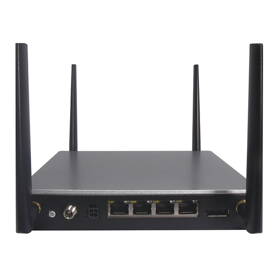
- Page 13 NCA-1040SE User Manual Description Antennas 2x SMA Antenna Holes (SKU A Only) Power Button 1x Power Button with LED Power Inlet 1x DC Jack with Lock PoE+ (PSE) Port 1x 4-pin 54V Input Port with Lock (ATX4P) for PoE+ (Optional, SKU A Only) LAN Ports 4x 2.5GbE RJ45 Ethernet Ports with LED...
- Page 14 NCA-1040SE User Manual The following displays the connectors and jumpers on the motherboard layout.
- Page 15 NCA-1040SE User Manual The following references the pin assignments and internal connectors of NCA-1040SE. JCOMS1: RTC Reset Description Clear RTC_TEST Clear RTC_RST J8: Reset Option Description Hardware Reset 2-3 (Default) Software Reset PW2: Power Supply Connector of PSE Description +P54V +P54V JPW1: SATA Power Connector 1x4 Pins 2.54mm...
- Page 16 NCA-1040SE User Manual COM1: RJ45 Console Description Request to Send (RTS) Transmitted Data (TxD) Signal Ground Signal Ground Received Data (RxD) Clear to Send (CTS) USB1: USB 3.0 single CONN Description +P5V_USB1 USB20_N1 USB20_P1 USB30_RXN0 USB30_RXP0 USB30_TXN0 USB30_TXP0 DP1: Display Port 20P 0.6mm...
- Page 17 NCA-1040SE User Manual SIM1/2: Nano SIM push-push Description UIMx_PWR UIMx_RST# UIMx_CLK UIMx_DETECT UIMx_DAT SATA1:180° SATA Connector Description PCIE1: MiniPCIe Socket Description Description NC, PMC_WAKE# +P3V3_S +P1V5_S NC, SMB_CLK PCIE_TXN +P1V5_S NC, SMB_DATA PCIE_CLKREQ5# PCIE_TXP USB20_N0 REFCLK- USB20_P0 REFCLK+ +P3V3_S +P3V3_S...
-
Page 18: Pin Description
NCA-1040SE User Manual LED_WLAN_N PH, +P3V3_S MPCIE_RST# +P1V5_S PCIE_RXN +P3V3_S PCIE_RXP +P3V3_S M2_1: M.2 B-Key for Storage Description Description +P3V3_S +P3V3_S B-KEY B-KEY B-KEY B-KEY B-KEY B-KEY B-KEY B-KEY SATA_C_RXP0 SATA_C_RXN0 SATA_C_TXN0 SATA_C_TXP0... - Page 19 NCA-1040SE User Manual +P3V3_S +P3V3_S +P3V3_S M2_B_KEY1: M.2 B-Key for 4G/5G Description Description +P3V3_A +P3V3_A PH ,+P1V8_A USB2_DP0 PH, +P3V3_A USB2_DN0 LED_M2_WWAN_N B-KEY B-KEY B-KEY B-KEY B-KEY B-KEY B-KEY B-KEY PH ,+P1V8_A PH, +P3V3_A NC, WAKE_UP# PH, +P3V3_A M2_USB30_TXN2 UIM1_RST#...
- Page 20 NCA-1040SE User Manual M2_PCIE_TXN1 UIM2_PWR M2_PCIE_TXP1 NC, PCIE_B_RST# M2_PCIE_CLKREQ1# M2_PCIE_CLKN NC, B_WAKE# M2_PCIE_CLKP UIM1_DETECT NC, M2_RESET# +P3V3_A +P3V3_A +P3V3_A JFAN1: DIP 2.54mm 5-Pin Fan Connector Description JUSBDOM1: DIP 2.54mm 2x5 Box Header R/A Type Description +P5V_USB2 USB20_L_N USB20_L_P NC,USB_R_WP...
- Page 21 NCA-1040SE User Manual JDI01: DIP 2.0mm 2x3 Pin Header Description DIO_GPI_1 DIO_GPO_1 DIO_GPI_2 DIO_GPO_2 JSPI1: SMD 2.0mm 2x5 Pin Header Description Description SPI0_IO3_HOLD# SPI0_CS0_R# V_3P3_SPI SPI0_IO1_MISO_R SPI0_CLK_R SPI0_IO0_MOSI_R J2: DIP 2.43mm 1x3 Pin Header for VCCIN debug Description SMB_DATA_VR SMB_CLK_VR...
- Page 22 NCA-1040SE User Manual To reduce the risk of personal injury, electric shock, or damage to the system, please remove all power connections to shut down the device completely and wear ESD protection gloves when handling the installation steps. 1. Power off the system and remove all power connections.
- Page 23 NCA-1040SE User Manual The motherboard supports a DIMM DDR4 3200MHz non-ECC up to 32GB, which is located on the bottom side of the motherboard. Please follow the steps below to install the DIMM memory module properly. 1. Power off the system.
- Page 24 NCA-1040SE User Manual The system supports one M.2 slot for additional data storage (SSD is recommended due to heat and vibration concerns). Please follow the steps for installation. 1. Power off the system and open the chassis cover. 2. Locate the M.2 slot on the motherboard.
- Page 25 NCA-1040SE User Manual The motherboard provides one M.2 slot for LTE/5G module card. Please follow the procedures for installation. LTE module requires two antennas, and 5G module requires four antennas. 1. Power off the system and open the chassis cover.
- Page 26 NCA-1040SE User Manual Installing 5G Antennas Front Panel Rear Panel Locate the four (4) antenna RF cables. Locate the four (4) IPEX connectors on the 5G module card. Connect RF cables to the 5G module card.
- Page 27 NCA-1040SE User Manual Screw on the four (4) antennas to the system.
- Page 28 NCA-1040SE User Manual The system supports one mini-PCIe slot for a Wi-Fi or BT module card. Please follow the steps to install the Wi-Fi module card. Wi-Fi module requires two antennas. 1. Power off the system and open the chassis cover.
- Page 29 NCA-1040SE User Manual Installing Wi-Fi Antennas Rear Panel Locate the two (2) antenna RF cables. Locate the two (2) IPEX connectors on the Wi-Fi module card Connect the RF cables to the Wi-Fi module card. Screw on the two (2) antennas to...
- Page 30 NCA-1040SE User Manual The SIM slot on the bottom panel supports the LTE/5G module card. Please follow the steps below for SIM card placement. 1. Power off the system. 2. Turn the system upside down, with its bottom side facing up.
- Page 31 BIOS (Basic Input / Output System) is the program that controls the computer boot process. BIOS is a firmware embedded on an exclusive chip on the system’s motherboard. Lanner's BIOS firmware offering including market-proven technologies such as Secure Boot and Intel Boot Guard technology deliver solid commitments for the shield protection against malware, uncertified sequences and other named cyber threats.
- Page 32 NCA-1040SE User Manual Setup main page contains BIOS information and project version information. Feature Description BIOS Vendor: American Megatrends Core Version: AMI Kernel version, CRB code base, X64 Compliancy: UEFI version, PI version BIOS Information Project Version: BIOS release version...
- Page 33 NCA-1040SE User Manual Select the Advanced menu item from the BIOS setup screen to enter the “Advanced” setup screen. Users can select any of the items in the left frame of the screen.
- Page 34 NCA-1040SE User Manual Feature Options Description Hardware Enabled To turn ON/OFF the MLC streamer prefetcher Prefetcher Disabled Adjacent Cache Enabled To turn ON/OFF prefetching of adjacent cache lines. Line Prefetch Disabled Intel (VMX) Enabled Intel (VMX) Virtualization Technology Virtualization Technology...
- Page 35 NCA-1040SE User Manual Feature Options Description Max Battery Boot Performance Select the performance state that the BIOS will set Mode Non-Turbo Performance starting from reset vector. Turbo Performance Enabled Allows more than two frequency ranges to be Intel® SpeedStep™ Disabled supported.
- Page 36 NCA-1040SE User Manual Feature Options Description Me FW Image Enabled Enable/Disable ME FW Update function. Re-Flash Disabled...
- Page 37 NCA-1040SE User Manual Feature Options Description Enables or disables BIOS support for security device. By Security Device Enabled disabling this function, OS will not show Security Device. TCG Support Disabled EFI protocol and INT1A interface will not be available. Enabled SHA-1 PCR Bank Enables or disables SHA-1 PCR Bank.
- Page 38 NCA-1040SE User Manual Feature Options Description Disabled LAN1 Control Legacy PXE LAN2 Control PXE Boot from which LAN. Boot From LAN3 LAN4...
- Page 39 NCA-1040SE User Manual Feature Options Description Enabled Serial Port Enables or Disables Serial Port 1 Disabled Device Settings IO=3F8h; IRQ=4...
- Page 40 NCA-1040SE User Manual...
- Page 41 NCA-1040SE User Manual Feature Options Description Enabled Console Redirection Enables or Disables Console Redirection Disabled...
- Page 42 NCA-1040SE User Manual Feature Options Description VT100 VT100: ASCII char set VT100+ VT100+: Extends VT100 to support color, function keys, etc. Terminal Type VT-UTF8 VT-UTF8: Uses UTF8 encoding to map Unicode chars onto 1 ANSI or more bytes 9600 19200 Selects serial port transmission speed.
- Page 43 NCA-1040SE User Manual None Flow Control Hardware Flow Control can prevent data loss from buffer overflow. RTS/CTS VT-UTF8 Combo Disabled Enables VT-UTF8 Combination Key Support for ANSI/VT100 Key Support Enabled terminals Disabled With this mode enabled, only text will be sent. This is to...
- Page 44 NCA-1040SE User Manual Feature Options Description Disabled If the system has SR-IOV capable PCIe Devices, this option SR-IOV Support Enabled enables or disables Single Root IO Virtualization Support.
- Page 45 NCA-1040SE User Manual Feature Options Description Enabled Enables Legacy USB support. Legacy USB Disabled Auto option disables legacy support if no USB devices are connected; Support Auto Disabled option will keep USB devices available only for EFI applications Enabled This is a workaround for OSes without XHCI hand-off support. The XHCI...
- Page 46 NCA-1040SE User Manual Feature Options Description Disabled Network Stack Enables or disables UEFI Network Stack Enabled Disabled Enables IPv4 PXE Boot Support. If IPv4 is disabled, PXE boot IPv4 PXE Support Enabled option will not be created. Disabled Enables IPv4 HTTP Boot Support. If IPv4 is disabled, HTTP...
- Page 47 NCA-1040SE User Manual...
- Page 48 NCA-1040SE User Manual Feature Options Description Disable VT-d capability. VT-d Enable Option to Enable/Disable VT-d. X2APIC Disable Enable/Disable X2APIC_OPT_OUT Opt Out Enable...
- Page 49 NCA-1040SE User Manual Feature Options Description Disabled SATA Controller(s) Enables/Disables SATA controller Enabled SATA Mode AHCI SATA mode support. Selection...
- Page 50 NCA-1040SE User Manual Select the Security menu item from the BIOS setup screen to enter the Security Setup screen. Users can select any of the items in the left frame of the screen. Feature Description If ONLY the Administrator’s password is set, it only limits access Administrator Password to Setup and is only asked for when entering Setup.
- Page 51 NCA-1040SE User Manual Feature Options Description Secure Boot is activated when Platform Key (PK) is Disabled Secure Boot enrolled, System mode is User/Deployed, and CSM Enabled function is disabled. Customizable Secure Boot mode: In Custom mode, Secure Boot Standard Secure Boot Policy variables can be configured by a...
- Page 52 NCA-1040SE User Manual Feature Options Description Factory Key Disabled Provision factory default keys on next re-boot only when Provision Enabled System in Setup Mode. Force System to User Mode. Configure NVRAM to contain Restore Factory Keys None OEM-defined factory default Secure Boot keys.
- Page 53 NCA-1040SE User Manual Select the Boot menu item from the BIOS setup screen to enter the Boot Setup screen. Users can select any of the items in the left frame of the screen. Feature Options Description Setup Prompt The number of seconds to wait for setup activation key.
- Page 54 NCA-1040SE User Manual Select the Save and Exit menu item from the BIOS setup screen to enter the Save and Exit Setup screen. Users can select any of the items in the left frame of the screen. ■ Save Changes and Rest When Users have completed the system configuration changes, select this option to save the changes and exit from BIOS Setup in order for the new system configuration parameters to take effect.
- Page 55 NCA-1040SE User Manual ■ Restore Defaults Restore default values for all setup options. Select “Yes” to load Optimized defaults. Note: The items under Boot Override may not have the same image. It would depend on the devices connected to the system.
-
Page 56: Appendix A: Led Indicator Explanations
NCA-1040SE User Manual APPENDIX A: LED INDICATOR EXPLANATIONS Power / Status / Storage / M.2 / mPCIe LED COLOR LED ACTION DESCRIPTION Green Steady System is powered ON Power System is powered OFF Green Steady System is Active Steady System Error... -
Page 57: Terms And Conditions
NCA-1040SE User Manual TERMS AND CONDITIONS 1. All products are under warranty against defects in materials and workmanship for a period of one year from the date of purchase. 2. The buyer will bear the return freight charges for goods returned for repair within the warranty period;... - Page 58 NCA-1040SE User Manual When requesting RMA service, please fill out the following form. Without this form enclosed, your RMA cannot be processed.
Need help?
Do you have a question about the NCA-1040SE and is the answer not in the manual?
Questions and answers