
Subscribe to Our Youtube Channel
Related Manuals for Lanner NCA-2523


Summary of Contents for Lanner NCA-2523
- Page 1 Network Computing Innovative Platforms for Next Generation Network Infrastructure NCA-2523 User Manual Version: 1.0 Date of Release: 2023-12-04...
- Page 2 - assumed to be qualified in the servicing of computer equipment, such as professional system integrators, or service personnel and technicians. The latest version of this document can be found on Lanner’s official website, available either through the product page or through the Lanner Download Center page with a login account and password.
- Page 3 NCA-2523 User Manual Contact Information Taiwan Corporate Headquarters China Lanner Electronics Inc. Beijing L&S Lancom Platform Tech. Co., Ltd. 7F, No.173, Sec.2, Datong Rd. Guodong LOFT 9 Layer No. 9 Huinan Road, Xizhi District, New Taipei City 22184, Huilongguan Town, Changping District, Beijing...
- Page 4 NCA-2523 User Manual Copyright and Trademarks This document is copyrighted © 2023. All rights are reserved. The original manufacturer reserves the right to make improvements to the products described in this manual at any time without notice. No part of this manual may be reproduced, copied, translated or transmitted in any form or by any means without the prior written permission of the original manufacturer.
- Page 5 NCA-2523 User Manual Safety Guidelines Follow these guidelines to ensure general safety: Keep the chassis area clear and dust-free during and after installation. Do not wear loose clothing or jewelry that could get caught in the chassis. Fasten your tie or scarf and roll up your sleeves.
- Page 6 The installation of this product must be performed by trained specialists; otherwise, a non-specialist might create the risk of the system’s falling to the ground or other damages. Lanner Electronics Inc. shall not be held liable for any losses resulting from insufficient strength for supporting the system or use of inappropriate installation components.
- Page 7 NCA-2523 User Manual Electrical Safety Instructions Before turning on the device, ground the grounding cable of the equipment. Proper grounding (grounding) is very important to protect the equipment against the harmful effects of external noise and to reduce the risk of electrocution in the event of a lightning strike.
-
Page 8: Table Of Contents
NCA-2523 User Manual Table of Contents Chapter 1: Product Overview ............10 Package Content ......................... 10 Ordering Information ......................... 10 Optional Accessories ........................10 System Specifications ......................... 11 Front Panel ..........................12 Rear Panel ........................... 13 Chapter 2: Motherboard Information ..........14 Block Diagram .......................... - Page 9 NCA-2523 User Manual Main Page ........................... 43 Advanced Page ........................... 44 Platform ............................61 Socket ............................66 Security ............................76 Boot Menu ..........................79 Save and Exit Menu ........................80 Appendix A: LED Indicator Explanations ........82 Appendix B: Dual BIOS Introduction ..........84 Appendix C: Smart Power and Reset Button ........
-
Page 10: Chapter 1: Product Overview
NCA-2523 User Manual CHAPTER 1: PRODUCT OVERVIEW The NCA-2523, a 1U rackmount multi-core x86 network appliance powered by Intel® Atom C5325/C5315 CPU, offers either 8 or 4 cores of processing power and features either 300W redundant power supplies or 350W single PSU, 8x GbE RJ45 ports, 2x 10GbE SFP+ ports and Intel QuickAssist Technology. -
Page 11: System Specifications
NCA-2523 User Manual System Specifications Form Factor 1U 19" Rackmount SKU A/C: Intel Atom® 5325, 8 cores, 41W Processor Options SKU B/D: Intel Atom® 5315, 4 cores, 38W Platform CPU Socket Onboard Chipset Security Acceleration Intel® QuickAssist Technology BIOS AMI SPI Flash BIOS... -
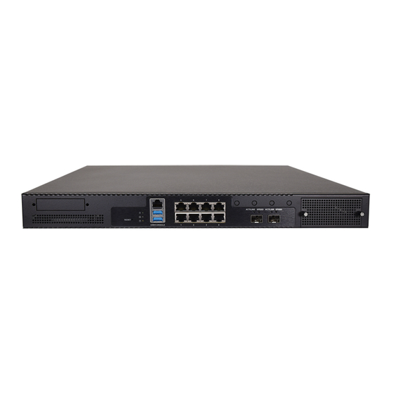
Page 12: Front Panel
NCA-2523 User Manual Front Panel Description 1x PGN Front Slot for PGN-750 (Optional) Reset Button 1x Reset Button System LED Indicators Power System Status USB Port 2x USB 3.0 Ports Console Port 1x RJ45 Console Port LAN Port 8x GbE RJ45 Ports... -
Page 13: Rear Panel
NCA-2523 User Manual Rear Panel Description ESD Screw 1x ESD Jack Cooling Fan 3x Cooling Smart Fans Ground Screw 1x Grounding Hole/Screw Power Switch 1x ATX Slim Type Power Switch SKU A/B: 300W 1+1 Redundant PSU Power Supply SKU C/D: 350W Single PSU... -
Page 14: Chapter 2: Motherboard Information
NCA-2523 User Manual CHAPTER 2: MOTHERBOARD INFORMATION Block Diagram The block diagram indicates how data flows among components on the motherboard. Please refer to the following figure for your motherboard’s layout design. -
Page 15: Motherboard Layout
NCA-2523 User Manual Motherboard Layout The motherboard layout shows the connectors and jumpers on the board. Refer to the following picture as a reference of the pin assignments and the internal connectors. -
Page 16: Internal Jumper & Connectors
NCA-2523 User Manual Internal Jumper & Connectors The pin headers on the motherboard are often associated with essential functions. With the shunt (Jumper) pushed down on the designated pins (the pin numbers are printed on the circuit board, surrounding the pin header), particular features can be enabled or disabled. While changing the jumpers, make sure your system is completely turned off. - Page 17 NCA-2523 User Manual 5. FAN3: Fan 3 Connector Description TACH 6. JPMBUS5901: Description PMBUS_TTL1 PMBUS_TTL2 PMBUS_I2C_SCL PMBUS_I2C_SDA 7. JPWR5301: Description PWRBTN_N 8. PW5903 Description...
- Page 18 NCA-2523 User Manual 9. PGNCON1 Description PGN_USB3_TXP PGN_USB3_TXN PGN_USB3_RXN PGN_USB3_RXP 10. PW5902 Description PSON 5VSB...
- Page 19 NCA-2523 User Manual 11. SATA4101 Description SATA_TXP SATA_TXN SATA_RXN SATA_RXP 12. JSPIROM2801 Description BIOS_HOLD BIOS_CS BIOS_MISO BIOS_CLK BIOS_MOSI 13. JRTC701 Description 3V3_RTC SOC_SRTCRST_N 14. JRTC702 Description 3V3_RTC SOC_RTEST_N...
- Page 20 NCA-2523 User Manual 15. J80PORT4601 Description LPC_CLK LPC_LAD1 RST_N LPC_LAD0 LPC_FRAME_N LPC_LAD3 LPC_LAD2 16. CON3901 Description MCU_UART_RXD MCU_UART_TXD 17. CON3902 Description MCU_SWD_CLK MCU_SWD_DIO 18. JGPIO4501 Description GPI1 GPO1 GPI2 GPO2 GPI3 GPO3 GPI4 GPO4...
- Page 21 NCA-2523 User Manual Install Jumper (1-3) and (2-4) for EM9191. Remove Jumper for others modules. 19. J4201 Description M2B2_P20_PCIE_DIS M2B2_P22_VBUS_SENSE 20. J4701 Description CPLD_I2C_CLK CPLD_I2C_DAT 21. JCPLD4801 Description JTAG_PLD_TCK JTAG_PLD_TDO JTAG_PLD_TMS JTAG_PLD_TDI 22. COM4601 Description HDD_LED_N COM2_DCD_N COM2_DSR_N COM2_RXD COM2_RTS_N...
- Page 22 NCA-2523 User Manual COM2_DTR_N COM2_CTS_N COM2_RI_N Remove jumper for Normal operating. 23. J1101 Description PD 20K H (1-2) = Normal mode L (2-3) = ISP mode 24. JMCU3901 Description PD 20K 25. JOPEN4501 Description CASEOPEN0_N...
-
Page 23: Chapter 3: Hardware Setup
NCA-2523 User Manual CHAPTER 3: HARDWARE SETUP To reduce the risk of personal injury, electric shock, or damage to the system, please remove all power connections to completely shut down the device, and wear ESD protection gloves when handling the installation steps. -
Page 24: Installing System Memory
NCA-2523 User Manual Installing System Memory The motherboard supports 2 memory slots for DDR4 SODIMM with speeds of up to 2933MHz for additional system memory. Please follow the procedures for installation 1. Power off the system, turn the system around, and open the chassis cover. -
Page 25: Installing M.2 Storage (Optional)
NCA-2523 User Manual Installing M.2 Storage (Optional) The motherboard supports one M.2 M-Key 2280 storage slot. Please follow the steps for installation. 1. Power off the system and open the cover. 2. Unscrew the four (4) screws of the fan hood/shroud covering the CPU. -
Page 26: Installing Disk Drive(S) (Optional)
NCA-2523 User Manual Installing Disk Drive(s) (Optional) The HDD/SSD bay supports one 2.5” SATA HDD/SSD for additional data storage. Follow the steps below for installation. After you have installed the drives on the disk bay, make sure the SATA data cables and SATA power cables are connected to the designated connectors on the motherboard. - Page 27 NCA-2523 User Manual 8. Then slide the PGN bracket back on top of the disk and secure with the original four (4) screws. 9. Then, insert the other end of the SATA data cable into the corresponding connector on the motherboard.
-
Page 28: Installing 5G/Lte Module Card (Optional)
NCA-2523 User Manual Installing 5G/LTE Module Card (Optional) The motherboard provides one M.2 slot for 5G/LTE module card. LTE module will require two (2) antennas, and 5G module will require four (4) antennas. Follow the steps for installation. The 5G/LTE Module Card kit contains the... - Page 29 NCA-2523 User Manual Installing 5G Antennas A1 A2 1. Locate the four (4) antenna hole (A1, A2, A3, A4) placement. Locate the four (4) IPEX connectors (A1, A2, A3, A4) on the 5G module card. 2. Connect the RF cables to the IPEX connectors on the 5G module card, and screw the other end of the cable in the antenna holes.
- Page 30 NCA-2523 User Manual Installing LTE Antennas 1. Locate the two (2) antenna hole (A1, A2) placement. Locate the two (2) IPEX connectors (A1, A2) on the LTE module card. 2. Connect the RF cables to the IPEX connectors on the 5G module card, and screw the other end of the cable in the antenna holes.
-
Page 31: Installing Nic Modules (Optional)
NCA-2523 User Manual Installing NIC Modules (Optional) NCA-2523 comes with one NIC module slot for expansion. Follow the steps for installation. 1. Locate the NIC module slot on the front panel of the system. 2. Rotate clockwise and loosen the two lock-screws, and remove the NIC module slot door. -
Page 32: Installing Pgn Module (Optional)
NCA-2523 User Manual Installing PGN Module (Optional) NCA-2523 comes with one PGN module slot for 5G add-on. Follow the steps for installation. The PGN module kit contains the following items: 1x PGN Module 4x Antennas PGN-750 Module Antennas Installing SIM Cards 1. - Page 33 NCA-2523 User Manual Installing PGN Cable to PGN Bracket 1. Hold the PGN bracket and insert the PGN cable to the bottom section, and secure with two (2) screws. 2. Insert the PGN bracket into the disk tray bracket, and secure with four (4) screws.
- Page 34 NCA-2523 User Manual 3. Once the module is firmly seated, secure with the two (2) original screws. 4. Secure the four (4) antennas on the front side of the PGN module.
-
Page 35: Replacing The Power Supply Unit
NCA-2523 User Manual Replacing the Power Supply Unit Power supply units may wear down eventually. Please be noted that NCA-2523 series supports 300W 1+1 redundant (SKU A/B), and 350W single (SKU C/D) power supply. Please prepare the power supply unit matching this capacity. -
Page 36: Mounting The System
NCA-2523 User Manual Mounting the System There are two methods for installing this system into a rack: With Mounting Ear Brackets only This method is quick and easy by fixing this system to the front posts of the rack, but it also makes servicing the system more difficult. - Page 37 NCA-2523 User Manual Installing the System Using Mounting Ear Brackets Only 1. Check the accessory pack for the following items: 1x Screw Pack 2x Ear Brackets Screw Pack Ear Brackets 2. Align the bracket to the side of the chassis and...
- Page 38 NCA-2523 User Manual Installing the System Using the Slide Rail Kit (with Mounting Ear Brackets) 1. Check the package contents of the Slide Rail Kit. The kit shall include the following items: 1x pack of M4X4L screws (for 7.1 Round Hole Screws...
- Page 39 NCA-2523 User Manual 5. Align the bracket to the side of the chassis and make sure the screw- holes are matched, and then secure the bracket onto the chassis with three provided M4X4L screws. Align the screws with the holes indicated on the brackets and the screw holes on the side of the chassis.
- Page 40 NCA-2523 User Manual 9. For the rear rack installation, slide the rail to aim and engage the bolts on the rail’s rear end with the two available holes on the post, and the rail assembly will click into place. Click 10.
- Page 41 NCA-2523 User Manual 12. While pushing in the system, also push and hold the Rail Lock tab on both brackets. Rail Lock Push the system all the way in until it stops. To remove the system from the rack, gently pull it outwards, towards you, while pushing the Release Tab on both sides of the brackets.
-
Page 42: Chapter 4: Software Setup
NCA-2523 User Manual CHAPTER 4: SOFTWARE SETUP BIOS Setup The system has AMI BIOS built-in, with a SETUP utility that allows users to configure required settings or to activate certain system features. Pressing the <Tab> or <DEL> key immediately allows you to enter the Setup Utility. -
Page 43: Main Page
NCA-2523 User Manual Main Page Setup Main Page contains BIOS information and project version information. Feature Description BIOS Vendor: American Megatrends Core Version: AMI Kernel version, CRB code base, X64 Compliancy: UEFI version, PI version BIOS Information Project Version: BIOS release version... -
Page 44: Advanced Page
NCA-2523 User Manual Advanced Page Select the Advanced menu tab from the BIOS setup screen to enter the “Advanced” setup screen. Users can select any of the items in the left frame of the screen. - Page 45 NCA-2523 User Manual Trusted Computing Feature Options Description Enables or disables BIOS support for security device. By Security Device Enabled disabling this function, OS will not show Security Device. Support Disabled TCG EFI protocol and INT1A interface will not be available.
- Page 46 NCA-2523 User Manual Enabled Platform Hierarchy Enables or disables Platform Hierarchy. Disabled Enabled Storage Hierarchy Enables or disables Storage Hierarchy. Disabled Endorsement Enabled Enables or disables Endorsement Hierarchy. Hierarchy Disabled Select the TCG2 Spec Version, TPM2.0 UEFI Spec TCG_1_2 TCG_1_2: Supports the Compatible mode for Win8/Win10...
- Page 47 NCA-2523 User Manual Super IO Configuration...
- Page 48 NCA-2523 User Manual Serial Port 1 Configuration Feature Options Description Enabled Serial Port Enable or Disable Serial Port (COM) Disabled Device Settings...
- Page 49 NCA-2523 User Manual Serial Port 2 Configuration Feature Options Description Enabled Serial Port Enable or Disable Serial Port (COM) Disabled Device Settings...
- Page 50 NCA-2523 User Manual H/W Monitor Feature Options Description Manual mode Smart Fan 2 Mode Smart Fan 2 Mode Select Smart Fan IV...
- Page 51 NCA-2523 User Manual Case Open Configuration Feature Options Description Enabled Case Open Enable or Disable Case Open function Disabled...
- Page 52 NCA-2523 User Manual Serial Port Console Redirection Feature Options Description COM0 Enabled Enables or disables Console Redirection Console Redirection Disabled...
- Page 53 NCA-2523 User Manual Console Redirection Settings Feature Options Description VT100: ASCII char set VT100 VT100+:Extends VT100 to support color, function keys, etc. VT100+ Terminal Type VT-UTF8:Uses UTF8 encoding to map Unicode chars onto 1 or VT-UTF8 more bytes ANSI ANSI: Extended ASCII char set...
- Page 54 NCA-2523 User Manual Disabled Resolution 100x31 Enables or disables extended terminal resolution Enabled VT100 LINUX XTERM86 Putty KeyPad Selects FunctionKey and KeyPad on Putty. ESCN VT400...
- Page 55 NCA-2523 User Manual PCI Subsystem Setting Feature Options Description If the system has SR-IOV capable PCIe Devices, this option Disabled SR-IOV Support enables or disables Single Root IO Virtualization Support. Enabled...
- Page 56 NCA-2523 User Manual USB Configuration Feature Options Description Enables Legacy USB support. Enabled Auto option disables legacy support if no USB devices are Legacy USB Support Disabled connected; Auto Disabled option will keep USB devices available only for EFI applications.
- Page 57 NCA-2523 User Manual Network Stack Configuration Feature Options Description Disabled Network Stack Enables or disables UEFI Network Stack Enabled Disabled Enables Ipv4 PXE Boot Support. If IPV4 is disabled, PXE Ipv4 PXE Support boot option will not be created. Enabled Disabled Enables Ipv4 HTTP Boot Support.
- Page 58 NCA-2523 User Manual SDIO Configuration Feature Options Description Auto Auto Option: Access SD device in DMA mode if controller ADMA SDIO Access Mode supports it, otherwise in PIO mode. DMA Option: Access SD SDMA device in DMA mode. PIO Option: Access SD device in PIO mode.
- Page 59 NCA-2523 User Manual Control PXE Boot Feature Options Description Disabled Lan1 Control PXE Boot Control PXE Boot from which Lan Lan2 from Lan3 Lan4...
- Page 60 NCA-2523 User Manual TruOpt FORM Feature Options Description Optimize TruOpt Lanner optimization Manual...
-
Page 61: Platform
NCA-2523 User Manual Platform Select the Platform menu tab from the BIOS setup screen to enter the “Platform” setup screen. Users can select any of the items in the left frame of the screen. Feature Options Description PCH-IO None PCH Parameters... - Page 62 NCA-2523 User Manual PCH-IO Configuration Feature Options Description PCH SATA None Device Options settings Configuration Power On Restore AC Select S0/S5 for ACPI state after a G3 Power Off Power Loss Last State Quiet Serial IRQ Mode Configure Serial IRQ Mode.
- Page 63 NCA-2523 User Manual SATA Configuration Feature Options Description Disabled SATA Configuration SATA test settings Enabled Disabled Aggressive LPM Support Enable PCH to aggressively enter link power state. Enabled...
- Page 64 NCA-2523 User Manual Server ME Configuration...
- Page 65 NCA-2523 User Manual System Event Log Feature Options Description Disabled System Errors System Error Enable/Disable setup options. Enabled...
-
Page 66: Socket
NCA-2523 User Manual Socket Select the Socket menu tab from the BIOS setup screen to enter the “Socket” setup screen. Users can select any of the items in the left frame of the screen. Feature Options Description Displays and provides option to change the Processor... - Page 67 NCA-2523 User Manual Processor Configuration Feature Options Description Disabled Machine Check Enable or Disable the Machine Check Enabled Disabled Hardware Prefetcher = MLC Streamer Prefetcher (MSR 1A4h Bit [0]) Enabled Disabled Adjacent Cache Prefetcher = MLC Spatial Prefetcher (MSR 1A4h Bit [1])
- Page 68 NCA-2523 User Manual Disabled Enables the Vanderpool Technology, which takes effect Enabled after reboot. Disabled Enable SMX Enables Safer Mode Extensions Enabled Disabled AES-NI Enable/disable AES-NI support Enabled...
- Page 69 NCA-2523 User Manual Per-Socket Configuration Feature Options Description Core Disable Bitmap (Hex) 0: Enable All cores. FFFFFFFFFFF: Disable all cores...
- Page 70 NCA-2523 User Manual Memory Configuration Feature Options Description Displays memory topology with DIMM population Memory Topology None information...
- Page 71 NCA-2523 User Manual IIO Configuration Feature Options Description IOAT Configuration None All IOAT configuration options Intel® VT for Directed I/O Press <Enter> to bring up the Intel® VT for Directed I/O None (VT-d) (VT-d) Configuration menu. PCI-E ASPM This option enables / disables the ASPM support for all...
- Page 72 NCA-2523 User Manual IOAT Configuration Feature Options Description Sck0 IOAT Config None None Disable TPH TLP Processing Hint disable Disabled Prioritize TPH Prioritize TPH Enabled Relaxed Ordering Relaxed Ordering Enable/Disable...
- Page 73 NCA-2523 User Manual Intel® VT for Directed I/O (VT-d) Feature Options Description Enable/Disable Intel® Virtualization Technology for Directed Disabled Intel® VT for Directed I/O I/O (VT-d) by reporting the I/O device assignment to VMM Enabled through DMAR ACPI Tables.
- Page 74 NCA-2523 User Manual Advanced Power Management Configuration Feature Options Description P State Control Configuration Sub Menu, include Turbo, XE CPU P State Control None and etc.
- Page 75 NCA-2523 User Manual CPU P State Control Feature Options Description Disabled SpeedStep (Pstates) Enables or disables EIST (P-States) Enabled Max Performance Boot performance Select the performance state that the BIOS will set Max Efficient mode before OS hand off. Set by Intel Node Manager...
-
Page 76: Security
NCA-2523 User Manual Security Select the Security menu item from the BIOS setup screen to enter the Security Setup screen. Users can select any of the items in the left frame of the screen. Feature Description Administrator If ONLY the Administrator's password is set, it only limits access to Password Setup and is only asked for when entering Setup. - Page 77 NCA-2523 User Manual Secure Boot Feature Options Description Secure Boot is activated when Platform Key (PK) is enrolled, Disabled Secure Boot Enable System mode is User/Deployed, and CSM function is disabled. Enabled Customizable Secure Boot mode: In Custom mode, Secure Boot...
- Page 78 NCA-2523 User Manual Key Management Feature Options Description Provision factory default keys on next re-boot only when Disabled Factory Key Provision System in Setup Mode. Enabled Force System to User Mode. Configure NVRAM to contain Restore Factory keys None OEM-defined factory default Secure Boot keys.
-
Page 79: Boot Menu
NCA-2523 User Manual Boot Menu Select the Boot menu tab from the BIOS setup screen to enter the “Boot” setup screen. Users can select any of the items in the left frame of the screen. Feature Options Description The number of seconds to wait for setup activation key. -
Page 80: Save And Exit Menu
NCA-2523 User Manual Save and Exit Menu Select the Save and Exit menu tab from the BIOS setup screen to enter the “Save and Exit” setup screen. Users can select any of the items in the left frame of the screen. - Page 81 NCA-2523 User Manual ■ Restore Defaults Restore default values for all setup options. Select “Yes” to load Optimized defaults. Note: The items under Boot Override may not be the same as the above images, as it should depend on the...
-
Page 82: Appendix A: Led Indicator Explanations
NCA-2523 User Manual APPENDIX A: LED INDICATOR EXPLANATIONS The status explanations of LED indicators on Front Panel are as follows: Green: System Power Red/Green: System Status Amber: HDD Activity COLOR LED ACTION DESCRIPTION Green Steady System is powered ON Power... - Page 83 NCA-2523 User Manual 10Gb SFP+ Light pipe LED (top location) Define: Speed Amber (Active) Amber Green (Link) Blinking / Data access ON (Amber) Blinking / Steady ON (Green) Non-Link 1. When cable is plug-in and network is linked. Both LED will be bright. The behavior is as defined.
-
Page 84: Appendix B: Dual Bios Introduction
To provide increased flexibility and usage protection, Lanner has released the 2nd Gen Dual BIOS function on Lanner appliances. With 2nd Gen Dual BIOS, both the primary BIOS and secondary BIOS can be updated and flashed using the BIOS Tool to run different versions of BIOS ROMS independently for maximum compatibility. - Page 85 Lanner Technical Support. Warning DO NOT power off or reset the system during BIOS updating process. Disclaimer Under no circumstances will Lanner accept responsibility or liability for damages of any kind whatsoever resulting or arising directly or indirectly from a BIOS update.
-
Page 86: Appendix C: Smart Power And Reset Button
NCA-2523 User Manual APPENDIX C: SMART POWER AND RESET BUTTON Smart Power and Reset Button – Controlled by CPLD Reset Button Power Button... -
Page 87: Appendix D: Esd/Surge Enhancement
NCA-2523 User Manual APPENDIX D: ESD/SURGE ENHANCEMENT Electrostatic Discharge (ESD): Contact Discharge Air Discharge IEC-61000-4-2 Level 1 ±2 kV ±2 kV Level 2 ±4 kV ±4 kV 4K Contact Level 3 ±6 kV ±8 kV 8K Air Level 4 (Requirement) ±8 kV... -
Page 88: Appendix E: Terms And Conditions
NCA-2523 User Manual APPENDIX E: TERMS AND CONDITIONS Warranty Policy 1. All products are under warranty against defects in materials and workmanship for a period of one year from the date of purchase. 2. The buyer will bear the return freight charges for goods returned for repair within the warranty period;... - Page 89 NCA-2523 User Manual RMA Service Request Form When requesting RMA service, please fill out the following form. Without this form enclosed, your RMA cannot be processed.
Need help?
Do you have a question about the NCA-2523 and is the answer not in the manual?
Questions and answers