Advertisement
Quick Links
Advertisement

Related Manuals for Lanner NCA-2522


Summary of Contents for Lanner NCA-2522
- Page 1 Network Computing NCA-2522 User Manual Version: 1.0 Date of Release: 2022-08-31...
- Page 2 - assumed to be qualified in the servicing of computer equipment, such as professional system integrators, or service personnel and technicians. The latest version of this document can be found on Lanner’s official website, available either through the product page or through the Lanner Download Center page with a login account and password.
- Page 3 NCA-2522 User Manual Taiwan Corporate Headquarters China Lanner Electronics Inc. Beijing L&S Lancom Platform Tech. Co., Ltd. 7F, No.173, Sec.2, Datong Rd. Guodong LOFT 9 Layer No. 9 Huinan Road, Xizhi District, New Taipei City 22184, Huilongguan Town, Changping District, Beijing...
- Page 4 NCA-2522 User Manual This document is copyrighted © 2022. All rights are reserved. The original manufacturer reserves the right to make improvements to the products described in this manual at any time without notice. No part of this manual may be reproduced, copied, translated or transmitted in any form or by any means without the prior written permission of the original manufacturer.
- Page 5 NCA-2522 User Manual Follow these guidelines to ensure general safety: Keep the chassis area clear and dust-free during and after installation. Do not wear loose clothing or jewelry that could get caught in the chassis. Fasten your tie or scarf and roll up your sleeves.
- Page 6 The installation of this product must be performed by trained specialists; otherwise, a non-specialist might create the risk of the system’s falling to the ground or other damages. Lanner Electronics Inc. shall not be held liable for any losses resulting from insufficient strength for supporting the system or use of inappropriate installation components.
- Page 7 NCA-2522 User Manual Before turning on the device, ground the grounding cable of the equipment. Proper grounding (grounding) is very important to protect the equipment against the harmful effects of external noise and to reduce the risk of electrocution in the event of a lightning strike. To uninstall the equipment, disconnect the ground wire after turning off the power.
- Page 8 NCA-2522 User Manual Package Content ......................... 10 Ordering Information ......................... 10 Optional Accessories ........................11 System Specifications ......................... 12 Front Panel ..........................14 Rear Panel ........................... 15 Block Diagram ..........................16 Motherboard Layout ........................17 Internal Jumper & Connectors ....................18 Opening the Chassis ........................
- Page 9 NCA-2522 User Manual BIOS Setup ..........................45 Main Page ........................... 46 Advanced Page ........................... 47 Platform ............................66 Socket ............................71 Server Mgmt ..........................82 Security ............................93 Boot Menu ..........................96 Save and Exit Menu ........................97 Warranty Policy ........................103...
- Page 10 Intel Secure Boot, Intel Virtualization Technology, Intel QuickAssist Technology and Intel AES-NI, making it an ideal hardware solution for vCPE, uCPE, SD-WAN, and SD-Security on Intel architecture servers. Your package contains the following items: 1x NCA-2522 Network Security Platform 2x PSU Power Cord (US Standard Type Default) 1x RJ45 Console Cable...
- Page 11 NCA-2522 User Manual Model No. Description Riser Card Kit NCA-2520 Riser Card Kit for rear side PCIe expansion (By Project) IO & Riser Card Kit Upper layer IO-2520IXM401A+RC-25102A (By Project) IAC-AST2401A IPMI (Intelligent Platform Management Interface) Card Module IAC-TPM04A TPM 2.0 Module...
- Page 12 NCA-2522 User Manual Form Factor 1U 19" Rackmount SKU A: Intel® Atom™ P5362, 24 cores, 83W SKU B: Intel® Atom™ P5352, 20 cores, 78W Processor Options SKU C: Intel® Atom™ P5342, 16 cores, 71W SKU D: Intel® Atom™ P5332, 12 cores, 61W Platform SKU E: Intel®...
- Page 13 NCA-2522 User Manual Type/Watts 300W 1+1 AC/DC Redundant CRPS Power Supply Power Input AC 90~264V @47~63Hz LINUX, UEFI BIOS Intel® Firmware Support Package (Intel® FSP) No Support for OPROMS, including PXE OPROM OS Support Manageability: SPS 5.0 FW...
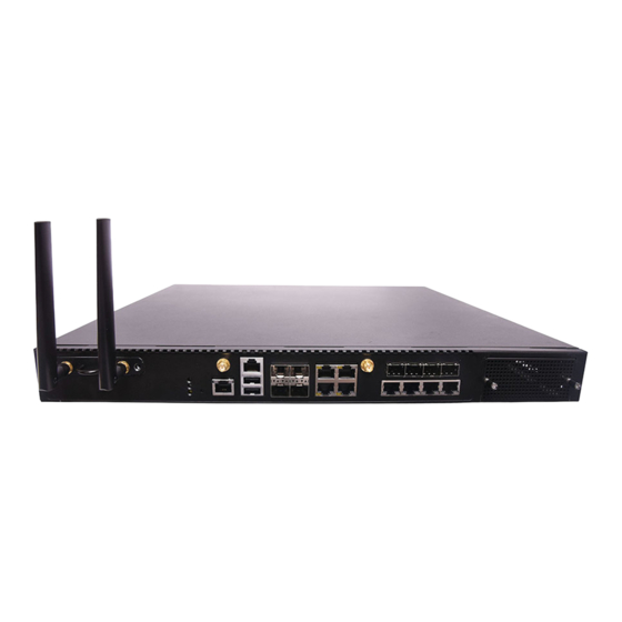
- Page 14 NCA-2522 User Manual Description 1x PGN Front Slot for PGN-300/PGN-600 (Optional) System Power LED Indicators System Status HDD Activity 1x Reset Button Reset Button LOM Port 1x LOM Port for IPMI Card Console Port 1x RJ45 Console Port USB Port 2x USB 2.0 Ports...
- Page 15 NCA-2522 User Manual Description PCIe Expansion 1x PCIE*8 or 2x PCIE*4, FH/HL Size Card at Rear (By Project) Semi-Shearing Hole DB9 or 2x DB15 and 1x USB (By Project) ESD Screw 1x ESD Jack Cooling Fan 3x Cooling Smart Fans...
- Page 16 NCA-2522 User Manual The block diagram indicates how data flows among components on the motherboard. Please refer to the following figure for your motherboard’s layout design.
- Page 17 NCA-2522 User Manual The motherboard layout shows the connectors and jumpers on the board. Refer to the following picture as a reference of the pin assignments and the internal connectors.
- Page 18 NCA-2522 User Manual The pin headers on the motherboard are often associated with essential functions. With the shunt (Jumper) pushed down on the designated pins (the pin numbers are printed on the circuit board, surrounding the pin header), particular features can be enabled or disabled. While changing the jumpers, make sure your system is completely turned off.
- Page 19 NCA-2522 User Manual 6. JRTC2: Clear CMOS Pin No. Description P3V3_RTC SOC_RESET_N 7. FAN1~3: Fan Connector Pin No. Description HM_FANOUT SYSFANIN P12V 8. J80PORT1: Port80 Connector Pin No. Description Pin No. Description CLK_LPC_OUT SOC_LPC_LAD1 80PORT_RST# SOC_LPC_LAD0 SOC_LPC_FRAME_N P3V3_S SOC_LPC_LAD3 SOC_LPC_LAD2 9.
- Page 20 NCA-2522 User Manual 10. JI01: GPI0 Header (Pitch 2.0mm) Pin No. Description Pin No. Description GP0_B_1 GPI_B_1 GP0_B_2 GPI_B_2 GP0_B_3 GPI_B_3 GP0_B_4 GPI_B_4 11. LTE_USB1: LTE Module Header Pin No. Description Pin No. Description USB2_1+ USB2_1- SIM_SW USB3_T0+ P3V3_STBY USB3_T0-...
- Page 21 NCA-2522 User Manual 14. J13: BIOS Boot Up Select Pin No. Description Force Boot Up from BIOS1(Default) Force Boot Up from BIOS2 15. JDUAL1: Select CS for Flash Fixture Pin No. Description Flash 1 BIOS(Default) Flash 2 BIOS 16. JPLD1: CPLD Programming Header Pin No.
- Page 22 NCA-2522 User Manual 19. J3: Gen3 Bypass Flash Jumper Pin No. Description Disable (Default) Enable 20. J9: SMBUS Test Header Pin No. Description P3V3_STBY SMB_HOST_CLK SMB_HOST_DATA...
- Page 23 NCA-2522 User Manual To reduce the risk of personal injury, electric shock, or damage to the system, please remove all power connections to completely shut down the device, and wear ESD protection gloves when handling the installation steps. 1. Power off the system.
- Page 24 NCA-2522 User Manual The motherboard supports 4 memory slots for DDR4 UDIMM with speeds of up to 2933MHz. The CPU requires at least 1 memory modules to boot and run from. Total Slots Number of Channels 2 (2 DIMMs per channel)
- Page 25 NCA-2522 User Manual Recommended DIMM Population Scheme The table below shows the recommended schemes for DIMM population. To guarantee balanced system performance, please install identical DIMMs of the same capacity, speed, number of ranks, and from the same manufacturer. SLOT #...
- Page 26 NCA-2522 User Manual The motherboard supports one M.2 M-Key 2280 storage slot. Please follow the steps for installation. 1. Power off the system and open the cover. 2. Locate the M.2 slot on the motherboard. Notch 3. Align the notch of the M.2 storage card with the socket in the pin slot.
- Page 27 NCA-2522 User Manual The system provides one slot for a TPM module card to provide hardware-based security-related functions. Follow the steps below for installation. 1. Power off the system and open the cover. 2. Locate the TPM connector pins on the motherboard.
- Page 28 NCA-2522 User Manual The system supports the placement of one IPMI module card, allowing system administrators to remotely manage and monitor system health. Follow the steps below for installation. The IPMI Module Kit includes: 1x IPMI Module Card 3x Stainless Steel Standoff Pillar Studs...
- Page 29 NCA-2522 User Manual 4. Insert the IPMI module card into the socket until it is fully seated in the connector. IPMI Socket 5. Secure the IPMI module card with three (3) screws, one for each standoff pillar.
- Page 30 NCA-2522 User Manual The HDD/SSD bay supports two 2.5” SATA HDDs or SSD for additional data storage. Follow the steps below for installation. After you have installed the drives on the disk bay, make sure the SATA data cables and SATA power cables are connected to the designated connectors on the motherboard.
- Page 31 NCA-2522 User Manual 5. Attach the SATA data cable and power cable to the HDD/SSD disk. 6. Place the tray (with the disk drives now installed) back to its original place inside the system. Secure with the original one (1) screw.
- Page 32 NCA-2522 User Manual The motherboard provides one mini-PCIe slot, to support one Wi-Fi module card. Wi-Fi module will also require two (2) antennas. Follow the steps for installation. The Wi-Fi Module Card kit contains the following items: 1x Wi-Fi Module Card...
- Page 33 NCA-2522 User Manual Installing Wi-Fi Antennas 1. Locate the IPEX connectors (A1, A2) on the Wi-Fi module card. 2. Connect the cables to the Wi-Fi module card IPEX connectors. 3. Screw on the two (2) antennas on the outside of the system.
- Page 34 NCA-2522 User Manual NCA-2522 comes with one NIC module slot for expansion. Follow the steps for installation. 1. Locate the NIC module slot on the front panel of the system. 2. Rotate clockwise and loosen the two lock-screws, and remove the NIC module slot door.
- Page 35 NCA-2522 User Manual NCA-2522 comes with one PGN module slot for 4G/LTE add-on. Follow the steps for installation. Setting up the PGN Module 1. Loosen the two (2) screws on each side of the PGN module and lift up the cover.
- Page 36 NCA-2522 User Manual Installing LTE Antennas 1. Locate the IPEX connectors (A1, A2) on the LTE module card. 2. Connect the cables to the LTE module card IPEX connectors. 3. Place the top cover back on and secure with two (2) screws on each side.
- Page 37 NCA-2522 User Manual Installing PGN Module 1. Locate the PGN module slot on the front panel of the system. 2. Insert a PGN module. 3. Once the module is firmly seated, secure with the two (2) original screws. And 4. Secure the two (2) antennas on the front side of...
- Page 38 NCA-2522 User Manual Power supply units may wear down eventually. Please be noted that NCA-2522 series supports 300W 1+1 AC/DC redundant CRPS power supply. Please prepare the power supply unit matching this capacity. 1. Locate the power supply unit on the rear panel of the system.
- Page 39 NCA-2522 User Manual There are two methods for installing this system into a rack: With Mounting Ear Brackets only This method is quick and easy by fixing this system to the front posts of the rack, but it also makes servicing the system more difficult.
- Page 40 NCA-2522 User Manual 1. Check the accessory pack for the following items: 1x Screw Pack 2x Ear Brackets Screw Pack Ear Brackets 2. Align the bracket to the side of the chassis and make sure the screw-holes are matched, and then secure the bracket onto the chassis with three provided screws.
- Page 41 NCA-2522 User Manual 1. Check the package contents of the Slide Rail Kit. The kit shall include the following items: 1x pack of M4X4L screws (for 7.1 Round Hole Screws M4X4L Screws securing the Rail Brackets on the system) 1x pack of 7.1 Round Hole...
- Page 42 NCA-2522 User Manual 5. Align the bracket to the side of the chassis and make sure the screw- holes are matched, and then secure the bracket onto the chassis with three provided M4X4L screws. Align the screws with the holes indicated on the brackets and the screw holes on the side of the chassis.
- Page 43 NCA-2522 User Manual 9. For the rear rack installation, slide the rail to aim and engage the bolts on the rail’s rear end with the two available holes on the post, and the rail assembly will click into place. Click 10.
- Page 44 NCA-2522 User Manual 12. While pushing in the system, also push and hold the Rail Lock tab on both brackets. Rail Lock Push the system all the way in until it stops. To remove the system from the rack, gently pull it outwards, towards you, while pushing the Release Tab on both sides of the brackets.
- Page 45 NCA-2522 User Manual The system has AMI BIOS built-in, with a SETUP utility that allows users to configure required settings or to activate certain system features. Pressing the <Tab> or <DEL> key immediately allows you to enter the Setup Utility.
- Page 46 NCA-2522 User Manual Setup Main Page contains BIOS information and project version information. Feature Description BIOS Vendor: American Megatrends Core Version: AMI Kernel version, CRB code base, X64 Compliancy: UEFI version, PI version BIOS Information Project Version: BIOS release version...
- Page 47 NCA-2522 User Manual Select the Advanced menu tab from the BIOS setup screen to enter the “Advanced” setup screen. Users can select any of the items in the left frame of the screen.
- Page 48 NCA-2522 User Manual Feature Options Description Enables or disables BIOS support for security device. By Security Device Enabled disabling this function, OS will not show Security Device. Support Disabled TCG EFI protocol and INT1A interface will not be available.
- Page 49 NCA-2522 User Manual...
- Page 50 NCA-2522 User Manual Feature Options Description Enabled Serial Port Enable or Disable Serial Port (COM) Disabled Device Settings...
- Page 51 NCA-2522 User Manual Feature Options Description Enabled Serial Port Enable or Disable Serial Port (COM) Disabled Device Settings...
- Page 52 NCA-2522 User Manual Feature Options Description Manual mode Smart Fan 2 Mode Smart Fan 2 Mode Select Smart Fan IV...
- Page 53 NCA-2522 User Manual Feature Options Description Enabled Case Open Enable or Disable Case Open function Disabled...
- Page 54 NCA-2522 User Manual Feature Options Description Status LED GREEN Configures Status LED color...
- Page 55 NCA-2522 User Manual Feature Options Description Output High Digital I/O Output 1 Configure Digital I/O Pin1 Output Low Output High Digital I/O Output 2 Configure Digital I/O Pin3 Output Low Output High Digital I/O Output 3 Configure Digital I/O Pin5...
- Page 56 NCA-2522 User Manual Feature Options Description Enabled Watch Dog Timer Enables or disables Watch Dog Timer function Disabled Watch Dog Timer Second Mode Select Second Mode or Minute Mode Count Mode Minute Mode Watch Dog Timer Watch Dog Timer Time out Value.
- Page 57 NCA-2522 User Manual Feature Options Description COM0 Enabled Enables or disables Console Redirection Console Redirection Disabled...
- Page 58 NCA-2522 User Manual Feature Options Description VT100: ASCII char set VT100 VT100+:Extends VT100 to support color, function keys, etc. VT100+ Terminal Type VT-UTF8:Uses UTF8 encoding to map Unicode chars onto 1 VT-UTF8 or more bytes. ANSI ANSI: Extended ASCII char set...
- Page 59 NCA-2522 User Manual VT-UTF8 Combo Disabled Enables VT-UTF8 Combination Key Support for ANSI/VT100 Key Support Enabled terminals Disabled With this mode enabled, only text will be sent. This is to Recorder Mode Enabled capture Terminal data. Disabled Resolution 100x31 Enables or disables extended terminal resolution...
- Page 60 NCA-2522 User Manual Feature Options Description If the system has SR-IOV capable PCIe Devices, this option Disabled SR-IOV Support enables or disables Single Root IO Virtualization Support. Enabled...
- Page 61 NCA-2522 User Manual Feature Options Description Enables Legacy USB support. Enabled Auto option disables legacy support if no USB devices are Legacy USB Support Disabled connected; Auto Disabled option will keep USB devices available only for EFI applications. USB Mass Storage Enabled Enables or disables USB Mass Storage Driver Support.
- Page 62 NCA-2522 User Manual Feature Options Description Disabled Network Stack Enables or disables UEFI Network Stack Enabled Disabled Enables Ipv4 PXE Boot Support. If IPV4 is disabled, PXE Ipv4 PXE Support boot option will not be created. Enabled Disabled Enables Ipv4 HTTP Boot Support. If IPV4 is disabled, HTTP Ipv4 HTTP Support boot option will not be created.
- Page 63 NCA-2522 User Manual...
- Page 64 NCA-2522 User Manual Feature Options Description Disabled Control PXE Boot Control PXE Boot from which Lan Lan0 from Lan1...
- Page 65 NCA-2522 User Manual Feature Options Description Optimize TruOpt Lanner optimization Manual...
- Page 66 NCA-2522 User Manual Select the Platform menu tab from the BIOS setup screen to enter the “Platform” setup screen. Users can select any of the items in the left frame of the screen. Feature Options Description PCH-IO None PCH Parameters...
- Page 67 NCA-2522 User Manual Feature Options Description PCH SATA None Device Options settings Configuration Power On Restore AC Power Select S0/S5 for ACPI state after a G3 Power Off Loss Last State Quiet Serial IRQ Mode Configure Serial IRQ Mode. Continuous...
- Page 68 NCA-2522 User Manual Feature Options Description Disabled SATA Configuration SATA test settings Enabled Disabled Aggressive LPM Support Enable PCH to aggressively enter link power state. Enabled...
- Page 69 NCA-2522 User Manual...
- Page 70 NCA-2522 User Manual Feature Options Description Disabled System Errors System Error Enable/Disable setup options. Enabled...
- Page 71 NCA-2522 User Manual Select the Socket menu tab from the BIOS setup screen to enter the “Socket” setup screen. Users can select any of the items in the left frame of the screen. Feature Options Description Displays and provides option to change the Processor...
- Page 72 NCA-2522 User Manual Feature Options Description Disabled Machine Check Enable or Disable the Machine Check Enabled Disabled Hardware Prefetcher = MLC Streamer Prefetcher (MSR 1A4h Bit [0]) Enabled Disabled Adjacent Cache Prefetcher = MLC Spatial Prefetcher (MSR 1A4h Bit [1])
- Page 73 NCA-2522 User Manual Feature Options Description CPU Socket 0 Configuration...
- Page 74 NCA-2522 User Manual Feature Options Description Core Disable 0: Enable All cores. Bitmap (Hex) FFFFFFFFFFF: Disable all cores.
- Page 75 NCA-2522 User Manual Feature Options Description Displays memory topology with DIMM population Memory Topology None information...
- Page 76 NCA-2522 User Manual Feature Options Description Socket0 Configuration None None IOAT Configuration None All IOAT configuration options Intel® VT for Press <Enter> to bring up the Intel® VT for Directed I/O None Directed I/O (VT-d) (VT-d) Configuration menu. PCI-E ASPM...
- Page 77 NCA-2522 User Manual Feature Options Description Settings related to PCI Express PortS Port 1A None (0/1A/1B/1C/1D/2A/2B/2C/2D/3A/3B/3C/3D/4A/4B/4C/ Port 1C 4D/5A/5B/5C/5D)
- Page 78 NCA-2522 User Manual Feature Options Description Sck0 IOAT Config None None Disable TPH TLP Processing Hint disable Disabled Prioritize TPH Prioritize TPH Enabled Relaxed Ordering Relaxed Ordering Enable/Disable...
- Page 79 NCA-2522 User Manual Feature Options Description Enable/Disable Intel® Virtualization Technology for Directed Intel® VT for Disabled I/O (VT-d) by reporting the I/O device assignment to VMM Directed I/O (VT-d) Enabled through DMAR ACPI Tables.
- Page 80 NCA-2522 User Manual Feature Options Description P State Control Configuration Sub Menu, include Turbo, XE CPU P State Control None and etc.
- Page 81 NCA-2522 User Manual Feature Options Description Disabled SpeedStep (Pstates) Enables or disables EIST (P-States) Enabled Max Performance Boot performance Select the performance state that the BIOS will set Max Efficient mode before OS hand off. Set by Intel Node Manager...
- Page 82 NCA-2522 User Manual Select the Server Mgmt menu tab from the BIOS setup screen to enter the “Server Mgmt” setup screen. Users can select any of the items in the left frame of the screen. Feature Options Description Enabled Enable: HW detect to support BMC or not. Disable: Manual BMC HW Detect select BMC Support to Enable or Disable.
- Page 83 NCA-2522 User Manual If enabled, it starts a BIOS timer which can only be shut off by Enabled Management Software after the OS loads. It also helps verify OS Watchdog Timer that the OS is successfully loaded or follows the OS Boot Disabled Watchdog Timer policy.
- Page 84 NCA-2522 User Manual Feature Options Description Disabled Enables or disables all features of System Event Logging SEL Components during boot. Enabled Erase SEL Choose options for erasing SEL. Yes, On next reset Yes, On every reset Do Nothing When SEL is Full Choose options for reactions to a full SEL.
- Page 85 NCA-2522 User Manual...
- Page 86 NCA-2522 User Manual Feature Options Description Yes, On every reset Erase Log Erase Log Options Clear Log When log is full Select the action to be taken when log is full Do not log any more...
- Page 87 NCA-2522 User Manual Feature Options Description Select to configure LAN channel parameters statically Unspecified or dynamically (by BIOS or BMC). Unspecified option Configuration Static will not modify any BMC network parameters during Address source DynamicBmcDhcp BIOS phase DynamicBmcNonDhcp Feature Options Description Enable or Disable LAN1 IPV6 Support.
- Page 88 NCA-2522 User Manual...
- Page 89 NCA-2522 User Manual Feature Options Description Add User Press <Enter> to Add a User. Delete User Press <Enter> to Delete a User. Change User Settings Press <Enter> to Change User Settings.
- Page 90 NCA-2522 User Manual Feature Options Description User Name Enter BMC User Name User Password Enter BMC User Password Channel No Enter BMC Channel Number Reserved Callback User Privilege User Enter BMC User Privilege Limit for Selected Channel Limit Operator Administrator...
- Page 91 NCA-2522 User Manual Feature Options Description User Name Enter BMC User Name User Password Enter BMC User Password...
- Page 92 NCA-2522 User Manual Feature Options Description User Name Enter BMC User Name User Password Enter BMC User Password Enabled User Enable/Disable the User. Disabled Change User Enter New Password to change. Password" Channel No Enter BMC Channel Number Reserved Callback...
- Page 93 NCA-2522 User Manual Select the Security menu tab from the BIOS setup screen to enter the “Security” setup screen. Users can select any of the items in the left frame of the screen. Feature Description Administrator ONLY when the Administrator's password is set, it only limits access to Setup Password and is only asked for when entering Setup.
- Page 94 NCA-2522 User Manual Feature Options Description Secure Boot is activated when Platform Key (PK) is enrolled, Disabled Secure Boot Enable System mode is User/Deployed, and CSM function is disabled. Enabled Customizable Secure Boot mode: In Custom mode, Secure Boot Standard...
- Page 95 NCA-2522 User Manual Feature Options Description Provision factory default keys on next re-boot only when Disabled Factory Key Provision System in Setup Mode. Enabled Force System to User Mode. Configure NVRAM to contain Restore Factory keys None OEM-defined factory default Secure Boot keys.
- Page 96 NCA-2522 User Manual Select the Boot menu tab from the BIOS setup screen to enter the “Boot” setup screen. Users can select any of the items in the left frame of the screen. Feature Options Description The number of seconds to wait for setup activation key.
- Page 97 NCA-2522 User Manual Select the Save and Exit menu tab from the BIOS setup screen to enter the “Save and Exit” setup screen. Users can select any of the items in the left frame of the screen. ■ Discard Changes and Exit Select this option to quit Setup without saving any modifications to the system configuration.
- Page 98 NCA-2522 User Manual ■ Restore Defaults Restore default values for all setup options. Select “Yes” to load Optimized defaults. Note: The items under Boot Override may not be the same as the above images, as it should depend on the...
- Page 99 NCA-2522 User Manual The status explanations of LED indicators on Front Panel are as follows: Green: System Power Red/Green: System Status Amber: HDD Activity COLOR LED ACTION DESCRIPTION Green Steady System is powered ON Power System is powered OFF Green...
- Page 100 To provide increased flexibility and usage protection, Lanner has released the 2nd Gen Dual BIOS function on Lanner appliances. With 2nd Gen Dual BIOS, both the primary BIOS and secondary BIOS can be updated and flashed using the BIOS Tool to run different versions of BIOS ROMS independently for maximum compatibility.
- Page 101 Lanner Technical Support. Warning DO NOT power off or reset the system during BIOS updating process. Disclaimer Under no circumstances will Lanner accept responsibility or liability for damages of any kind whatsoever resulting or arising directly or indirectly from a BIOS update.
- Page 102 NCA-2522 User Manual Smart Power and Reset Button – Controlled by CPLD Reset Button Power Button...
- Page 103 NCA-2522 User Manual 1. All products are under warranty against defects in materials and workmanship for a period of one year from the date of purchase. 2. The buyer will bear the return freight charges for goods returned for repair within the warranty period;...
- Page 104 NCA-2522 User Manual When requesting RMA service, please fill out the following form. Without this form enclosed, your RMA cannot be processed.
Need help?
Do you have a question about the NCA-2522 and is the answer not in the manual?
Questions and answers