
Related Manuals for Lanner NCA-1516


Summary of Contents for Lanner NCA-1516
- Page 1 NCA-1516 User Manual Network Appliance Platform NCA-1516 User Manual Version: 1.1 Date of Release:2021-10-29...
- Page 2 - assumed to be qualified in the servicing of computer equipment, such as professional system integrators, or service personnel and technicians. The latest version of this document can be found on Lanner’s official website, available either through the product page or through the Lanner Download Center page with a login account and password.
- Page 3 NCA-1516 User Manual In addition to contacting your distributor or sales representative, you could submit a request to our Lanner Technical Support at http://www.lannerinc.com/technical-support where you can fill in a support ticket to our technical support department. This document is copyrighted © 2021 by Lanner Electronics Inc. All rights are reserved. The original manufacturer reserves the right to make improvements to the products described in this manual at any time without notice.
- Page 4 NCA-1516 User Manual Taiwan Corporate Headquarters China Lanner Electronics Inc. Beijing L&S Lancom Platform Tech. Co., Ltd. 7F, No.173, Sec.2, Datong Rd. Guodong LOFT 9 Layer No. 9 Huinan Road, Xizhi District, New Taipei City 22184, Huilongguan Town, Changping District, Beijing...
- Page 5 NCA-1516 User Manual Intel® and Intel® Atom® are trademarks of Intel Corporation or its subsidiaries in the U.S. and/or other countries. Microsoft Windows and MS-DOS are registered trademarks of Microsoft Corp. All other product names or trademarks are properties of their respective owners.
- Page 6 NCA-1516 User Manual Follow these guidelines to ensure general safety: Keep the chassis area clear and dust-free during and after installation. Do not wear loose clothing or jewelry that could get caught in the chassis. Fasten your tie or scarf and roll up your sleeves.
- Page 7 The installation of this product must be performed by trained specialists; otherwise, a non-specialist might create the risk of the system’s falling to the ground or other damages. Lanner Electronics Inc. shall not be held liable for any losses resulting from insufficient strength for supporting the system or use of inappropriate installation components.
- Page 8 NCA-1516 User Manual Un câble de mise à la terre est requis et la zone reliant les sections du conducteur doit faire plus de 4 mm2 ou 10 AWG. Loosen the screw of the earthing point. Connect the grounding cable to the ground.
- Page 9 NCA-1516 User Manual Package Content ......................... 10 Optional Kits ..........................10 Ordering Information ......................... 10 System Specifications ......................... 11 Front Panel ..........................12 Rear Panel ........................... 13 Motherboard Information ......................14 Opening the Chassis ........................21 Installing M.2 module for Storage ....................22 Installing System Memory ......................
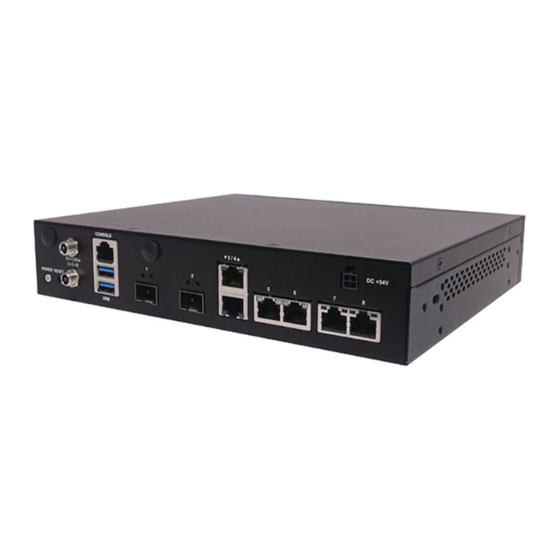
- Page 10 NCA-1516 User Manual The NCA-1516, a desktop network appliance powered by Intel® Atom® C3000, is capable of both mmWave 5G, Sub-6GHz 5G and its WIfi6 is both 2.4G and 5G compatible. Hardware performance is supercharged with Intel’s QuickAssist Technology and Intel® AES-NI. The NCA-1516 is equipped with ample network communication features and configurations for vCPE/uCPE and Edge security.
- Page 11 NCA-1516 User Manual Form Factor Desktop Processor Options Intel® Atom® C3000 CPU Socket 1 x Onboard Platform Chipset Security Acceleration Intel® QuickAssist Technology BIOS AMI SPI Flash BIOS DDR4 1866/2133/2400MHz ECC/Non- Technology ECC (By SKU) System Memory Max. Capacity 64GB...
- Page 12 NCA-1516 User Manual Description 2 x Nano SIM Slots SIM Card Slot SFP2 System Power LED Indicators System Status HDD Activity SFP1 LAN 3~8 2 x SMA connector for LTE module Antenna Port...
- Page 13 NCA-1516 User Manual Description Press to power on/off the system Power Switch Press to perform a Hardware reset Reset Button DC Jack Power supply 1x RJ45 console port Console Port 2 x USB 3.0 port USB Port 2 x SFP port...
- Page 14 NCA-1516 User Manual The block diagram indicates how data flows among components on the motherboard. Please refer to the following figure for your motherboard’s layout design.
- Page 15 NCA-1516 User Manual The motherboard board layout shows the connectors on the board. Refer to the below picture as a reference of the pin assignments.
- Page 16 NCA-1516 User Manual FAN1、FAN2 J1: SIM socket selection SEL=1, Host2 → Card1 SIM Socket for MiniPCIe 1 SIM card SEL=0, Host1 → Card1 (default) SIM socket for M2_1 (LTE) 2 SIM card J2: SIM socket selection SEL=1, Host2 → Card1 (default) SIM socket for M2_2 (5G) 1 SIM card SEL=0, Host2 →...
- Page 17 NCA-1516 User Manual MMWAVE1、 MMWAVE2、 MMWAVE3 、MMWAVE4: Millimeter wave power connector source to antenna J5G_1: 5G module selection pin header 1-2/3-4/5-6/7-8/9-10 short for EM9190, remove for FM980n JP5V1: 5V power connector for feed WiFi6 module J80PORT1: Debug 80 port pin header...
- Page 18 NCA-1516 User Manual J3: ME RECOVER MODE, mounted for normal use JSPIROM1: For Burning SPI ROM pin header J4: For using Dying Gasp module pin selection for Dying Gasp for Normal SFP+ module JRTC1: Clear RTC pin header for normal usage...
- Page 19 NCA-1516 User Manual JPOE1: Connected PoE+ board to board connector DYING_GASP2: To Dying Gasp board pin header2 CONN1: 2 12V DC-IN adapter pin header JCASEOPEN1: To Case open slide switch connector JBAT1: Pin header for button cell...
- Page 20 NCA-1516 User Manual To reduce the risk of personal injury, electric shock, or damage to the equipment, please remove all power connections to completely shut down the device. Also, please wear ESD protection gloves when conducting the steps described hereafter.
- Page 21 NCA-1516 User Manual 1. Unscrew the six (6) screws which secure the chassis on the system’s front, side panels and the top panel. 2. Pull open the chassis and lift it up to remove.
- Page 22 NCA-1516 User Manual The motherboard supports one M.2 storage on M2_1. Follow the instructions below for installation. 1. Locate the M2_1 slot. 2. Align the notches of the module with Socket the socket keys in the slot, and insert it at 30 degrees into the socket until it is fully seated in the connector.
- Page 23 NCA-1516 User Manual The motherboard supports DDR4 registered DIMM memory for heavy-duty operations. Please follow the steps below to install the DIMM memory modules. 1. Locate the system memory slot. 2. Align the notch of the module with the socket key in the slot.
- Page 24 NCA-1516 User Manual The motherboard supports two M.2 for LTE or WiFi modules on M2_1. Please follow the steps below to install the LTE or WiFi modules. 1. Locate the M.2 slot 2. Align the notches of the M.2 card with the socket keys in the slot.
- Page 25 NCA-1516 User Manual The motherboard supports one mPCIE slot for a WiFi module. Please follow the steps below to install the WiFi module. 1. Locate the mPCIE slot. 2. Align the notches of the card with the socket keys in the slot. Tilt the end of gold fingers down while carefully inserting the card into the slot.
- Page 26 NCA-1516 User Manual The motherboard supports one PoE module slot. Please follow the steps below to install the PoE kit. 1. The PoE Module Kit includes: 1x PoE Module 3x Spacer standoff pillar studs 1x Power Adapter Spacer Standoff PoE Module...
- Page 27 NCA-1516 User Manual 6. Align the top power source pin to the chassis rear opening spot, and insert the Power Source Pin bottom pins into JPOE connector pins. Rear Panel View JPOE Connector Pins 7. Screw in the original three (3) screws to secure the PoE module board.
- Page 28 NCA-1516 User Manual The SIM slot on front panel supports an LTE module. The SIM socket supports the push-push mechanism, allowing inserting and ejecting the SIM card to be as easy as one push. 1. Loosen the two screws that secure the SIM slot cover and remove the slot cover.
- Page 29 NCA-1516 User Manual To mount the Wi-Fi/LTE antennas: 1. Take out the antenna pigtail cable from the Antenna Kit. From inside the chassis, insert Female Bulkhead through the antenna hole on the panel. 2. From outside the panel, attach the Washer and Nut, and tighten the Nut using an SMA Torque Wrench.
- Page 30 Lanner provides multiple options and customizations for our network appliances to suit all our customer’s needs. NCA-1516 is compatible with many optional kits for 5G, LTE, and WiFi. Below is best suited antenna placement to optimize coverage, and quality for 5G, LTE, and WiFi modules.
- Page 31 NCA-1516 User Manual Front Panel LTE 2 Aux LTE 2 Main C. Antenna Placement Optimization for 1x 5G module: Rear Panel 5G Sub 6 5G Sub 6 Front Panel 5G Sub 6 5G Sub 6 D. Antenna Placement Optimization for 1x WiFi 5 (802.11ac Wave 1) module:...
- Page 32 NCA-1516 User Manual E. Antenna Placement Optimization for 1x WiFi 5 (802.11ac Wave 2) module: Rear Panel WiFi 5 Wave 2 WiFi 5 Wave 2 Front Panel WiFi 5 Wave 2 WiFi 5 Wave 2 F. Antenna Placement Optimization for 1x WiFi 6 module:...
- Page 33 NCA-1516 User Manual H. Antenna Placement Optimization for 1x LTE and 1x WiFi 5 (802.11ac Wave 2): Rear Panel WiFi 5 Wave 2 LTE Aux WiFi 5 Wave 2 LTE Main Front Panel WiFi 5 Wave 2 WiFi 5 Wave 2...
- Page 34 NCA-1516 User Manual Antenna Placement Optimization for 1x 5G and 1x WiFi 5 (802.11ac Wave 1) module: Rear Panel WiFi 5 Wave 1 WiFi 5 Wave 1 Front Panel...
- Page 35 NCA-1516 User Manual With the rack mount kit, this system can be fixed onto rack posts. Please contact Lanner‘s sales representative for purchasing this kit. Check the kit for the following items: Adapter Bracket 2x Ear Bracket Ear Bracket 1x Adapter Bracket...
- Page 36 NCA-1516 User Manual 3. The adapter holder assembly is designed to secure a 5V adapter or a 3V adapter. Secure the adapter onto the holder with the adapter bracket and 2 provided screws (Screw B). Make sure the way you place the bracket is as shown in the picture.
- Page 37 NCA-1516 User Manual BIOS is a firmware embedded on an exclusive chip on the system’s motherboard. Lanner's BIOS firmware offering including market-proven technologies such as Secure Boot and Intel Boot Guard technology deliver solid commitments for the shield protection against malware, uncertified sequences and other named cyber threats.
- Page 38 NCA-1516 User Manual Setup main page contains BIOS information and project version information. Feature Description BIOS Vendor: American Megatrends Core Version: AMI Kernel version, CRB code base, X64 Compliancy: UEFI version, PI version BIOS Information Project Version: BIOS release version...
- Page 39 NCA-1516 User Manual Select the Advanced menu item from the BIOS setup screen to enter the “Advanced” setup screen. Users can select any of the items in the left frame of the screen.
-
Page 40: Trusted Computing
NCA-1516 User Manual Trusted Computing... - Page 41 NCA-1516 User Manual Feature Options Description Enables or disables BIOS support for security device. Security Device Enabled By disabling this function, OS will not show Security Support Disabled Device. TCG EFI protocol and INT1A interface will not be available. Enabled SHA-1 PCR Bank Enables or disables SHA-1 PCR Bank.
-
Page 42: Super Io Configuration
NCA-1516 User Manual Super IO Configuration... - Page 43 NCA-1516 User Manual Feature Options Description Enabled Serial Port Enables or disables Serial Port 1. Disabled Device Settings IO=3F8h; IRQ = 7...
- Page 44 NCA-1516 User Manual Feature Options Description Serial Port Enabled Enable or Disable Serial Port 2. Disabled Device Settings IO=2F8h; IRQ = 10...
- Page 45 NCA-1516 User Manual H/W Monitor...
-
Page 46: Watchdog Timer Configuration
NCA-1516 User Manual Watch Dog Timer Configuration Feature Options Description Watch Dog Timer Enabled Enables or disables Watch Dog Timer function Disabled... -
Page 47: Digital I/O Configuration
NCA-1516 User Manual Digital I/O Configuration Feature Options Description Output Low Digital I/O Output 1 Configure Digital I/O Pin1 Output High Output Low Digital I/O Output 3 Configure Digital I/O Pin3 Output High Output Low Digital I/O Output 5 Configure Digital I/O Pin5... -
Page 48: Status Led Configuration
NCA-1516 User Manual Status LED Configuration Feature Options Description Status LED GREEN Configures Status LED color... -
Page 49: Serial Port Console Redirection
NCA-1516 User Manual Serial Port Console Redirection Feature Options Description COM0 Enabled Console Enables or disables Console Redirection Disabled Redirection... - Page 50 NCA-1516 User Manual Feature Options Description VT100: ASCII char set VT100 VT100+:Extends VT100 to support color, function VT100+ keys, etc. Terminal Type VT-UTF8 VT-UTF8:Uses UTF8 encoding to map Unicode ANSI chars onto 1 or more bytes ANSI: Extended ASCII char set...
- Page 51 NCA-1516 User Manual VT-UTF8 Combo Key Disabled Enables VT-UTF8 Combination Key Support for Support Enabled ANSI/VT100 terminals Disabled With this mode enabled, only text will be sent. Recorder Mode Enabled This is to capture Terminal data. VT100 LINUX XTERM86 Putty KeyPad Selects FunctionKey and KeyPad on Putty.
- Page 52 NCA-1516 User Manual Feature Options Description Redirection COM COM0 Select a COM port to display redirection of Legacy Port OS and Legacy OPROM Messages. 80x24 On Legacy OS, the Number of Rows and Columns Resolution 80x25 supported redirection. When Bootloader is selected, Legacy Console...
-
Page 53: Pci Subsystem Settings
NCA-1516 User Manual PCI Subsystem Settings Feature Options Description Enable or Disables 64bit capable Devices to be Above 4G Disabled Decoded in Above 4G Address Space (Only if System Decoding Enabled Supports 64 bit PCI Decoding). Feature Options Description If the system has SR-IOV capable PCIe Devices, this... -
Page 54: Network Stack Configuration
NCA-1516 User Manual Network Stack Configuration Feature Options Description Disabled Network Stack Enables or disables UEFI Network Stack Enabled Disabled Enables Ipv4 PXE Boot Support. If IPV4 is disabled, Ipv4 PXE Support Enabled PXE boot option will not be created. -
Page 55: Csm Configuration
NCA-1516 User Manual CSM Configuration Feature Options Description Disabled CSM Support Enables or disables CSM Support Enabled Do Not Launch Controls the execution of UEFI and Legacy Network UEFI PXE OpROM Legacy Do Not Launch Controls the execution of UEFI and Legacy... -
Page 56: Sdio Configuration
NCA-1516 User Manual SDIO Configuration Feature Options Description Auto Auto Option: Access SD device in DMA mode if SDIO Access ADMA controller supports it,otherwise in PIO mode.DMA Mode SDMA Option: Access SD device in DMA mode.PIO Option: Access SD device in PIO mode.. -
Page 57: Usb Configuration
NCA-1516 User Manual USB Configuration Feature Options Description Enables Legacy USB support. Enabled Auto option disables legacy support if no USB devices are Legacy USB Disabled connected; Support Auto Disabled option will keep USB devices available only for EFI applications. - Page 58 NCA-1516 User Manual Maximum time the device will take before it properly Device power-up Auto reports itself to the Host Controller. Auto uses default delay Manual value: for a Root port, it is 100 ms, for a Hub port the delay...
- Page 59 NCA-1516 User Manual Control Legacy PXE Boot Feature Options Description Disabled Lan3 Control Legacy PXE Lan4 Control Legacy PXE Boot from which Lan. Boot From Lan5 Lan6...
-
Page 60: Nvme Configuration
NCA-1516 User Manual NVME Configuration... - Page 61 NCA-1516 User Manual Select the IntelRCSetup menu item from the BIOS setup screen to enter the Platform Setup screen. Users can select any of the items in the left frame of the screen. Feature Options Description Relax Security Disable Relaxes the security configuration to be...
-
Page 62: Processor Configuration
NCA-1516 User Manual Processor Configuration Feature Options Description Disable Enables/Disable EIST. GV3 must be EIST (GV3) Enable enable for Turbo. Enable or Disable CPU Turbo capability. Enable Turbo This option only applies to ES2 and Disable above. Disable Enable the Enhanced Cx state of the CPU,... - Page 63 NCA-1516 User Manual L2 Prefetcher Enable Enable/Disable L2 Prefetch Disable Fast String Disable When enables, enable fast strings for REP Enable MOVS/STOS. Machine Check Disable Enable or Disable the Machine Check. Enable Execute Disable Bit Disable When disabled, forces the XD feature flag Enable to always return 0.
-
Page 64: Server Me Configuration
NCA-1516 User Manual Server ME Configuration... -
Page 65: North Bridge Chipset Configuration
NCA-1516 User Manual North Bridge Chipset Configuration Feature Options Description Enables/Disables fast boot, which skips memory Disabled Fast Boot training and attempts to boot using fast known good Enabled configuration. Memory DDR-1600 DDR memory frequency: Frequency DDR-1867 DDR4 up to DDR-2666 DDR-2133 DDR3 up to DDR-1867. -
Page 66: South Bridge Chipset Configuration
NCA-1516 User Manual South Bridge Chipset Configuration... - Page 67 NCA-1516 User Manual Feature Options Description Enable controller Enabled Enables/Disables SATA Controller if supported by Disabled current CPU sku Enabled Enables/Disables Link Power Management Disabled ALPM Enabled Enable/Disables Agresive Link Power Management Disabled Speed Limit Gen 1 Indicates the highest allowable speed of the interface...
- Page 68 NCA-1516 User Manual Feature Options Description Enable/disable port Enabled Enables/Disables SATA Controller port if Disabled supported by current cpu SKU. Hot plug Enabled Hot plug Disabled Spin up Enabled Spin up Disabled...
- Page 69 NCA-1516 User Manual Feature Options Description Enable/disable port Enabled Enables/Disables SATA Controller port if Disabled supported by current cpu SKU. Hot plug Enabled Hot plug Disabled Spin up Enabled Spin up Disabled...
- Page 70 NCA-1516 User Manual Feature Options Description Auto Select and force Root Complex Bifurcation Configuration regardless board or trident X4x4 detection. Bifurcation PCIE0 X4x2x2 X2x2x4 X2x2x2x2 Auto Select and force Root Complex Bifurcation Configuration regardless board or trident X4x4 detection. Bifurcation PCIE1...
- Page 71 NCA-1516 User Manual Feature Options Description IQAT Enabled Hides IQAT device from and OS. Disabled...
-
Page 72: System Event Log
NCA-1516 User Manual System Event Log Feature Options Description Disable System Error enabling and logging setup System Errors Enable option. Auto Disable Enable/Disable Memory Error logging Memory Elog Support Enable support Enable Parity Check Enable/Disable Parity Check Disable Enable Enable/Disable... - Page 73 NCA-1516 User Manual Enable error. Enable System Error reporting on all Disable PCIe System Error enumerated Root ports, bridges and Enable devices. Enable Parity Error reporting on all Disable PCIe Parity Error enumerated Root ports, bridges and Enable devices .
- Page 74 NCA-1516 User Manual Select the Security menu item from the BIOS setup screen to enter the Security Setup screen. Users can select any of the items in the left frame of the screen. Feature Description If ONLY the Administrator's password is set, it only limits...
-
Page 75: Secure Boot
NCA-1516 User Manual Secure Boot Feature Options Description Secure Boot is activated when Platform Key (PK) is Secure Boot Disabled enrolled, System mode is User/Deployed, and CSM Enable Enabled function is disabled. Customizable Secure Boot mode: In Custom mode, Secure Boot... - Page 76 NCA-1516 User Manual Feature Options Description Factory Key Disabled Provision factory default keys on next re-boot only Provision Enabled when System in Setup Mode. Force System to User Mode. Configure NVRAM to Restore Factory None contain OEM-defined factory default Secure Boot keys keys.
- Page 77 NCA-1516 User Manual Select the Boot menu item from the BIOS setup screen to enter the Boot Setup screen. Users can select any of the items in the left frame of the screen. Feature Options Description The number of seconds to wait for setup Setup Prompt Timeout activation key.
-
Page 78: Save And Exit Menu
NCA-1516 User Manual Save and Exit Menu Select the Save and Exit menu item from the BIOS setup screen to enter the Save and Exit Setup screen. Users can select any of the items in the left frame of the screen. - Page 79 NCA-1516 User Manual ■ Restore Defaults Restore default values for all setup options. Select “Yes” to load Optimized defaults. The items listed under Boot Override depend on devices connected to system. Note:...
- Page 80 NCA-1516 User Manual Console redirection lets you monitor and configure a system from a remote terminal computer by re- directing keyboard input and text output through the serial port. The following steps illustrate how to use this feature. The BIOS of the system allows the redirection of the console I/O to a serial port. With this configured, you can remotely access the entire boot sequence through a console port.
- Page 81 NCA-1516 User Manual The status explanations of LED indicators on the Front Panel are as follows: Power Status System Status HDD Activity System Power Green The system is powered and running The system is powered off System Status This LED indicator is programmable. You could program it to display the operating status of the behaviors...
- Page 82 NCA-1516 User Manual Login as “root.” Have all network interfaces disconnected. It requires five steps to rename system’s network interface in Linux. Scan all network-related interfaces in the system. Filter the network interfaces. Please only preserve the interface that you want to rename.
- Page 83 NCA-1516 User Manual Screenshots of Renaming Procedures Scan and filter. If any network interface is still running, the utility will exit.
- Page 84 NCA-1516 User Manual Renaming will start after the message shows “PASS: All interfaces are DOWN”. If renaming fails (using the same name), the utility will skip saving step and exit.
- Page 85 NCA-1516 User Manual If renaming is successful, choose a save method or just leave. Save successfully. You can skip saving and set AutoNaming.
- Page 86 NCA-1516 User Manual 1. All products are under warranty against defects in materials and workmanship for a period of one year from the date of purchase. 2. The buyer will bear the return freight charges for goods returned for repair within the warranty period;...
- Page 87 NCA-1516 User Manual When requesting RMA service, please fill out the following form. Without this form enclosed, your RMA cannot be processed.
Need help?
Do you have a question about the NCA-1516 and is the answer not in the manual?
Questions and answers