
Related Manuals for Lanner NCA-1611A


Summary of Contents for Lanner NCA-1611A
- Page 1 NCA-1611 User Manual Network Computing NCA-1611 User Manual Version: 1.0 Date of Release: 2018-02-13...
-
Page 2: Chapter 1: Product Overview
Warning: This exclamation point indicates that there is a caution or warning and it is something that could damage your property or product. The listed websites are links to the on-line product information and technical support. Resources Lanner http://www.lannerinc.com Product Resource http://www.lannerinc.com/download-center http://eRMA.lannerinc.com... - Page 3 NCA-1611 User Manual This product has passed the CE test for environmental specifications. Test conditions for passing included the equipment being operated within an industrial enclosure. In order to protect the product from being damaged by ESD (Electrostatic Discharge) and EMI leakage, we strongly recommend the use of CE-compliant industrial enclosure products.
- Page 4 Chapter 1: Product Overview Never assume that power is disconnected from a circuit; always check the circuit. Risk of Explosion if Battery is replaced by an incorrect type. Dispose of used batteries according to the instructions. Installation only by a trained electrician or only by an electrically trained person who knows all English Installation and Device Specifications which are to be applied.
- Page 5 Reliable earthing should be maintained. Particular attention should be given to supply connections other than direct connections to the branch circuit (e.g. use of power strips). Lanner Electronics Inc. shall not be held liable for any losses resulting from insufficient strength for supporting the unit or use of inappropriate installation components.
- Page 6 Chapter 1: Product Overview L’équipement électrique génère de la chaleur. La température ambiante peut ne pas être adéquate pour refroidir l’équipement à une température de fonctionnement acceptable sans circulation adaptée. Vérifiez que votre site propose une circulation d’air adéquate. Vérifiez que le couvercle du châssis est bien fixé. La conception du châssis permet à l’air de refroidissement de bien circuler.
- Page 7 NCA-1611 User Manual Version Date Descriptions 2018/02/13 Official Release...
- Page 8 Chapter 1: Product Overview Package Content ......................... 10 Ordering Information ......................... 11 Optional Accessories ........................11 System Specifications ......................... 12 Front Panel ..........................13 Rear Panel ........................... 15 Block Diagram ..........................16 Motherboard Layout ........................19 Internal Jumpers & Connectors ....................20 Opening the Chassis ........................
- Page 9 NCA-1611 User Manual IntelRCSetup ..........................57 Security ............................77 Boot Menu ..........................80 Save and Exit Menu ........................81 Warranty Policy .......................... 86 RMA Service ..........................86 RMA Service Request Form ......................87...
- Page 10 Chapter 1: Product Overview The NCA-1611 is a NEBS-compliant desktop network appliance built with Intel® Xeon® D-1500 Series CPU (codenamed Broadwell-DE NS). It is virtualization-ready, features 8x LAN ports, 2x 10G SFP+, up to 128GB (RDIMM) system memory, and is optimized with SR-IOV, allowing a device, such as a network adapter, to separate access to its resources among various PCIe Virtual Functions.
- Page 11 NCA-1611 User Manual SKU No. Specification NCA-1611A D1543 8C, 6 x GbE RJ45 + 2x SFP + 2x 10G SFP+ w/BMC NCA-1611B D1543 8C, 6 x GbE RJ45 + 2x SFP + 2x 10G SFP+ NCA-1611C D1533 6C, 6 x GbE RJ45 + 2x SFP + 2x 10G SFP+ w/BMC...
- Page 12 Chapter 1: Product Overview Form Factor Desktop Processor Options Intel® Xeon® D-1500 (Broadwell-DE NS) CPU Socket Onboard Platform Chipset Security Acceleration Intel® QuickAssist Technology BIOS AMI SPI Flash BIOS Technology DDR4 2133MHz ECC/Non-ECC/RDIMM System Memory Max. Capacity 128GB Socket 4 x 288pin DIMM 6 x GbE RJ45 Intel®...
- Page 13 NCA-1611 User Manual NCA-1611A NCA-1611C NCA-1611B NCA-1611D NCA-1611E...
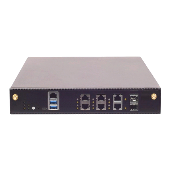
- Page 14 Chapter 1: Product Overview Description System Power System Status WWAN/WLAN Connection Status LED Indicators HDD Activity WLAN Connection Status (System) Please refer to Appendix A: LED Indicator Explanations for the description of the LED Indicators. Power Button Push to power on this device. Reset Button Software reset Mini USB Port...
- Page 15 NCA-1611 User Manual Description For safety measures to help prevent people from accidentally Grounding Point coming in contact with electrical hazards ESD Protection Screw For safety measures to help prevent people from accidentally Hole coming in contact with electrical hazards 3x Quiet Fan Power Supply 2x 12V DC in...
-
Page 16: Chapter 2: Motherboard Information
Chapter 2: Motherboard Information The block diagram indicates how data flows among components on the motherboard. Please refer to the following figure for your motherboard’s layout design. NCA-1611A NCA-1611C... - Page 17 NCA-1611 User Manual NCA-1611B NCA-1611D...
- Page 18 Chapter 2: Motherboard Information NCA-1611E...
- Page 19 NCA-1611 User Manual The motherboard layout shows the connectors and jumpers on the board. Refer to the following picture as a reference of the pin assignments and the internal connectors. JCPLD1 SATAPWR2 J80PORT1 FAN1 FAN2 FAN3 JCMOS1 JTPM1 JSATA1 JSATA2 MPCIE2 MPCIE1 JSPIROM1...
- Page 20 Chapter 2: Motherboard Information JCOMS1: Clear CMOS pin header Use the jumper setting to clear CMOS Description Description PCH_RTCRST# VCC_RTC Setting Mode Normal (Default) Clear CMOS JTPM1: TPM module pin header Supports a Trusted Platform Module (TPM) system Description Description LPC_SERIRQ LPC_FRAME# LPC_LAD0...
- Page 21 NCA-1611 User Manual JSATA1 180° SATA Connector Description Description SATA_CTX_C_DRX_P SATA_CTX_C_DRX_N SATA_DTX_CRX_N SATA_DTX_CRX_P PWR_SATA_DOM JSATA2 180° SATA Connector Description Description SATA_CTX_C_DRX_P SATA_CTX_C_DRX_N SATA_DTX_CRX_N SATA_DTX_CRX_P MPCIE1: Mini-PCIe connector Supports both 3G/4G and USB/PCIe interface adapter...
- Page 22 Chapter 2: Motherboard Information SIM Card Connector Description Description Description Description PAD1 PAD1 DATA PAD2 PAD2 MPCIE2: Mini-PCIe connector Supports Wi-Fi PCIe interface adapter SATAPWR2: SATA Power Connector Description P12V...
- Page 23 NCA-1611 User Manual J80PORT1:80 Debug port pin header Description Description CLK_33M_PORT80 LPC_LAD1_R 80PORT_RST# LPC_LAD0_R LPC_FRAME#_P80 P3V3 LPC_LAD3_P80 LPC_LAD2_P80 J16: Bypass flash jump setting pin header Description P3V3_SB CPLD_LED3 ARM Programming Selection Mode 0(1-2) Enabled (Default) 1(2-3) Disabled (default) JCOM3: Bypass flash connector Description P3V3_SB NXP_RXD...
- Page 24 Chapter 2: Motherboard Information ATX3/ATX4: ATX Power connector 4P Description Description V12A_DC_A/ V12A_DC_B V12A_DC_A/ V12A_DC_B FAN3/FAN2/FAN1: CPU Fan Description CPUFANOUT BMC_FAN_TACH0/1/2 P12V SW2: Reset button Description FP_RST_SEL SW5: Power button Description Description PWRON# PWRON# SUSLED SPRLED-...
-
Page 25: Front Panel
NCA-1611 User Manual CONN2: Power pin header Description PWRON# JSPIROM1: SPI ROM flash pin header Description Description SPI1_CS0#_DUAL P3V3_SB_SPI SPI_MISO_DUAL SPI_HOLD0_L SPI_CLK_DUAL SPI_MOSI_DUAL JRESET1: JRESET pin header for mode selection of Reset button on Front Panel Setting Mode Hardware Reset Software Reset (Default) JVGA1: VGA pin header Description... - Page 26 Chapter 2: Motherboard Information JGP1: GPIO pin Header Description Description H-SYNC V-SYNC...
- Page 27 NCA-1611 User Manual To reduce the risk of personal injury, electric shock, or damage to the unit, please remove all power connections to completely shut down the device. Also, please wear ESD protection gloves when conducting the steps in this chapter. 1.
-
Page 28: Chapter 3: Hardware Setup
Chapter 3: Hardware Setup The motherboard provides two mini-PCIe slots, with one supporting 3G/4G data transmission module and the other one supporting Wi-Fi module. 1. Locate MPCIE1 slot. 2. Align the notch of the DIMM module with the socket key in the slot. Socket Notch 3. - Page 29 NCA-1611 User Manual 4. Push down on the module and secure it with screws that come with it. 5. Snap the end of the antenna cable onto the connector on the module. Press down the golden end of the cable until it clicks into place. 6.
- Page 30 Chapter 3: Hardware Setup 1. Locate MPCIE2 slot. 2. Insert the Nano-SIM card. Make sure card’s gold contacts face downwards and the angled corner of the card is positioned correctly as shown in the picture. 3. Follow the procedures for installing a Wi-Fi supported module...
- Page 31 NCA-1611 User Manual NCA-1611 is built with one 2.5” HDD/SSD slot drive bay as well as the support for SATADOM. The following will discuss disk drive installation procedures based on their designs. 1. Locate the 2.5” disk bay area in the chassis.
-
Page 32: Internal Jumpers & Connectors
Chapter 3: Hardware Setup 5. Insert one end of the SATA data cable to the SATA contacts on the disk. Do the same to the SATA power cable. Make the two cables’ ends go under and pass through the CPU dusk cover 6. -
Page 33: Enter Bios Setup
NCA-1611 User Manual 1. Locate JTPM1 pin header. 2. Align the pins on the module with the corresponding ones on the pin header; Pin 1 is illustrated as a triangle shape. 3. Insert the module into the pin header until it is totally seated. JTPM1 4. - Page 34 Chapter 3: Hardware Setup The motherboard supports DDR4 registered DIMM memory for heavy-duty operations. Please follow the steps below to install the DIMM memory modules. 1. Locate the DIMM slot. 2. Pull open the DIMM slot latches. 3. Align the notch of the DIMM module with the socket key in the slot.
- Page 35 NCA-1611 User Manual To connect the internal 10-pin header to USB cable or 12-pin header to VGA (DB15) cable to Motherboard, make sure the pins on the cable’s head matches the corresponding ones on the header. USB cable USBA2 JVGA1 VGA cable...
- Page 36 Chapter 3: Hardware Setup With the Rackmount Kit, NCA-1611 can be fixed onto rack post along with the system’s power adapter(s). Please contact Lanner‘s sales representative for purchasing this kit. What’s in the Rackmount Kit Check the kit contents for the following items:...
- Page 37 NCA-1611 User Manual 3. Get the power adapter’s connector through the back of the holder. 4. Attach the power adapter’s connector to the power supply slot and fasten the screw lock. 5. Insert the battery into the holder. 6. Secure the adapter with the clamp using two short screws.
- Page 38 Chapter 3: Hardware Setup Installing the System to the Rack In the rack, install a shelf to support the system. 10. Hold the system with its front facing you, lift and carefully insert the system into the rack. 11. Attach the brackets to the rail rack using screws and appropriate round-hole/square-hole retainer nuts.
-
Page 39: Intelrcsetup
NCA-1611 User Manual To enter the BIOS setup utility, simply follow the steps below: 1. Boot up the system. 2. Press <Delete> during the boot-up if you connect a keyboard to this unit. But if you connect a PC to this unit through console USB/Serial connection, then press <Tab>. -
Page 40: Chapter 4: Bios Setup
Chapter 4: BIOS Setup Setup main page displays a description of BIOS information and project version information. You can also setup the System Time and System Date here. (The screenshots presented in section are for reference only) Item Description System Date Set the Date. - Page 41 NCA-1611 User Manual Use [←] / [→] to select [Advanced] setup screen. Under this screen, you may use [↑] [↓] to select an item you want to configure.
-
Page 42: Security
Chapter 4: BIOS Setup This option allows you to configure parameters regarding security device. Press “Enter“ to access the submenu. Item Value Description Security Device Enabled Enables or Disables BIOS support for the Support Disabled security device. O.S. will not show Security Device. - Page 43 NCA-1611 User Manual This option allows you to configure parameters about Super IO Chip. Press “Enter“ to access the submenu. Serial port 1 Configuration Item Value Description Serial Port Enabled Enable or Disable Serial Port 1. Disabled Device Settings IO=3F8h; IRQ = 4...
- Page 44 Chapter 4: BIOS Setup If with the case’s support, enabling this option will have the unit sound when someone opens the case of this unit, which is considered against your organization’s policy. The default is “Disabled”. Item Value Description Case Open Enabled Enable or Disable Case Open function.
- Page 45 NCA-1611 User Manual Item Value Description Disabled LAN1 LAN2 LAN3 LAN4 Control Legacy PXE Control which LAN the Legacy PXE boots LAN5 Boot from from. LAN6 LAN7 LAN8 LAN9 LAN10...
- Page 46 Chapter 4: BIOS Setup Item Value Description Status LED GREEN Configure Status LED.
- Page 47 NCA-1611 User Manual This option allows you to configure Digital I/O pin properties. Select the desired pin and press <Enter> to modify. The default is “Output Low”. Item Value Description Output Low Digital I/O Output 1 Configure Digital I/O Pin1. Output High Output Low Digital I/O Output 3...
- Page 48 Chapter 4: BIOS Setup This option allows you to configure parameters about serial port console redirection. Press “Enter “to access the submenu. The default is “Enabled”. Item Value Description COM0 Enabled Console Redirection Enable or Disable. Console Redirection Disabled...
- Page 49 NCA-1611 User Manual Console Redirection Settings: select this item to enter the setting sub-menu. These settings specify how the host computer and the remote computer will exchange data. Both computers should have the same or compatible settings. Item Value Description ANSI: Extended ASCII char set.
- Page 50 Chapter 4: BIOS Setup Mark Space Stop bits indicate the end of a serial data Stop Bits packet. None Flow control can prevent data loss from Flow Control Hardware RTS/CTS buffer overflow. VT-UTF8 Combo Key Disabled Enable VT-UTF8 Combination Key Support for Support Enabled ANSI/VT100 terminals...
- Page 51 NCA-1611 User Manual Legacy Console Redirection Setting Item Value Description COM0 Select a COM port to display redirection of Redirection COM Port COM1 Legacy OS and Legacy OPROM Messages 80x24 On Legacy OS, the Number of Rows and Resolution 80x25 Columns supported redirection When Bootloader is selected, then Legacy Console...
- Page 52 Chapter 4: BIOS Setup This option allows you to configure parameters to be programmed into PCI Latency Timer Register. Item Value Description If the system has SR-IOV capable PCIe Disabled SR-IOV Support Devices, this option Enables or Disables Enabled Single Root IO Virtualization Support.
- Page 53 NCA-1611 User Manual This option allows you to enable or disable ROM execution settings. Item Value Description Disabled CSM Support Enable/Disable CSM Support Enabled Do Not Launch Controls the execution of UEFI and Legacy Network UEFI PXE OpROM Legacy Do Not Launch Controls the execution of UEFI and Legacy Storage UEFI...
- Page 54 Chapter 4: BIOS Setup This option allows you to change USB configuration parameters. Legacy USB Support: Item Value Description Enables Legacy USB support. Enabled AUTO option disables legacy support if Legacy USB Support Disabled no USB devices are connected. Auto DISABLE option will keep USB devices available only for EFI applications.
- Page 55 NCA-1611 User Manual 1 sec 5 sec The time-out value for Control, Bulk, and USB transfer time-out 10 sec Interrupt transfers. 20 sec 1 sec Device reset 5 sec USB mass storage device Start Unit time-out 10 sec command time-out. 20 sec Maximum time the device will take before it properly reports itself to the...
- Page 56 Chapter 4: BIOS Setup Item Value Description Disabled Network Stack Enable/Disable UEFI Network Stack Enabled...
- Page 57 NCA-1611 User Manual Use [←] / [→] to select the Chipset menu item from the BIOS setup screen to enter the IntelRCSetup Setup screen. Users can select any of the items in the left frame of the screen. Item Value Description Processor Displays and provides option to change...
- Page 58 Chapter 4: BIOS Setup Item Value Description Enables Hyper Threading (Software Hyper-Threading Disabled Method to Enable/Disable Logical [ALL] Enabled Processor threads. Disabled When disabled, forces the XD feature Execute Disable Bit Enabled flag to always return 0. Disabled Enables the Vanderpool Technology, Enabled takes effect after a reboot.
- Page 59 NCA-1611 User Manual Item Value Description When enabled, OS sets CPU frequency Disabled EIST (P-states) according load. When disabled, CPU Enabled frequency is set at max non-turbo. CPU P State Control None Controls CPU frequency. CPU C State Control None Control CPU idle states CPU Advanced PM Additional CPU Power Management...
- Page 60 Chapter 4: BIOS Setup CPU C State Control Item Value Description Disabled Enables the Enhanced Cx state of the CPU C State Enabled CPU, takes effect after a reboot. Disabled Enable/Disable CPU C6 (ACPI C2) report CPU C6 report Enabled to OS Recommended to be enabled.
- Page 61 NCA-1611 User Manual Energy Perf BIAS Item Value Description Energy Performance Disabled Selects whether BIOS or Operating System Tuning Enabled chooses energy performance bias tuning. Performance Energy Performance Balanced Performance Set Energy Performance BIAS, which overrides BIAS setting. Balanced Power OS setting.
- Page 62 Chapter 4: BIOS Setup DRAM RARL Configuration Item Value Description Disabled DRAM RAPL Baseline enabled and DRAM RAPL Baseline DRAM RAPL Mode 0 baseline mode DRAM RAPL Mode 1...
- Page 63 NCA-1611 User Manual Item Value Description Disable Link L0s Enable Link L0s Enable:Disable,Enable,Auto(default) Enable Disable COD Enable Enable Enable/disable Cluster on Die. Auto Disable Early Snoop Enable Auto...
- Page 64 Chapter 4: BIOS Setup Item Value Description Auto Enforce POR Enable to enforce POR restrictions for DDR3 Enforce POR Disabled frequency and voltage programming Enforce Stretch Goals 1333 1400 1600 Maximum Memory Frequency Selections in Memory Frequency 1800 Mhz. Do not select Reserved 1867 2000 2133...
- Page 65 NCA-1611 User Manual Memory Thermal Item Value Description Memory Power Auto Configures CKE and related Memory Power Savings Mode Disabled Savings Features APD On User Defined...
- Page 66 Chapter 4: BIOS Setup Memory Map Item Value Description A7 Mode Disable A7 Mode Disable/Enable Enable...
- Page 67 NCA-1611 User Manual Item Value Description IIO0 Configuration None Press <Enter> to bring up the Intel VT for Intel VT for Directed None Directed I/O (VT-d) Configuration menu. I/O (VT-d) PCI-E ASPM Support Disable This option enables/disables the ASPM support (Global) L1 Only for all downstream devices.
- Page 68 Chapter 4: BIOS Setup IIO0 Configuration...
- Page 69 NCA-1611 User Manual Intel VT for Directed I/O (VT-d) Item Value Description Intel VT for Directed Disable Enable/Disable Intel Virtualization Technology for I/O (VT-d) Enable Directed I/O (VT-d) by reporting the I/O device assignment to VMM through DMAR ACPI Tables.
- Page 70 Chapter 4: BIOS Setup Item Value Description PCI Express None PCI Express Configuration settings Configuration PCH SATA None SATA devices and settings Configuration USB Configuration None USB Configuration Settings Security None Security Configuration Configuration Power On Restore AC Power Power Off Select S0/S5 for ACPI state after a G3 Loss Last State...
- Page 71 NCA-1611 User Manual PCI Express Configuration Item Value Description PCI-E ASPM Support Disable This option enables/disables the ASPM (Global) L1 Only support for all downstream devices. Enable PCIe root port function swapping PCIe Root Port Function Disabled feature to dynamically assign function 0 Swapping Enabled to the enabled root port.
- Page 72 Chapter 4: BIOS Setup PCI Express Root Port Item Value Description PCI-E ASPM Support Disable This option enables/disables the ASPM (Global) L1 Only support for all downstream devices. Enable PCIe root port function swapping PCIe Root Port Function Disabled feature to dynamically assign function 0 Swapping Enabled to the enabled root port.
- Page 73 NCA-1611 User Manual PCH SATA Configuration Item Value Description Disabled SATA Controller Enable or Disable SATA Controller Enabled This will configure SATA as IDE, RAID or Configure SATA as AHCI AHCI. Disabled Port 1 Enable or Disable SATA Controller Enabled Disabled Spin Up Device PCI Express Root Port 3 Settings...
- Page 74 Chapter 4: BIOS Setup USB Configuration Item Value Description Smart Auto Auto xHCI Mode Enabled Mode of operation of xHCI controller. Disabled Manual...
- Page 75 NCA-1611 User Manual Security Configuration Item Value Description Disabled Enable/Disable the PCH GPIO Lockdown GPIO Lockdown Enabled feature. Disabled Enable will lock bytes 38h-3Fh in the RTC Lock Enabled lower/upper 128-byte bank of RTC RAM Disabled Enable/Disable the PCH BIOS Lock BIOS Lock Enabled Enable feature.
- Page 76 Chapter 4: BIOS Setup...
- Page 77 NCA-1611 User Manual Use [←] / [→] to select [Security] setup screen. Under this screen, you may use [↑] [↓] to select an item you would like to configure. Administrator Password & User Password: Item Description Administrator If ONLY the Administrator's password is set, then this only limits access to Password Setup and is only asked for when entering Setup.
- Page 78 Chapter 4: BIOS Setup Secure Boot: enter Secure Boot page for more related settings. Item Value Description Secure Boot activated when Platform Disabled Key(PK) is enrolled, System mode is Enable Secure Boot Enabled User/Deployed, and CSM function is disabled Secure Boot mode selector: Standard In Custom mode, Secure Boot Variables Secure Boot Mode...
- Page 79 NCA-1611 User Manual Key Management Item Value Description Allow provision factory default Provision Factory Disabled Secure Boot keys when System is in Defaults Enabled Setup Mode. Force System to User mode – restore Restore Factory None factory default Secure Boot Default keys databases Allow the image to run in Secure Boot...
- Page 80 Chapter 4: BIOS Setup Select the Boot menu item from the BIOS setup screen to enter the Boot Setup screen. Item Value Description Number of seconds to wait for setup Setup Prompt Timeout activation key. 65535 means indefinite waiting. Bootup NumLock State Select the keyboard NumLock state Disabled Quiet Boot...
- Page 81 Select the Save and Exit menu item from the BIOS setup screen to enter the Save and Exit Setup screen. Users can select any of the items in the left frame of the screen. Save Changes and Exit When you have completed the system configuration, select this option to save the changes and Exit from BIOS Setup, so the new system configuration parameters can take effect.
- Page 82 NCA-1611 User Manual The status explanations of LED indicators on Front Panel are as follows: System Power System Status WLAN Connection Status HDD Activity Wireless Connection Status System Power Solid Green The system is powered on The system is powered off System Status This LED indicator is programmable.
-
Page 83: Appendix B: Setting Up Console Redirections
Appendix B: Setting up Console Redirections Console redirection lets you monitor and configure a system from a remote terminal computer by re-directing keyboard input and text output through the serial port. The following steps illustrate how to use this feature. The BIOS of the system allows the redirection of the console I/O to a serial port. With this configured, you can remotely access the entire boot sequence through a console port. - Page 84 Bypass Gen 3 employs a programming method to control the bypass function by software. There are typically two types of communication status for the bypass function, one is “Normal “ and another is “Bypass “ status. Furthermore, the Lanner Bypass software is capable of controlling the bypass status in the following 3 instances.
- Page 85 Appendix D: Installing Intel® LAN Controller Driver for Linux To install the Intel® LAN controller base driver for the Red Hat® and Linux operating system, please visit http://www.lannerinc.com/support/download-center/drivers, enter the product category and download the utility package. For the latest driver update, please visit Intel® download center at https://downloadcenter.intel.com/, use the keyword search or the filter to access the driver’s product page, and then download the latest controller driver as well as the ReadMe document.
-
Page 86: Rma Service
NCA-1611 User Manual 1. All products are under warranty against defects in materials and workmanship for a period of one year from the date of purchase. 2. The buyer will bear the return freight charges for goods returned for repair within the warranty period; whereas the manufacturer will bear the after service freight charges for goods returned to the user. -
Page 87: Appendix E: Terms And Conditions
Appendix E: Terms and Conditions When requesting RMA service, please fill out the following form. Without this form enclosed, your RMA cannot be processed.
Need help?
Do you have a question about the NCA-1611A and is the answer not in the manual?
Questions and answers