
Subscribe to Our Youtube Channel
Related Manuals for Lanner NCA-1513


Summary of Contents for Lanner NCA-1513
- Page 1 NCA-1513 User Manual Network Appliance Platform Hardware Platforms for Network Computing NCA-1513 User Manual Version: 1.0 Date of Release:2019-12-26...
-
Page 2: About This Document
- assumed to be qualified in the servicing of computer equipment, such as professional system integrators, or service personnel and technicians. The latest version of this document can be found on Lanner’s official website, available either through the product page or through the... -
Page 3: Technical Support
NCA-1513 User Manual Technical Support In addition to contacting your distributor or sales representative, you could submit a request to our Lanner Technical Support at http://www.lannerinc.com/technical-support where you can fill in a support ticket to our technical support department. Copyright and Trademarks This document is copyrighted ©... -
Page 4: Contact Information
Contact Information Taiwan Corporate Headquarters China Lanner Electronics Inc. Beijing L&S Lancom Platform Tech. Co., Ltd. 7F, No.173, Sec.2, Datong Rd. Xizhi District, Guodong LOFT 9 Layer No. 9 Huinan Road, New Taipei City 22184, Taiwan Huilongguan Town, Changping District, Beijing 102208 China 立端科技股份有限公司... -
Page 5: Federal Communication Commission Interference Statement
NCA-1513 User Manual Federal Communication Commission Interference Statement This equipment has been tested and found to comply with the limits for a Class B digital device, pursuant to Part 15 of FCC Rules. These limits are designed to provide reasonable protection against harmful interference in a residential installation. -
Page 6: Safety Guidelines
Safety Guidelines Follow these guidelines to ensure general safety: Keep the chassis area clear and dust-free during and after installation. Do not wear loose clothing or jewelry that could get caught in the chassis. Fasten your tie or scarf and roll up your sleeves. - Page 7 The installation of this product must be performed by trained specialists; otherwise, a non-specialist might create the risk of the system’s falling to the ground or other damages. Lanner Electronics Inc. shall not be held liable for any losses resulting from insufficient strength for supporting the system or use of inappropriate installation components.
- Page 8 attention should be given to supply connections other than direct connections to the branch circuit (e.g., use of power strips). Electrical Safety Instructions Before turning on the device, ground the grounding cable of the equipment. Proper grounding (grounding) is very important to protect the equipment against the harmful effects of external noise and to reduce the risk of electrocution in the event of a lightning strike.
- Page 9 NCA-1513 User Manual This equipment must be grounded. The power cord for product should be connected to a socket-outlet with earthing connection. Cet équipement doit être mis à la terre. La fiche d'alimentation doit être connectée à une prise de terre correctement câblée...
-
Page 10: Table Of Contents
Table of Contents Chapter 1: Product Overview ............11 Package Content ......................... 11 Optional Kits ..........................11 Ordering Information ......................... 11 System Specifications ......................... 12 Front Panel ..........................13 Rear Panel ........................... 14 Motherboard Information ......................15 Chapter 2 Hardware Installation............. 24 Installing Nano SIM Card ...................... -
Page 11: Chapter 1: Product Overview
CHAPTER 1: PRODUCT OVERVIEW NCA-1513 series is an Intel ATOM based system desktop platform, based on 4-Core CPU with max 6x GbE copper ports or 4xGbE + 2x SFP ports (by SKU). The system is targeted at low-cost desktop with ECC or Non-ECC DDR4 memory support. -
Page 12: System Specifications
Chapter 1: Product Overview System Specifications Form Factor Desktop SKU A/D: Intel Atom C3558, 2.2GHz Processor Options SKU B: Intel Atom C3308, 1.6GHz SKU C: Intel Atom C3338, 1.5GHz Platform CPU Socket 1x BGA Chipset Security Acceleration Intel® QuickAssist Technology (SKU A/B/D) BIOS AMI SPI Flash BIOS DDR4 2133MHz ECC / Non-ECC (1866MHz... -
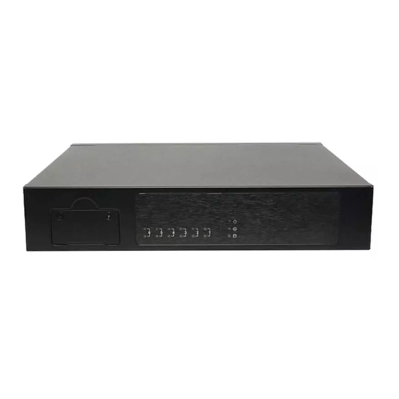
Page 13: Front Panel
NCA-1513 User Manual Front Panel Description 1x Nano SIM Slot SIM Card Slot System Power System Status LED Indicators HDD Activity LAN Ports... -
Page 14: Rear Panel
Chapter 1: Product Overview Rear Panel Description Power Switch 1x Power Button For hardware reset Reset Button DC Jack 1x DC Power Jack Console Port 1x RJ45 console port USB Port 2x USB 3.0 Port or 2x USB 2.0 Port (by SKU) 6x RJ45 Port or 2x SFP Port + 4x RJ45 Port (by SKU) Port Sequence (from left to right): 213456 LAN Port... -
Page 15: Motherboard Information
NCA-1513 User Manual Motherboard Information Block Diagram The block diagram indicates how data flows among components on the motherboard. Please refer to the following figure for your motherboard’s layout design. - Page 16 Chapter 1: Product Overview Jumper Setting and Pin Assignment The motherboard board layout shows the connectors on the board. Refer to the below picture as a reference of the pin assignments.
- Page 17 NCA-1513 User Manual BAT1: RTC Battery connector Description V_BATTERY COM1: Console port Description COM1_RTS_N COM1_DTR_N COM1_TXD LGND LGND COM1_RXD COM1_DSR_N COM1_CTS_N COMB2: Internal COM port for debug Description Description NDCD2- NDSR2- NRXD2 NRTS2- NTXD2 NCTS2- NDTR2- NRI2- IOGND2 CON1: SATA power connector...
- Page 18 Chapter 1: Product Overview CONN2: Power pin header Description PWRON# FAN2: CPU FAN Description CPUFANOUT CPUFANIN P12V_S GPIO1: GPIO connector Description Description GPO_B_1- GPI_B_1 GPO_B_2 GPI_B_2 GPO_B_3 GPI_B_3 GPO_B_4- GPI_B_4 J8: Gen3 bypass flash jumper for ARM Programming Selection 0(2- 3) : Enable 1(1-2) : Disable (default)
- Page 19 NCA-1513 User Manual JOPEN1: Case open connector Description SIO_CASEOPEN0_N JRESET1: H/W & S/W Reset :Hardware Reset :Software Reset (Default) Description FP_RST_BTN_N SW_RST_GP_N JRTC1: Clear CMOS : NORMAL : CLEAR RTC Description P3V3_RTC SOC_SRTCRST_N JRTC2: Clear CMOS : NORMAL : CLEAR RTC...
- Page 20 Chapter 1: Product Overview M2_LTE: M.2 con (Only LTE) Description Description P3V3_AUX P3V3_AUX PWROFF# USB1_SB_L_DP W_DIS# USB1_SB_L_DN UIM1_VPP1 USB3_HRX_L_DTX_N16 UIM1_RST1 USB3_HRX_L_DTX_P16 UIM1_CLK1 UIM1_DAT1 USB3_HTX_L_DRX_N16 UIM1_PWR USB3_HTX_L_DRX_P16 NGFF_LTE_RST# P1V8_A P3V3_AUX P3V3_AUX P3V3_AUX...
- Page 21 NCA-1513 User Manual M2_STORAGE: M.2 storage connector (Only Storage) Description Description P3V3_AUX P3V3_AUX SATA_HRX_C_DTX_P4 SATA_HRX_C_DTX_N4 SATA_HTX_C_DRX_N4 SATA_HTX_C_DRX_P4 NGFF_STORAGE_RST# P3V3_AUX P3V3_AUX P3V3_AUX...
- Page 22 Chapter 1: Product Overview MPCIE1: Mini PCIE 52PIN Description Description P3V3_AUX P1V5_A CLKREQ_MPCIE_SLOT2 CLK100_PCIE_SLOT1_4N CLK100_PCIE_SLOT1_4P P3V3_AUX MINI_PCI_RST# PEX_RX5N P3V3_AUX PEX_RX5P P1V5_A SMB_MPCIE_CLK PEX_TX5N_C SMB_MPCIE_DATA PEX_TX5P_C USB2_P0_DN_L USB2_P0_DP_L P3V3_AUX P3V3_AUX P1V5_A P3V3_AUX PW1: DC power connector Description P12V_SB...
- Page 23 NCA-1513 User Manual SATA1: SATA connector Description SATA_TX_DP0_C SATA_TX_DN0_C SATA_RX_DN0_C SATA_RX_DP0_C SIM2: M2_LTE SIM card slot Description Description UIM1_PWR UIM1_DAT1 UIM1_RST1 UIM1_VPP1 UIM1_CLK1 SW2: Reset Button Description Description SW_RST_GP_N SW3: Power Button Description Description PWRON# PWRON# PRLED- SUSLED-...
-
Page 24: Chapter 2 Hardware Installation
Chapter 2 Hardware Installation CHAPTER 2 HARDWARE INSTALLATION To reduce the risk of personal injury, electric shock, or damage to the equipment, please remove all power connections to completely shut down the device. Also, please wear ESD protection gloves when conducting the steps described hereafter. -
Page 25: Installing Nano Sim Card
NCA-1513 User Manual Installing Nano SIM Card The SIM slot on front panel supports an LTE module. The SIM socket supports the push-push mechanism, allowing inserting and ejecting the SIM card to be as easy as one push. 1. Loosen the two screws that secure the SIM slot cover and remove the slot cover. With the angled corner facing inward, push the SIM card all the way in until it clicks into place. -
Page 26: Mounting An Sma-Mount Antenna Cable Assembly
Chapter 2 Hardware Installation Mounting an SMA-Mount Antenna Cable Assembly To mount the Wi-Fi/LTE antennas: 1. Take out the antenna pigtail cable from the Antenna Kit. From inside the chassis, insert the SMA Female Bulkhead through the antenna hole on the panel. SMA Female Washer Bulkhead... -
Page 27: Rack-Mounting The System
NCA-1513 User Manual Rack-mounting the System With the rack mount kit, this system can be fixed onto rack posts. Please contact Lanner‘s sales representative for purchasing this kit. What’s in the Rack-mount Kit Check the kit for the following items:... - Page 28 Chapter 2 Hardware Installation Installing the System to the Rack In the rack, install a shelf to support the system (recommended). Hold the system with its front facing you, lift and carefully insert the system into the rack. Attach the brackets to the rail rack using rack-mounting screws and/or retainer nuts.
-
Page 29: Chapter 3 Software Setup
CHAPTER 3 SOFTWARE SETUP BIOS Setup BIOS is a firmware embedded on an exclusive chip on the system’s motherboard. Lanner's BIOS firmware offering including market-proven technologies such as Secure Boot and Intel Boot Guard technology deliver solid commitments for the shield protection against malware, uncertified sequences and other named cyber threats. - Page 30 Chapter 3 Software Setup Setup main page contains BIOS information and project version information. Feature Description BIOS Vendor: American Megatrends Core Version: AMI Kernel version, CRB code base, X64 BIOS Compliancy: UEFI version, PI version Information Project Version: BIOS release version Build Date and Time: MM/DD/YYYY Access Level: Administrator / User To set the Date, use <Tab>...
- Page 31 NCA-1513 User Manual Advanced Page Select the Advanced menu item from the BIOS setup screen to enter the “Advanced” setup screen. Users can select any of the items in the left frame of the screen.
- Page 32 Chapter 3 Software Setup Trusted Computing...
- Page 33 NCA-1513 User Manual Feature Options Description Enables or disables BIOS support for security device. Security Device Enabled By disabling this function, OS will not show Security Support Disabled Device. TCG EFI protocol and INT1A interface will not be available. Enabled SHA-1 PCR Bank Enables or disables SHA-1 PCR Bank.
- Page 34 Chapter 3 Software Setup Super IO Configuration...
- Page 35 NCA-1513 User Manual Serial port 1 Configuration Feature Options Description Enabled Serial Port Enables or disables Serial Port 1. Disabled Device Settings IO=3F8h; IRQ = 7...
- Page 36 Chapter 3 Software Setup Serial port 2 Configuration Feature Options Description Serial Port Enabled Enable or Disable Serial Port 2. Disabled Device Settings IO=2F8h; IRQ = 10...
- Page 37 NCA-1513 User Manual H/W Monitor...
- Page 38 Chapter 3 Software Setup Watch Dog Timer Configuration Feature Options Description Watch Dog Timer Enabled Enables or disables Watch Dog Timer function Disabled...
- Page 39 NCA-1513 User Manual Digital I/O Configuration Feature Options Description Output Low Digital I/O Output 1 Configure Digital I/O Pin1 Output High Output Low Digital I/O Output 3 Configure Digital I/O Pin3 Output High Output Low Digital I/O Output 5 Configure Digital I/O Pin5...
- Page 40 Chapter 3 Software Setup Status LED Configuration Feature Options Description Status LED GREEN Configures Status LED color...
- Page 41 NCA-1513 User Manual Serial Port Console Redirection Feature Options Description COM0 Enabled Console Enables or disables Console Redirection Disabled Redirection...
- Page 42 Chapter 3 Software Setup Console Redirection Settings Feature Options Description VT100: ASCII char set VT100 VT100+:Extends VT100 to support color, VT100+ function keys, etc. Terminal Type VT-UTF8 VT-UTF8:Uses UTF8 encoding to map ANSI Unicode chars onto 1 or more bytes ANSI: Extended ASCII char set 9600 19200...
- Page 43 NCA-1513 User Manual Hardware buffer overflow. RTS/CTS VT-UTF8 Combo Disabled Enables VT-UTF8 Combination Key Support Key Support Enabled for ANSI/VT100 terminals Disabled With this mode enabled, only text will be Recorder Mode Enabled sent. This is to capture Terminal data.
- Page 44 Chapter 3 Software Setup Console Redirection Settings Feature Options Description Redirection COM COM0 Select a COM port to display redirection of Legacy Port OS and Legacy OPROM Messages. 80x24 On Legacy OS, the Number of Rows and Resolution 80x25 Columns supported redirection. When Bootloader is selected, Legacy Console Redirection is disabled before booting to Always...
- Page 45 NCA-1513 User Manual PCI Subsystem Settings Feature Options Description Enable or Disables 64bit capable Devices to be Above 4G Disabled Decoded in Above 4G Address Space (Only if Decoding Enabled System Supports 64 bit PCI Decoding). Feature Options Description If the system has SR-IOV capable PCIe Devices, this...
- Page 46 Chapter 3 Software Setup Network Stack Configuration Feature Options Description Disabled Network Stack Enables or disables UEFI Network Stack Enabled Disabled Enables Ipv4 PXE Boot Support. If IPV4 is Ipv4 PXE Support Enabled disabled, PXE boot option will not be created. Disabled Enables Ipv4 HTTP Boot Support.
- Page 47 NCA-1513 User Manual CSM Configuration Feature Options Description Disabled CSM Support Enables or disables CSM Support Enabled Do Not Launch Controls the execution of UEFI and Legacy Network UEFI PXE OpROM Legacy Do Not Launch Controls the execution of UEFI and Legacy...
- Page 48 Chapter 3 Software Setup SDIO Configuration Feature Options Description Auto Auto Option: Access SD device in DMA mode if SDIO Access ADMA controller supports it,otherwise in PIO mode.DMA Mode SDMA Option: Access SD device in DMA mode.PIO Option: Access SD device in PIO mode..
-
Page 49: Usb Configuration
NCA-1513 User Manual USB Configuration Feature Options Description Enables Legacy USB support. Auto option disables legacy support if no Enabled Legacy USB Support Disabled USB devices are connected; Auto Disabled option will keep USB devices available only for EFI applications. - Page 50 Chapter 3 Software Setup Maximum time the device will take before it properly reports itself to the Host Auto Controller. Auto uses default value: for a Device power-up delay Manual Root port, it is 100 ms, for a Hub port the delay is taken from Hub descriptor.
- Page 51 NCA-1513 User Manual Control Legacy PXE Boot Feature Options Description Disabled Lan3 Control Legacy PXE Boot from which Control Legacy PXE Lan4 Lan. Boot From Lan5 Lan6...
- Page 52 Chapter 3 Software Setup NVME Configuration...
- Page 53 NCA-1513 User Manual IntelRCSetup Select the IntelRCSetup menu item from the BIOS setup screen to enter the Platform Setup screen. Users can select any of the items in the left frame of the screen. Feature Options Description Relax Security Disable...
- Page 54 Chapter 3 Software Setup Processor Configuration Feature Options Description Disable Enables/Disable EIST. GV3 must be EIST (GV3) Enable enable for Turbo. Enable or Disable CPU Turbo capability. Enable Turbo This option only applies to ES2 and Disable above. Disable Enable the Enhanced Cx state of the CPU, CPU C State Enable takes effect after reboot.
- Page 55 NCA-1513 User Manual L2 Prefetcher Enable Enable/Disable L2 Prefetch Disable Fast String Disable When enables, enable fast strings for Enable REP MOVS/STOS. Machine Check Disable Enable or Disable the Machine Check. Enable Execute Disable Bit Disable When disabled, forces the XD feature Enable flag to always return 0.
- Page 56 Chapter 3 Software Setup Server ME Configuration...
- Page 57 NCA-1513 User Manual North Bridge Chipset Configuration Feature Options Description Enables/Disables fast boot, which skips memory Disabled Fast Boot training and attempts to boot using fast known Enabled good configuration. Memory DDR-1600 DDR memory frequency: Frequency DDR-1867 DDR4 up to DDR-2666 DDR-2133 DDR3 up to DDR-1867.
- Page 58 Chapter 3 Software Setup South Bridge Chipset Configuration...
- Page 59 NCA-1513 User Manual SATA Configuration Feature Options Description Enable controller Enabled Enables/Disables SATA Controller if supported by Disabled current CPU sku Enabled Enables/Disables Link Power Management Disabled ALPM Enabled Enable/Disables Agresive Link Power Management Disabled Speed Limit Gen 1 Indicates the highest allowable speed of the...
- Page 60 Chapter 3 Software Setup SATA1 Configuration Feature Options Description Enable/disable port Enabled Enables/Disables SATA Controller port if Disabled supported by current cpu SKU. Hot plug Enabled Hot plug Disabled Spin up Enabled Spin up Disabled...
- Page 61 NCA-1513 User Manual M2SATA1 Configuration Feature Options Description Enable/disable port Enabled Enables/Disables SATA Controller port if Disabled supported by current cpu SKU. Hot plug Enabled Hot plug Disabled Spin up Enabled Spin up Disabled...
- Page 62 Chapter 3 Software Setup PCIE IP Configuration Feature Options Description Auto Select and force Root Complex Bifurcation Configuration regardless board or trident X4x4 detection. Bifurcation PCIE0 X4x2x2 X2x2x4 X2x2x2x2 Auto Select and force Root Complex Bifurcation Configuration regardless board or trident X4x4 detection.
- Page 63 NCA-1513 User Manual IQAT Configuration Feature Options Description IQAT Enabled Hides IQAT device from and OS. Disabled...
- Page 64 Chapter 3 Software Setup System Event Log Feature Options Description Disable System Error enabling and logging setup System Errors Enable option. Auto Disable Enable/Disable Memory Error logging Memory Elog Support Enable support Enable Parity Check Enable/Disable Parity Check Disable Enable Enable/Disable Correctable Memory...
- Page 65 NCA-1513 User Manual Enable error. Enable System Error reporting on all Disable PCIe System Error enumerated Root ports, bridges and Enable devices. Enable Parity Error reporting on all Disable PCIe Parity Error enumerated Root ports, bridges and Enable devices .
- Page 66 Chapter 3 Software Setup Security Select the Security menu item from the BIOS setup screen to enter the Security Setup screen. Users can select any of the items in the left frame of the screen. Feature Description If ONLY the Administrator's password is set, it only limits access to Setup and is only asked for when Administrator Password entering Setup.
- Page 67 NCA-1513 User Manual Secure Boot Feature Options Description Secure Boot is activated when Platform Key(PK) is Secure Boot Disabled enrolled, System mode is User/Deployed, and CSM Enable Enabled function is disabled. Customizable Secure Boot mode: In Custom mode, Standard Secure Boot Policy variables can be configured by...
- Page 68 Chapter 3 Software Setup Key Management Feature Options Description Factory Key Disabled Provision factory default keys on next re-boot only Provision Enabled when System in Setup Mode. Force System to User Mode. Configure NVRAM to Restore Factory None contain OEM-defined factory default Secure Boot keys keys.
-
Page 69: Boot Menu
NCA-1513 User Manual Boot Menu Select the Boot menu item from the BIOS setup screen to enter the Boot Setup screen. Users can select any of the items in the left frame of the screen. Feature Options Description The number of seconds to wait for setup Setup Prompt Timeout activation key. - Page 70 NCA-1513 User Manual Save and Exit Menu Select the Save and Exit menu item from the BIOS setup screen to enter the Save and Exit Setup screen. Users can select any of the items in the left frame of the screen.
- Page 71 Chapter 3 Software Setup ■ Restore Defaults Restore default values for all setup options. Select “Yes” to load Optimized defaults. The items listed under Boot Override depend on devices connected to system. Note:...
-
Page 72: Appendix A: Led Indicator Explanations
NCA-1513 User Manual APPENDIX A: LED INDICATOR EXPLANATIONS The status explanations of LED indicators on the Front Panel are as follows: Power Status System Status HDD Activity System Power Green The system is powered and running The system is powered off System Status This LED indicator is programmable. -
Page 73: Appendix B: Network Interface Renaming
Appendix B: Renaming Network Interface APPENDIX B: RENAMING NETWORK INTERFACE Prerequisite Login as “root.” Have all network interfaces disconnected. Description It requires five steps to rename system’s network interface in Linux. Scan all network-related interfaces in the system. Filter the network interfaces. Please only preserve the interface that you want to rename. Check interfaces’... - Page 74 NCA-1513 User Manual Screenshots of Renaming Procedures 1. Scan and filter.
- Page 75 Appendix B: Renaming Network Interface If any network interface is still running, the utility will exit. Renaming will start after the message shows “PASS: All interfaces are DOWN”.
- Page 76 NCA-1513 User Manual If renaming fails (using the same name), the utility will skip saving step and exit. If renaming is successful, choose a save method or just leave.
- Page 77 Appendix B: Renaming Network Interface Save successfully. You can skip saving and set AutoNaming.
-
Page 78: Appendix C: Terms And Conditions
NCA-1513 User Manual APPENDIX C: TERMS AND CONDITIONS Warranty Policy 1. All products are under warranty against defects in materials and workmanship for a period of one year from the date of purchase. 2. The buyer will bear the return freight charges for goods returned for repair within the warranty period;... -
Page 79: Rma Service Request Form
Appendix C: Terms and Conditions RMA Service Request Form When requesting RMA service, please fill out the following form. Without this form enclosed, your RMA cannot be processed.
Need help?
Do you have a question about the NCA-1513 and is the answer not in the manual?
Questions and answers