
Related Manuals for Lanner NCA-5540


Summary of Contents for Lanner NCA-5540
- Page 1 Network Appliance Platforms NCA-5540 User Manual Version: 1.0 Date of Release:2023-09-21...
- Page 2 - assumed to be qualified in the servicing of computer equipment, such as professional system integrators, or service personnel and technicians. The latest version of this document can be found on Lanner’s official website, available either through the product page or through the Lanner Download Center page with a login account and password.
- Page 3 NCA-5540 User Manual Contact Information Taiwan Corporate Headquarters China Lanner Electronics Inc. Beijing L&S Lancom Platform Tech. Co., Ltd. 7F, No.173, Sec.2, Datong Rd. Guodong LOFT 9 Layer No. 9 Huinan Road, Xizhi District, New Taipei City 22184, Huilongguan Town, Changping District, Beijing...
- Page 4 NCA-5540 User Manual Acknowledgment Intel® and Intel® Celeron® are trademarks of Intel Corporation or its subsidiaries in the U.S. and/or other countries. Microsoft Windows and MS-DOS are registered trademarks of Microsoft Corp. All other product names or trademarks are properties of their respective owners.
- Page 5 NCA-5540 User Manual Safety Guidelines Follow these guidelines to ensure general safety: Keep the chassis area clear and dust-free during and after installation. Do not wear loose clothing or jewelry that could get caught in the chassis. Fasten your tie or scarf and roll up your sleeves.
- Page 6 The installation of this product must be performed by trained specialists; otherwise, a non-specialist might create the risk of the system’s falling to the ground or other damages. Lanner Electronics Inc. shall not be held liable for any losses resulting from insufficient strength for supporting the system or use of inappropriate installation components.
- Page 7 NCA-5540 User Manual Electrical Safety Instructions Before turning on the device, ground the grounding cable of the equipment. Proper grounding (grounding) is very important to protect the equipment against the harmful effects of external noise and to reduce the risk of electrocution in the event of a lightning strike.
-
Page 8: Table Of Contents
NCA-5540 User Manual Table of Contents Chapter 1: Product Overview ............10 Package Content ......................... 10 Ordering Information ......................... 10 Optional Accessories ........................10 System Specifications ......................... 11 Front Panel ..........................12 Rear Panel ........................... 13 Motherboard Information ......................14 Chapter 2: Hardware Setup ............. - Page 9 NCA-5540 User Manual IPMI Commands Support List ..................... 54 Using BMC Web UI ........................56 Chapter 4: BIOS Setup ..............62 Main Page ........................... 63 Advanced Setup .......................... 64 Platform Setup ..........................81 Socket Configuration ........................86 Server Mgmt (SKU A / SKU B) ..................... 95 Server Mgmt (SKU C / SKU D) .....................
-
Page 10: Chapter 1: Product Overview
NCA-5540 User Manual CHAPTER 1: PRODUCT OVERVIEW The NCA-5540, a high-performance 1U rackmount network security appliance, is powered by Intel® Xeon® Processor Scalable Family (Sapphire Rapids-SP) and it delivers optimized network traffic management and enhanced virtualized network security capabilities. Package Content... -
Page 11: System Specifications
NCA-5540 User Manual System Specifications Form Factor 1U 19” Rackmount Processor Options Intel® Xeon® Processor Scalable Family (Sapphire Rapids-SP) SKU A/C: 300W; CPU TDP SKU B/D: 225W Platform CPU Socket 1x LGA4677 Chipset Intel® Emmitsburg PCH Security Acceleration Intel® QuickAssist Technology... -
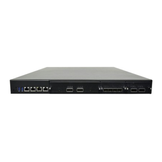
Page 12: Front Panel
NCA-5540 User Manual Front Panel Description Reset button 1x Reset Button System Power LED Indicators System Status HDD/SSD Activity USB Ports 2x USB 3.0 LAN Port 2x RJ45 port LOM Port 1x LOM Port (via BMC Card) Console Port 1x Console Port... -
Page 13: Rear Panel
NCA-5540 User Manual Rear Panel Description Ground Hole 1x Ground screw hole Power Switch 1x Power Switch I/O Button Fans 5x Smart Fans ESD Jack 1x ESD screw hole Alarm Reset 1x Alarm Reset Button 2x 1300W AC 1+1 Redundant CRPS Power Supply (Default);... -
Page 14: Motherboard Information
NCA-5540 User Manual Motherboard Information Block Diagram The block diagram indicates how data flows among components on the motherboard. - Page 15 NCA-5540 User Manual Internal Jumpers and Connectors The pin headers on the motherboard are often associated with important functions. With the shunt (Jumper) pushed down on the designated pins (the pin numbers are printed on the circuit board, surrounding the pin header), certain feature can be enabled or disabled.
- Page 16 NCA-5540 User Manual...
- Page 17 NCA-5540 User Manual...
- Page 18 NCA-5540 User Manual JESPI1: ESPI CS1# Flow (ESPI Mode) Pin No. Description CS1# To BMC (Default) CS1# To ESPI CONN JMERCVR1: ME FW Update Pin No. Description Normal (Default) ME Force Update JCLRPAS1: Password Clear Pin No. Description Normal (Default)
- Page 19 NCA-5540 User Manual JFOR_PWRON1: Force PWRON Options Pin No. Description Disable (Default) Enable J13: BIOS Boot Up Select Pin No. Description Force Boot Up from BIOS1 (Default) Force Boot Up from BIOS2 J12: Disable Dual BIOS Function Pin No. Description...
- Page 20 NCA-5540 User Manual JGP1: GPIO1 Conn Pin No. Description Pin No. Description GPO_B_1 GPI_B_1 GPO_B_2 GPI_B_2 GPO_B_3 GPI_B_3 GPO_B_4 GPI_B_4 JATX11 Pin No. Description Pin No. Description +P12V +P12V +P12V +P12V +P12V JATX7 Pin No. Description Pin No. Description +P12VS_PCIe_A...
- Page 21 NCA-5540 User Manual JCOM1 Pin No. Description Pin No. Description COM2_DCD# COM2_DSR# COM2_RX COM2_RTS COM2_TX COM2_CTS# COM2_DTR COM2_RI# JSPI_TPM1 Pin No. Description Pin No. Description SPI_HD1# SPI_CS1# SPI_CS0# +P3V3_SPI_PCH_AUX SPI_MISO_TPM HEADER_SPI_PCH_IO3 SPI_CLK_TPM SPI_MOSI_TPM IRQ_TPM_SPI#_R SPI_TPM_CS0# RST_PLTRST_PLD_B_N JLCM1 Pin No. Description...
- Page 22 NCA-5540 User Manual JPMB1 Pin No. Description +P3V3_AUX_PSU FM_PS_EN_PSU_N PWRGD_PS_PWROK PMBUS_CLK_PSU_R PMBUS_DAT_PSU_R PMBUS_ALERT#_R JVGA1 Pin No. Description Pin No. Description DAC_RO DAC_GO DAC_BO HSYNC_O VSYNC_O DDC_DATA DDC_CLK JPLD1 Pin No. Description +P3V3_AUX JTAG_PLD_TDO JTAG_PLD_TDI JTAG_PLD_TMS JTAG_PLD_TCK JBMC_SGPIO1 Pin No. Description...
- Page 23 NCA-5540 User Manual JIPMB1 Pin No. Description SMB_IPMB_STBY_CMOS_ISO_SDA SMB_IPMB_STBY_CMOS_ISO_SCL +P5V_AUX JATX1, JATX2, JATX3, JATX4, JATX5, JATX6 Pin No. Description Pin No. Description +P3V3 +P12V JBMC_UART1 Pin No. Description +P3V3_AUX BMC_UART5_RX BMC_UART5_TX...
-
Page 24: Chapter 2: Hardware Setup
NCA-5540 User Manual CHAPTER 2: HARDWARE SETUP To reduce the risk of personal injury, electric shock, or damage to the system, please remove all power connections to shut down the device completely and wear ESD protection gloves when handling the installation steps. -
Page 25: Installing The Cpu
NCA-5540 User Manual Installing the CPU Please note that the system delivered to you includes the heatsink and processor. This processor comes with a rather sophisticated design, therefore, the assembly of which must be handled with exclusive tools and extreme care by professionals. - Page 26 NCA-5540 User Manual When handling heatsink, always grip it along the axis of the fins of the Heatsink heatsink to avoid fin damage. Fins or soldering of fins might be damaged (1U) by handling heatsink holding along the long side of the heatsink.
- Page 27 NCA-5540 User Manual 2. Using both hands place the thumbs on the side of the carrier at the opposite end of the TIM brake lever. Push down on one side at a time slightly pressing in the outward motion until a snap sound is heard.
- Page 28 NCA-5540 User Manual 2. Turn the heatsink over and set the Anti-Tilt wires to the locked position (outward position). 3. Align Pin 1 indicator of Processor carrier and corner cut out of Heatsink. If there are two corners cut out, either orientation is fine.
- Page 29 NCA-5540 User Manual 6. If carrier latching features do not latch the heatsink properly, engage each latching Click features by pressing the heatsink at the unlatched corner. You may hear a clicking sound when latched. System Assembly PHM to Motherboard 1.
- Page 30 NCA-5540 User Manual 4. Then turn the PHM right side up. Line up PIN1 corner of the PHM to the bolster plate PIN1 corner. Lower the PHM vertically down over the bolster plate studs. 5. Set all four Anti-Tilt wires into the locked position (outward position.)
-
Page 31: Installing The System Memory
NCA-5540 User Manual Installing the System Memory The motherboard supports DDR5 registered DIMM memory for heavy-duty operations. Please follow the steps below to install the DIMM memory modules. The CPU have 12 DIMM sockets (6 on each sides) Supported Capacities: 8/16/32/64 GB ⚫... - Page 32 NCA-5540 User Manual Sapphire Rapids DDR5 Only DIMM Configurations Diagram Memory Module Installation Instructions Please follow the steps below to install the DIMM memory modules. 1. Power off the system. 2. Pull open the DIMM slot latches. 3. Align the notch of the DIMM module with the socket key in the slot.
-
Page 33: Installing Tpm Module (Optional)
NCA-5540 User Manual Installing TPM Module (Optional) The motherboard provides one TPM slot. Follow the procedures below for installing a TPM module. 1. Power off the system and open the chassis cover. 2. Locate the TPM slot on the motherboard. -
Page 34: Installing Ipmi Module (Optional)
NCA-5540 User Manual Installing IPMI Module (Optional) The system provides one IPMI slot for remote monitoring expansion. Follow the procedures below for installation. 1. Power off the system and open the chassis cover. 2. Locate the IPMI socket on the motherboard. -
Page 35: Installing The M.2 Sata Storage (Optional)
NCA-5540 User Manual Installing the M.2 SATA Storage (Optional) NCA-5540 comes with an additional M.2 storage card slot. Please follow the steps for installation. 1. Power off the system and open the chassis cover 2. Locate slot motherboard. 3. Align the notch of the M.2 memory card with the socket key in the pin slot. -
Page 36: Installing The M.2 Nvme Storage (Optional)
NCA-5540 User Manual Installing the M.2 NVMe Storage (Optional) NCA-5540 comes with two additional M.2 NVMe storage card slot. Please follow the steps for installation. 1. Power off the system and open the chassis cover. 2. Locate and unscrew four (4) screws on the fan hood/shroud, and three (3) screws on the cover. - Page 37 NCA-5540 User Manual 5. Insert the M.2 storage card pins at 30 degrees into the socket until it is fully seated. 6. Push down on the module and secure it with a screw. 7. Repeat steps if installing a second...
-
Page 38: Installing The Disk Drive(S)
NCA-5540 User Manual Installing the Disk Drive(s) NCA-5540 is built with two 2.5” HDD/SSD slot drive bay. Please follow the steps for installation. 1. Power off the system and open the chassis cover. 2. Locate the 2.5” disk bay. 3. Loosen the three (3) screws that fixes the disk tray onto the motherboard. - Page 39 NCA-5540 User Manual 5. Screw in the hard disk on both sides (two (2) screws on each side). 6. Install the tray back to the original position on the motherboard and secure with the three (3) screws. 7. Connect the SATA cable and SATA...
-
Page 40: Installing The Lcm Module (Optional)
NCA-5540 User Manual Installing the LCM Module (Optional) NCA-5540 comes with module slots for LCM module expansion. Please follow the steps below for installation. 1. The LCM module package consists of: 1x LCM Panel 1x LCM connector cable 2x screws... - Page 41 NCA-5540 User Manual 6. Install the LCM module into the module slot. 7. Insert the connector cable into the connector pin. 8. Secure the LCM module using the two (2) screws. Close the top cover of the system. The LCM module has been...
-
Page 42: Installing The Nic Modules
NCA-5540 User Manual Installing the NIC Modules NCA-5540 comes with NIC Ethernet module slots for network bandwidth expansion. Please follow the steps for installation. 1. Power off the system and open the chassis cover. 2. On the front panel, select a NIC module slot. -
Page 43: Replacing The Cooling Fans
NCA-5540 User Manual Replacing the Cooling Fans Cooling fans may wear down eventually. Please refer to the steps below for replacing cooling fans. When using a new cooling fan, just reverse the steps to install the fan back onto the enclosure and the system. - Page 44 NCA-5540 User Manual Replacing the AC Power Supply Units Power supply units wear down eventually. Please be noted that the NCA-5540 supports1300W PSU. Please prepare the power supply units matching this capacity. 1. On the rear panel, locate the power supply units and disconnect the power cords.
-
Page 45: Mounting The System
NCA-5540 User Manual Mounting the System There are two methods for installing this system into a rack: With Mounting Ear Brackets only This method is quick and easy by fixing this system to the front posts of the rack, but it also makes servicing the system more difficult. - Page 46 NCA-5540 User Manual Installing the System Using Mounting Ear Brackets Only 1. Check the accessory pack for the following items: 1x Screw Pack 2x Ear Brackets Screw Pack Ear Brackets 2. Align the bracket to the side of the chassis and...
- Page 47 NCA-5540 User Manual Installing the System Using the Slide Rail Kit (with Mounting Ear Brackets) 1. Check the package contents of the Slide Rail Kit. The kit shall include the following items: 1x pack of M4X4L screws (for 7.1 Round Hole Screws...
- Page 48 NCA-5540 User Manual 5. Align the bracket to the side of the chassis and make sure the screw- holes are matched, and then secure the bracket onto the chassis with three provided M4X4L screws. Align the screws with the holes indicated on the brackets and the screw holes on the side of the chassis.
- Page 49 NCA-5540 User Manual 9. For the rear rack installation, slide the rail to aim and engage the bolts on the rail’s rear end with the two available holes on the post, and the rail assembly will click into place. Click 10.
- Page 50 NCA-5540 User Manual 12. While pushing in the system, also push and hold the Rail Lock tab on both brackets. Rail Lock Push the system all the way in until it stops. To remove the system from the rack, gently pull it outwards, towards you, while pushing the Release Tab on both sides of the brackets.
-
Page 51: Chapter 3: Remote Server Management (Sku C/Sku D)
NCA-5540 User Manual CHAPTER 3: REMOTE SERVER MANAGEMENT (SKU C/SKU D) BMC Overview This document specifies the BMC firmware features. The BMC firmware implements IPMI 2.0 based on ASPEED service processor. It performs all the BMC management tasks defined by IPMI 2.0. -
Page 52: Firmware Functional Description
NCA-5540 User Manual Firmware Functional Description System health monitoring The BMC implements system sensor monitoring feature. It could monitor voltage, temperature and current of critical components. System Power Management The BMC implements chassis power and reset functions for system administrators to control and manage the system power behavior. - Page 53 NCA-5540 User Manual User Management The BMC supports 9 IDs for IPMI user accounts. The maximum length of the username and password are 16 and 20 respectively, and the possible privilege levels are Callback, User, Operator, and Administrator. Moreover, the account creator can enable/disable the user account at any time. If not specified, the default...
-
Page 54: Ipmi Commands Support List
NCA-5540 User Manual IPMI Commands Support List COMMANDS NETFN IPM Device “Global” Commands Get Device ID APP (06h) Cold Reset APP (06h) Warm Reset APP (06h) Get Device GUID APP (06h) BMC Watchdog Timer Commands Reset Watchdog Timer APP (06h) - Page 55 NCA-5540 User Manual Get SEL Entry Storage (0Ah) Delete SEL Entry Storage (0Ah) Clear SEL Storage (0Ah) Get SEL Time Storage (0Ah) Set SEL Time Storage (0Ah) Get SEL Time UTC Offset Storage (0Ah) Set SEL Time UTC Offset Storage (0Ah)
-
Page 56: Using Bmc Web Ui
NCA-5540 User Manual Using BMC Web UI In the address bar of your Internet browser, input the IP address of the remote server to access the BMC interface of that server. Initial access of BMC prompts you to enter the User Name and Password. A screenshot of the login screen... - Page 57 NCA-5540 User Manual Default User Name and Password Username: admin Password: admin The default username and password are in lower-case characters. When you log in using the default username and password, you will get full administrative rights, and it will ask you to change the default password once you log in.
- Page 58 NCA-5540 User Manual First Time Wizard After the first-time login, you will see first time wizard welcome page as the following picture. Please press the “Next” button and configure your BMC step by step. On the “IPv4”, “IPv6” and “DNS” pages, you could specify the hostname and network settings of BMC.
- Page 59 NCA-5540 User Manual Web UI Layout The BMC Web UI consists of various menu items: Menu Bar The menu bar displays the following: Dashboard Appliance – FRU Information Appliance – Sensor Reading Appliance – Event Log Appliance – Remote Media Settings Appliance –...
- Page 60 NCA-5540 User Manual A screenshot of the menu bar is shown below: Menu Bar Quick Button and Logged-in User The user information and quick buttons are located at the top right of the Web UI. User Information Logged-in user information: Click the icon to view the logged-in user information.
- Page 61 NCA-5540 User Manual The logged-in user information shows the logged-in user’s username, privilege, with the quick buttons allowing you to perform the following functions: Refresh: Click the icon to reload the current page. Sign out: Click the icon to log out of the Web UI.
-
Page 62: Chapter 4: Bios Setup
NCA-5540 User Manual CHAPTER 4: BIOS SETUP The system has AMI BIOS built-in, with a SETUP utility that allows users to configure required settings or to activate certain system features. Pressing the <Tab> or <DEL> key immediately allows you to enter the Setup Utility. -
Page 63: Main Page
NCA-5540 User Manual Main Page Setup Main Page contains BIOS information and project version information. (The screenshots presented in this section are for reference only) Item Description BIOS Vendor: American Megatrends Core Version: AMI Kernel version, CRB code base, X64... -
Page 64: Advanced Setup
NCA-5540 User Manual Advanced Setup Select the Advanced menu item from the BIOS setup screen to enter the “Advanced” setup screen. Users can select any of the items in the left frame of the screen. - Page 65 NCA-5540 User Manual Trusted Computing Feature Option Description Enables or disables BIOS support for security device. By Enabled Security Device Support disabling this function, OS will not show Security Device. Disabled TCG EFI protocol and INT1A interface will not be available.
- Page 66 NCA-5540 User Manual Trusted Computing (TPM2.0) Feature Options Description Enables or disables BIOS support for security device. By Security Device Enabled disabling this function, OS will not show Security Device. Support Disabled TCG EFI protocol and INT1A interface will not be available.
- Page 67 NCA-5540 User Manual Enabled Platform Hierarchy Enables or disables Platform Hierarchy. Disabled Enabled Storage Hierarchy Enables or disables Storage Hierarchy. Disabled Endorsement Enabled Enables or disables Endorsement Hierarchy. Hierarchy Disabled Physical Presence Select to tell OS to support PPI Spec Version 1.2 or 1.3.
- Page 68 NCA-5540 User Manual NCT7904D HW Monitor Feature Description CPU Temp This value reports the CPU temperature SYS1 Temp This value reports the System temperature SYS2 Temp This value reports the System temperature (Close CPU) FAN1A Speed This value reports the Fan1A speed...
- Page 69 NCA-5540 User Manual FAN4A Speed This value reports the Fan4A speed FAN4B Speed This value reports the Fan4B speed 1V5V This value reports the 1.05V Input voltage VDIMM This value reports the Memory Input voltage CPU VCORE This value reports the CPU VCORE Input voltage...
- Page 70 NCA-5540 User Manual Smart Fan Mode Configuration Feature Option Description Full Speed Mode Fan Out Mode Fan Mode Select Smart Fan Mode...
- Page 71 NCA-5540 User Manual F81804 Super IO Configuration...
- Page 72 NCA-5540 User Manual Serial Port 1 Configuration Feature Option Description Disabled Serial Port Enable or Disable Serial Port (COM) Enabled Device Settings IO=3F8h; IRQ=4;...
- Page 73 NCA-5540 User Manual Serial Port 2 Configuration Feature Option Description Disabled Serial Port Enable or Disable Serial Port (COM) Enabled Device Settings IO=2F8h; IRQ=3;...
- Page 74 NCA-5540 User Manual Console Redirection Settings Feature Option Description VT100: ASCII char set VT100 VT100+: Extends VT100 to support color, function keys, etc. VT100+ VT-UTF8: Uses UTF8 encoding to map Unicode chars onto Terminal Type VT-UTF8 1 or more bytes...
- Page 75 NCA-5540 User Manual Disabled With this mode enabled, only text will be sent. This is to Recorder Mode Enabled capture Terminal data. Disabled Resolution 100x31 Enables or disables extended terminal resolution Enabled VT100 LINUX XTERM86 Putty Keypad Selects Function Key and Keypad on Putty.
- Page 76 NCA-5540 User Manual PCI Subsystem Settings Feature Option Description Enables or disables 64bit capable Devices to be Enabled Above 4G Decoding Decoded in Above 4G Address Space (Only if System Disabled Supports 64 bit PCI Decoding) If the system has SR-IOV capable PCIe Devices, this...
- Page 77 NCA-5540 User Manual USB Configuration Feature Option Description Enables Legacy USB support. Enabled Auto option disables legacy support if no USB devices are connected; Legacy USB Support Disabled Disabledoption will keep USB devices available only for EFI Auto applications. Enabled This is a workaround for OSes without XHCI hand-off support.
- Page 78 NCA-5540 User Manual Network Stack Redirection Feature Option Description Disabled Network Stack Enables or disables UEFI Network Stack Enabled Disabled Enables Ipv4 PXE Boot Support. If IPV4 is disabled, PXE boot option will Ipv4 PXE Support not be created. Enabled Disabled Enables Ipv4 HTTP Boot Support.
- Page 79 NCA-5540 User Manual NVMe Configuration...
- Page 80 NCA-5540 User Manual Control PXE Boot Feature Option Description Disabled Control PXE Boot Control PXE Boot from which Lan Lan1 Lan2...
-
Page 81: Platform Setup
NCA-5540 User Manual Platform Setup Select the Platform menu item from the BIOS setup screen to enter the Platform Setup screen. Users can select any of the items in the left frame of the screen. Feature Option Description PCH Configuration... - Page 82 NCA-5540 User Manual PCH-IO Configuration Item Option Description PCH sSATA Configuration None sSATA devices and settings...
- Page 83 NCA-5540 User Manual PCH sSATA Configuration...
- Page 84 NCA-5540 User Manual Feature Option Description Disabled SATA Configuration Enables or disables SATA Controller Enabled AHCI SATA Mode Selection This will configure SATA as RAID or AHCI. RAID Disabled SATA Port 0/2/3/4/5 Enable or Disable SATA Port Enabled Disabled Hot Plug 0/2/3/4/5 Designates this port as Hot Pluggable.
- Page 85 NCA-5540 User Manual Server ME Configuration...
-
Page 86: Socket Configuration
NCA-5540 User Manual Socket Configuration Select the Socket menu item from the BIOS setup screen to enter the Socket Setup screen. Users can select any of the items in the left frame of the screen. Feature Option Description Processor None... - Page 87 NCA-5540 User Manual Processor Configuration Feature Option Description Enables Logical processor (Software Method to Enable/Disable ALL LPs Enable LP(Global) Single LP Logical Processor threads). Disabled Machine Check Enable or Disable the Machine Check Enabled Disabled Hardware Prefetcher = MLC Streamer Prefetcher (MSR 1A4h Bit[0])
- Page 88 NCA-5540 User Manual CPU Socket0 Configuration Feature Option Description 0: Enable all cores. FFFFFFFFFFF: Disable all cores least Disable Bitmap one core per CPU must be enabled. Disabling all cores is (Hex) an invalid configuration.
- Page 89 NCA-5540 User Manual Memory Configuration Feature Option Description Auto 3200 3600 Memory 4000 Maximum Memory Frequency Selections in Mhz. Do not select Frequency 4400 Reserved 4800 5200 5600 Memory Topology None Displays memory topology with DIMM population information...
- Page 90 NCA-5540 User Manual IIO Configuration Feature Option Description Socket0 Configuration None None Intel® VT for Press <Enter> to bring up the Intel? VT for Directed I/O None Directed I/O (VT-d) (VT-d) Configuration menu. PCI-E ASPM Disable This option Disable/ Per-Port the ASPM support for all...
- Page 91 NCA-5540 User Manual Socket0 Configuration Feature Option Description Port DMI None Settings related to PCI Express Port DMI Port 1A None Settings related to PCI Express Port 1A Port 1E None Settings related to PCI Express Port 1E Port 2A...
- Page 92 NCA-5540 User Manual Advanced Power Management Configuration Feature Option Description CPU P State Control None P State Control Configuration Sub menu, include Turbo, XE, etc. CPU C State Control None CPU C State Settings...
- Page 93 NCA-5540 User Manual CPU P State Control Feature Option Description Disabled SpeedStep (Pstates) Enables or disables EIST (P-States) Enabled Max Performance Boot Performance Select the performance state that the BIOS will set Max Efficient Mode before OS hand off. Set by Intel Node Manager...
- Page 94 NCA-5540 User Manual CPU C State Control Feature Option Description Disabled CPU C1 auto demotion Autonomous Core C-State Control Enabled Disabled Enhanced Halt State (C1E) Core C1E auto promotion Control. Takes effect after reboot. Enabled...
-
Page 95: Server Mgmt (Sku A / Sku B)
NCA-5540 User Manual Server Mgmt (SKU A / SKU B) Use [→] or [←] to select [Server Mgmt] setup screen. Under this screen, you may use [↑] [↓] to select an item you want to configure. Feature Option Description BMC Support Disabled This platform (SKU) doesn't support BMC. -
Page 96: Server Mgmt (Sku C / Sku D)
NCA-5540 User Manual Server Mgmt (SKU C / SKU D) Use [→] or [←] to select [Server Mgmt] setup screen. Under this screen, you may use [↑] [↓] to select an item you want to configure. Feature Option Description Enabled BMC Support Enable or disables interfaces to communicate with BMC. - Page 97 NCA-5540 User Manual OS Wtd Timer Configure the length of the OS Boot Watchdog Timer. Not available if 10 minutes Timeout OS Boot Watchdog Timer is disabled. OS Wtd Timer Configure how the system should respond if the OS Boot Watchdog...
- Page 98 NCA-5540 User Manual System Event Log (SKU C/SKU D) Use this option to change the SEL event log configuration. Feature Option Description Disabled Enables or disables all features of System Event SEL Components Logging during boot. Enabled Erase SEL Choose options for erasing SEL.
- Page 99 NCA-5540 User Manual BMC Network Configuration (SKU C/SKU D) This option allows you to configure BMC network parameters.
- Page 100 NCA-5540 User Manual Feature Option Description Unspecified Select to configure LAN channel parameters statically or Configuration Static dynamically (by BIOS or BMC). The unspecified option will Address source DynamicBmcDhcp not modify any BMC network parameters during BIOS DynamicBmcNonDhcp phase.
- Page 101 NCA-5540 User Manual View System Event Log (SKU C/SKU D) This option allows you to view the System Event Log Records.
-
Page 102: Security Setup
NCA-5540 User Manual Security Setup Select the Security menu item from the BIOS setup screen to enter the Security Setup screen. Users can select any of the items in the left frame of the screen. Feature Description If ONLY the Administrator's password is set, it only limits access to Administrator Password Setup and is only asked for when entering Setup. - Page 103 NCA-5540 User Manual Secure Boot This option allows you to customize Secure Boot settings. Feature Option Description Secure Boot is activated when Platform Key (PK) is Disabled Secure Boot enrolled, System mode is User/Deployed, and CSM Enabled function is disabled.
- Page 104 NCA-5540 User Manual Key Management Feature Option Description Factory Key Disabled Provision factory default keys on next re-boot only when Provision Enabled System in Setup Mode. Restore Factory Force System to User Mode. Configure NVRAM to contain None keys OEM-defined factory default Secure Boot keys.
-
Page 105: Boot Setup
NCA-5540 User Manual Boot Setup Select the Boot menu item from the BIOS setup screen to enter the Boot Setup screen. Users can select any of the items in the left frame of the screen. Item Option Description Setup Prompt... -
Page 106: Save And Exit Setup
NCA-5540 User Manual Save and Exit Setup Select the Save and Exit menu item from the BIOS setup screen to enter the Save and Exit Setup screen. Users can select any of the items in the left frame of the screen. - Page 107 NCA-5540 User Manual ■ Restore Defaults Restore default values for all setup options. Select “Yes” to load Optimized defaults. Note: The items under Boot Override may not be the same images, it would depend on devices connected on the system.
-
Page 108: Appendix A: Led Indicator Explanations
NCA-5540 User Manual APPENDIX A: LED INDICATOR EXPLANATIONS System Power / Status / HDD Activity The status explanations of LED indicators on Front Panel are as follows: Green: System Power Red/Green: System Status Amber: HDD Activity COLOR LED ACTION DESCRIPTION... -
Page 109: Appendix B: Dual Bios Introduction
To provide increased flexibility and usage protection, Lanner has released the 2nd Gen Dual BIOS function on Lanner appliances. With 2nd Gen Dual BIOS, both the primary BIOS and secondary BIOS can be updated and flashed using the BIOS Tool to run different versions of BIOS ROMS independently for maximum compatibility. - Page 110 Lanner Technical Support. Warning DO NOT power off or reset the system during BIOS updating process. Disclaimer Under no circumstances will Lanner accept responsibility or liability for damages of any kind whatsoever resulting or arising directly or indirectly from a BIOS update.
-
Page 111: Appendix C: Redundant Power Module Behavior
NCA-5540 User Manual APPENDIX C: REDUNDANT POWER MODULE BEHAVIOR Define Alarm and Mute behavior Power Module Power Module Power Cord Fail Remove Remove Buzzer Alarm Alarm Alarm Change back the PSU Module Put back the PSU Module Plug-in the Power cord... -
Page 112: Appendix D: Fan Sequence
NCA-5540 User Manual APPENDIX D: FAN SEQUENCE Define the Sequence of the Fan Fan Sequence – The detection is from the left to the right side, from the bottom to the top side. Example:... -
Page 113: Appendix E: Smart Power And Reset Button
NCA-5540 User Manual APPENDIX E: SMART POWER AND RESET BUTTON Smart Power and Reset Button – Control by CPLD Reset Button Power Button... -
Page 114: Appendix F: Esd/Surge Enhancement
NCA-5540 User Manual APPENDIX F: ESD/SURGE ENHANCEMENT Electrostatic Discharge (ESD): Contact IEC-61000-4-2 Discharge Discharge Level 1 ±2 kV ±2 kV Level 2 ±4 kV ±4 kV 4K Contact (Default) Level 3 ±6 kV ±8 kV 8K Air (Default) Level 4 (TBD) ±8 kV... -
Page 115: Appendix G: Terms And Conditions
NCA-5540 User Manual APPENDIX G: TERMS AND CONDITIONS Warranty Policy 1. All products are under warranty against defects in materials and workmanship for a period of one year from the date of purchase. 2. The buyer will bear the return freight charges for goods returned for repair within the warranty period;... - Page 116 NCA-5540 User Manual RMA Service Request Form When requesting RMA service, please fill out the following form. Without this form enclosed, your RMA cannot be processed.
Need help?
Do you have a question about the NCA-5540 and is the answer not in the manual?
Questions and answers