
Subscribe to Our Youtube Channel
Related Manuals for Lanner NCA-4210


Summary of Contents for Lanner NCA-4210
- Page 1 NCA-4210 User Manual NCA-4210 User Manual Version: 1.9 Date of Release:2023-11-15...
- Page 2 - assumed to be qualified in the servicing of computer equipment, such as professional system integrators, or service personnel and technicians. The latest version of this document can be found on Lanner’s official website, available either through the product page or through the Lanner Download Center page with a login account and password.
- Page 3 NCA-4210 User Manual Taiwan Corporate Headquarters China Lanner Electronics Inc. Beijing L&S Lancom Platform Tech. Co., Ltd. 7F, No.173, Sec.2, Datong Rd. Guodong LOFT 9 Layer No. 9 Huinan Road, Xizhi District, New Taipei City 22184, Huilongguan Town, Changping District, Beijing...
- Page 4 NCA-4210 User Manual Intel® and Intel® Xeon® are trademarks of Intel Corporation or its subsidiaries in the U.S. and/or other countries. Microsoft Windows and MS-DOS are registered trademarks of Microsoft Corp. All other product names or trademarks are properties of their respective owners.
- Page 5 NCA-4210 User Manual Portez des lunettes de sécurité pour protéger vos yeux. N’effectuez aucune action qui pourrait créer un danger pour d’autres ou rendre l’équipement dangereux. Coupez complètement l’alimentation en éteignant l’alimentation et en débranchant le cordon d’alimentation avant d’installer ou de retirer un châssis ou de travailler à proximité de sources d’alimentation.
- Page 6 The installation of this product must be performed by trained specialists; otherwise, a non-specialist might create the risk of the system’s falling to the ground or other damages. Lanner Electronics Inc. shall not be held liable for any losses resulting from insufficient strength for supporting the system or use of inappropriate installation components.
- Page 7 NCA-4210 User Manual Before turning on the device, ground the grounding cable of the equipment. Proper grounding (grounding) is very important to protect the equipment against the harmful effects of external noise and to reduce the risk of electrocution in the event of a lightning strike. To uninstall the equipment, disconnect the ground wire after turning off the power. A ground wire is required and the part connecting the conductor must be greater than 4 mm2 or 10 AWG.
- Page 8 NCA-4210 User Manual Main Features ..........................10 Package Content ......................... 10 Ordering Information ......................... 11 System Specifications ......................... 12 Front Panel ..........................13 Rear Panel ........................... 14 Block Diagram ..........................15 Motherboard Layout ........................16 Opening the Chassis ........................22 Installing the CPU ........................
- Page 9 NCA-4210 User Manual Boot Menu ..........................72 Save and Exit Menu ........................73 Warranty Policy .......................... 82...
- Page 10 NCA-4210 User Manual Thank you for choosing NCA-4210. The internal core of NCA-4210 is the 6th generation Intel® 14nm microprocessor, the new LGA 1151 socket, DDR4 memory support and the I/O boosting, comprehensive Intel® H110 and C236 series chipset, and flexible LAN configurations. The adoption of the 6th generation Intel®...
- Page 11 NCA-4210 User Manual SKU No. Description Intel® PCH H110 with 2x DDR4 UDIMM, 6x RJ45 (2 Pairs Bypass), 1x Slim-type NIC NCA-4210A Module (PCIEX8 only) Intel® PCH C236 with 2x DDR4 ECC DIMM 16G/DIMM, 6x RJ45 (2 Pairs Bypass), 2x 1G...
- Page 12 NCA-4210 User Manual Form Factor 1U 19” Rackmount Intel® Core™ i7-6700/i5-6500/i3/Pentium Series processor Processor Options (codename Skylake) Intel® H110 or C236 Platform Socket LGA1151 CPU TDP Approx. 65W Super I/O NCT6776 AMI SPI Flash BIOS: Support PXE function BIOS ...
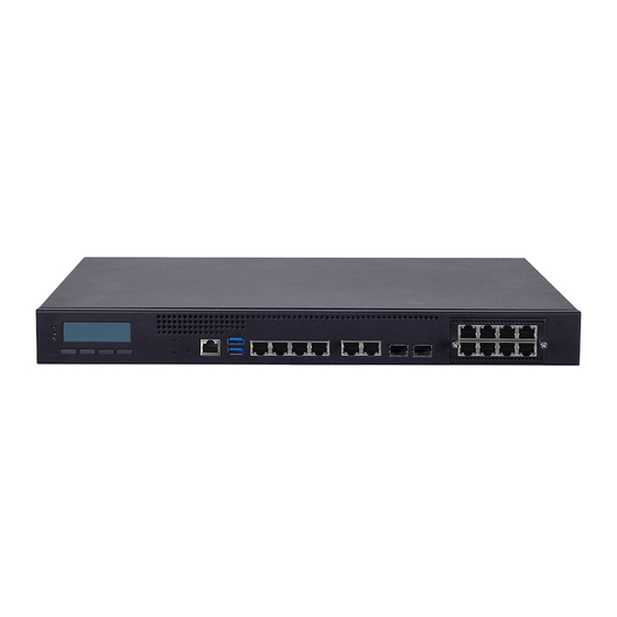
- Page 13 NCA-4210 User Manual Description System Power LED Indicators System Status HDD Activity LCM with 4x Keypads Console Port 1x RJ45 Console Port USB Port 2x USB 3.0 Type-A Ports LAN Port 6x RJ45 GbE Ports SFP Port 2x SFP LAN Ports (SKUB Only)
- Page 14 NCA-4210 User Manual Description PCIe Expansion 2x PCIe Expansion slot (Optional) Smart Fan 2x Cooling Fans Power Switch 1x Power On/OFF Switch Power Adapter 1x Power Adapter Jack...
- Page 15 NCA-4210 User Manual The block diagram indicates how data flows among components on the motherboard. Please refer to the following figure for the motherboard layout design. Note The 2x 1G SFP ports are only available in SKU B.
- Page 16 NCA-4210 User Manual Note SFP ports are only available in SKU B.
- Page 17 NCA-4210 User Manual Note TPM is optional.
- Page 18 NCA-4210 User Manual The pin headers on the motherboard are often associated with important functions. With the shunt (Jumper) pushed down on the designated pins (the pin numbers are printed on the circuit board, surrounding the pin header), certain feature can be enabled or disabled. While changing the jumpers, make sure your system is turned off.
- Page 19 NCA-4210 User Manual Pin # Description 1-2 (Default) ATX Mode AT Mode J9 Gen3 Bypass Flash Jumper: Select “No Flash” or “Flash” Mode Pin # Description 1-2 (Default) No Flash Flash USB 3.0/2.0 Interfaces JUSB1: USB Connector 2x10 Pins 2.0mm USB1: USB3.0 Double-stacked Type-A Connectors...
- Page 20 NCA-4210 User Manual SATA Interface SATA2/SATA3: 7-Pin SATA Signal Connector for SATA Storage Devices. Pin # Pin Signal Ground Ground Ground Fan Connectors Fan1~Fan4: Cooling Fan Pin Definition Pin # Description P12V FANIN FANOUT VGA Interface VGA1: Internal VGA Connector...
- Page 21 NCA-4210 User Manual ATX Power ATX1: 8-Pin ATX Power Supply Connector Pin # Description Ground VCC12 (12V) Ground VCC12 (12V) Ground VCC12 (12V) Ground VCC12 (12V) ATX2: 24-Pin ATX Power Supply Connector Pin # Description Pin # Description +3.3V +3.3V +3.3V...
- Page 22 To access some components and perform certain service procedures, you must perform the following procedures first. 1. Power off NCA-4210 completely. 2. Remove the two screws at the rear, as circled in the figures below. 3. Slide and pull the top compartment as the arrow of direction below.
- Page 23 NCA-4210 User Manual The motherboard supports 1 x 6 Generation Intel CPU (codenamed Skylake) with LGA1151 socket. Please follow the steps below for installing the processor. 1. Press the load lever as shown in the figure. 2. Hold and drag the load lever outwards.
-
Page 24: Installing The Cpu Heatsink And Fan Duct
NCA-4210 User Manual 4. Move the load lever as shown. 5. Once the cover is opened, you can install the CPU. Then, reverse the steps to securely lock the CPU socket. Installing the CPU Heatsink and Fan Duct The system is supplied with a CPU heat sink and a fan duct as its thermal solution. Please refer to the steps below. - Page 25 NCA-4210 User Manual 2. Tighten the four (4) screws. 3. Prepare the supplied fan duct. The fan duct will serve as the heat radiation bracket for the CPU and the motherboard. 4. Fold the fan duct as shown. 5. Place the folded fan duct on top of the heat sink.
- Page 26 NCA-4210 User Manual 6. Remove the double-sided tapes on the back, as pointed by the two arrows. 7. Fold and attach the tape of the right side of the fan duct to the aluminum bracket. 8. Insert the part with tape at the corner between the two cooling fans.
- Page 27 NCA-4210 User Manual The motherboard supports DDR4 ECC/UDIMM up to 2,400MHz memory at max. 16GB per socket. Please follow the steps below to install the DIMM memory modules. 1. Power off the system and locate the DDR DIMM slot. 2. Pull open the DIMM slot latches 3.
- Page 28 NCA-4210 User Manual The system supports 1x 3.5” or 2x 2.5” SATA HDDs or SSDs as data storage. Please follow the steps below for installation. (Note: the following steps are based on 2x 2.5” SATA disk drives installation). 1. Locate the disk drive tray at the corner of the system.
- Page 29 NCA-4210 User Manual 5. Place the tray with HDD/SSD installed back to its original spot inside the system. Remember to aim the two latching holes. Then slide the tray upwards to get it locked by the two latching spots. 6. Establish SATA cable connection between the disk drive and the motherboard.
- Page 30 NCA-4210 User Manual The motherboard provides one mSATA slot. Follow the procedures below for installing a mSATA card. 1. Locate the mSATA socket. 2. Insert a mSATA module as shown in the image below card. 3. Press the module down and apply two screws to secure it.
- Page 31 NCA-4210 User Manual The motherboard provides one OPMA socket which is used to install an IPMI card. Please follow the steps below for instructions. 1. Locate the OPMA socket. 2. Insert an IPMI card into the socket and then press it down.
- Page 32 NCA-4210 supports two cooling fans. To replace a worn-down fan, please follow the steps below. 1. Remove the two (2) screws on the fan chassis.
- Page 33 NCA-4210 User Manual NCA-4210 supports one Ethernet NIC module space to expand its network throughput. Please follow the instructions below. Note: For information about compatible modules, please refer to the “Ordering Information” and “Optional Accessories” sections, or contact Lanner Sales for more details.
- Page 34 NCA-4210 User Manual To enter the BIOS setup utility, simply follow the steps below: 1. Boot up the system. 2. Pressing the <Del> key immediately allows you to enter the Setup utility, and then you will be directed to the BIOS main screen. The instructions for BIOS navigations are as below:...
- Page 35 NCA-4210 User Manual The [Main] is the first setup screen when you enter BIOS. The [Main] displays general system and BIOS information and you may configure “System Date”, and “System Time”. Feature Description BIOS Version: BIOS release version BIOS Information Build Date and Time: MM/DD/YEAR To set the Date, use <Tab>...
- Page 36 NCA-4210 User Manual Select the Advanced menu item from the BIOS setup screen to enter the “Advanced” setup screen. Users can select any of the items in the left frame of the screen.
-
Page 37: Cpu Configuration
NCA-4210 User Manual CPU Configuration Feature Options Description Intel (VMX) When enabled, a VMM can utilize the additional Disabled Virtualization hardware capabilities provided Vanderpool Enabled Technology Technology. Active Processor Number of cores to enable in each processor package. Cores Enabled for Windows XP and Linux (OS optimized for... -
Page 38: Power & Performance
NCA-4210 User Manual Power & Performance... -
Page 39: Cpu - Power Management Control
NCA-4210 User Manual CPU - Power Management Control Feature Options Description Boot Performance Max Non-Turbo Performance Select the performance state that the BIOS Mode Max Battery Turbo Performance will set starting from reset vector. Intel(R) Disabled Allows more than two frequency ranges to... -
Page 40: Pch-Fw Configuration
NCA-4210 User Manual PCH-FW Configuration Feature Options Description Disabled When Disabled ME will be put into ME Temporarily ME State Enabled Disabled Mode. -
Page 41: Firmware Update Configuration
NCA-4210 User Manual Firmware Update Configuration Feature Options Description Firmware Update Disabled Configure Management Engine Technology Parameters Configuration Enabled Disabled Local FW Update Options for Local FW Update function. Enabled... -
Page 42: Trusted Computing
NCA-4210 User Manual Trusted Computing Feature Options Description Enables or disables BIOS support for security device. By Security Device Enabled disabling this function, OS will not show Security Device. Support Disabled TCG EFI protocol and INT1A interface will not be... - Page 43 NCA-4210 User Manual Trusted Computing (TPM1.2) Feature Options Description Enables or disables BIOS support for security device. By Security Device Enabled disabling this function, OS will not show Security Device. TCG Support Disabled EFI protocol and INT1A interface will not be available.
- Page 44 NCA-4210 User Manual Trusted Computing (TPM2.0) Feature Options Description Enables or disables BIOS support for security device. Enabled By disabling this function, OS will not show Security Security Device Support Disabled Device. TCG EFI protocol and INT1A interface will not...
- Page 45 NCA-4210 User Manual Enabled SHA-1 PCR Bank Enables or disables SHA-1 PCR Bank. Disabled Enabled SHA256 PCR Bank Enables or disables SHA256 PCR Bank. Disabled Schedules an Operation for the Security Device. NOTE: None Pending operation Your computer will reboot during restart in order to TPM Clear change State of Security Device.
-
Page 46: Super Io Configuration
NCA-4210 User Manual Super IO Configuration... -
Page 47: Serial Port 1 Configuration
NCA-4210 User Manual Serial Port 1 Configuration Feature Options Description Disabled Serial Port Enables or disables Serial Port 1. Enabled Device Settings IO=3F8h; IRQ = 4... -
Page 48: Serial Port 2 Configuration
NCA-4210 User Manual Serial Port 2 Configuration Feature Options Description Disabled Serial Port Enables or disables Serial Port 2 Enabled Device Settings IO=2F8h; IRQ = 3... -
Page 49: Parallel Port Configuration
NCA-4210 User Manual Parallel Port Configuration Feature Options Description Disabled Parallel Port Enable or Disable Parallel Port (LPT/LPTE). Enabled Device Settings IO=378h; IRQ = 5... - Page 50 NCA-4210 User Manual HW Monitor Feature Description SYS1 Temp This value reports the System temperature. CPU1 Temp This value reports the CPU temperature. FAN1 Speed This value reports the System FAN1 Speed. FAN2 Speed This value reports the System FAN2 Speed.
-
Page 51: Smart Fan Configuration
NCA-4210 User Manual Smart Fan Configuration Feature Options Description Disabled CPU Smart Fan Mode Smart Fan Mode Select. Smart Fan Mode... -
Page 52: Serial Port Console Redirection
NCA-4210 User Manual Serial Port Console Redirection Feature Options Description Enabled Console Redirection Console Redirection Enable or Disable. Disabled... -
Page 53: Console Redirection Settings
NCA-4210 User Manual Console Redirection Settings Feature Options Description VT100: ASCII char set VT100 VT100+:Extends VT100 to support color, function keys, etc. VT100+ VT-UTF8:Uses UTF8 encoding to map Unicode chars onto Terminal Type VT-UTF8 1 or more bytes ANSI ANSI: Extended ASCII char set 9600 Selects serial port transmission speed. - Page 54 NCA-4210 User Manual Disabled With this mode enabled, only text will be sent. This is to Recorder Mode Enabled capture Terminal data. VT100 LINUX XTERM86 Putty KeyPad Selects FunctionKey and KeyPad on Putty. ESCN VT400...
-
Page 55: Legacy Console Redirection Settings
NCA-4210 User Manual Legacy Console Redirection Settings Feature Options Description COM0 Redirection Select a COM port to display redirection of Legacy OS COM1 COM Port and Legacy OPROM Messages. 80x24 On Legacy OS, the Number of Rows and Columns Resolution 80x25 supported redirection. - Page 56 NCA-4210 User Manual Feature Options Description Disabled CSM Support Enables or disables CSM Support Enabled Do Not Launch Controls the execution of UEFI and Legacy PXE Network UEFI OpROM Legacy Do Not Launch Controls the execution of UEFI and Legacy Storage...
-
Page 57: Nvme Configuration
NCA-4210 User Manual NVMe Configuration... -
Page 58: Usb Configuration
NCA-4210 User Manual USB Configuration Feature Options Description Enables Legacy USB support. Enabled Auto option disables legacy support if no USB devices Legacy USB Support Disabled are connected; Auto Disabled option will keep USB devices available only for EFI applications. -
Page 59: Lan Boot Select
NCA-4210 User Manual LAN Boot Select Feature Options Description On Board LAN Disabled Select On Board LAN# Boot. Boot Enabled... - Page 60 NCA-4210 User Manual Select the Chipset menu item from the BIOS setup screen to enter the Chipset Setup screen. Users can select any of the items in the left frame of the screen.
-
Page 61: System Agent (Sa) Configuration
NCA-4210 User Manual System Agent (SA) Configuration Feature Options Description Disabled VT-d VT-d capability Enabled Enable/Disable above 4GB Memory Mapped IO Above 4GB MMIO Disabled BIOS assignment\n\n This is disabled automatically BIOS assignment Enabled when Aperture Size is set to 2048MB. -
Page 62: Memory Configuration
NCA-4210 User Manual Memory Configuration Feature Options Description Dynamic 1.25GB 1.5GB 1.75GB Maximum Value of TOLUD. Dynamic assignment would Max TOLUD adjust TOLUD automatically based on largest MMIO length 2.25GB of installed graphic controller" 2.5GB 2.75GB 3.25GB 3.5GB Disabled Mrc Fast Boot Enable/Disable fast path thru the MRC. - Page 63 NCA-4210 User Manual Feature Options Description Disabled Enable Root Port Enable or Disable the Root Port. Enabled Auto Gen1 Configure PEG 0:1:0 Max Speed or Max Link Speed Gen2 Configure PEG 0:1:1 Max Speed. Gen3...
- Page 64 NCA-4210 User Manual Sets the upper limit on power supplied by slot. Power limit (in PEG0/1/2 Slot Watts) is calculated by multiplying this value by the Slot Power Power Limit Value Limit Scale. Values 0-255 1.0x PEG0/1/2 Slot 0.1x Select the scale used for the Slot Power Limit Value.
- Page 65 NCA-4210 User Manual PEG Port Feature Configuration Feature Options Description Detect Disabled Non-Compliance Detect Non-Compliance PCI Express Device in PEG. Enabled Device...
-
Page 66: Pch-Io Configuration
NCA-4210 User Manual PCH-IO Configuration Feature Options Description Quiet Serial IRQ Mode Configure Serial IRQ Mode. Continuous Power On Restore AC Restore On Power Loss. Power Off Power Loss Last States... -
Page 67: Pci Express Configuration
NCA-4210 User Manual PCI Express Configuration Feature Options Description PCIe-USB Glitch Disabled PCIe-USB Glitch W/A for bad USB device(s) connected behind PCIE/PEG Port. Enabled PCI Express PCI Express Root Port 1 Settings Root Port 1 PCI Express PCI Express Root Port 2 Settings... - Page 68 NCA-4210 User Manual PCI Express PCI Express Root Port 4 Settings Root Port 4 PCI Express PCI Express Root Port 5 Settings Root Port 5 PCI Express PCI Express Root Port 6 Settings Root Port 6 PCI Express PCI Express Root Port 7 Settings...
-
Page 69: Sata Configuration
NCA-4210 User Manual SATA Configuration Feature Options Description Disabled SATA Controller(s) Enable/Disable SATA Device. Enabled AHCI SATA Mode Determines how SATA controller(s) operate. REID Default SATA Controller Gen1 Indicates the maximum speed the SATA controller Speed can support. Gen2 Gen3... -
Page 70: Security Configuration
NCA-4210 User Manual Security Configuration Feature Options Description Enable/Disable the PCH BIOS Lock Enable feature. Disabled BIOS Lock Required to be enabled to ensure SMM protection Enabled of flash. - Page 71 NCA-4210 User Manual Select the Security menu item from the BIOS setup screen to enter the Security Setup screen. Users can select any of the items in the left frame of the screen. Feature Description If ONLY the Administrator's password is set, it only limits access to Administrator Password Setup and is only asked for when entering Setup.
- Page 72 NCA-4210 User Manual Select the Boot menu item from the BIOS setup screen to enter the Boot Setup screen. Users can select any of the items in the left frame of the screen. Feature Options Description Disabled Quiet Boot Enables or disables Quiet Boot option.
- Page 73 NCA-4210 User Manual Select the Save and Exit menu item from the BIOS setup screen to enter the Save and Exit Setup screen. Users can select any of the items in the left frame of the screen. ■ Save Changes and Reset When Users have completed the system configuration changes, select this option to save the changes and exit from BIOS Setup in order for the new system configuration parameters to take effect.
- Page 74 NCA-4210 User Manual ■ Restore Defaults Restore default values for all setup options. Select “Yes” to load Optimized defaults. Note The items under Boot Override may not be the same as the image above, as it should depend on the actual...
- Page 75 Thus, the processor will be restarted as if a human operator had cycled the power. A watchdog timer can be used to control the LAN Bypass function dynamically by programming. Lanner also provides sample code for bypass control with WDT via programming. For a reference utility that contains sample code for LAN Bypass function programming, please contact Lanner’s technical support.
- Page 76 NCA-4210 User Manual Console redirection lets you monitor and configure a system from a remote terminal computer by re- directing keyboard input and text output through the serial port. The following steps illustrate how to use this feature. The BIOS of the system allows the redirection of the console I/O to a serial port. With this configured, you can remotely access the entire boot sequence through a console port.
- Page 77 “Normal” and another is “Bypass” status. Furthermore, the Lanner Bypass software is capable to control the bypass status in the following 3 instances. 1 When the system powers off, it can be forced to enable the LAN Bypass function.
- Page 78 2 lines, 16 (or 20) characters per line. • USB and Serial Text or Graphic-based LCM: Our next generation LCM. Lanner engineers design a common source code to be deployed on these two differently interfaced LCM modules. Jumpers are used to select between text and graphic types.
- Page 79 Display Off turning off the LCM display Cursor Off/On NOT showing/showing the cursor on the LCM display Blinking off/On turning off/on the cursor blinking Writing “Lanner@Taiwan” displaying the specific sentences Reading “Lanner@Taiwan” reading the specific sentence CGram Test displaying the user-stored characters...
- Page 80 NCA-4210 User Manual — To execute, please type: #./plcm_test -LCM2 Keypad — Get the keypad input: the 1st button is read in as Left, the 2nd button is read in as Up, the 3rd button is read in as Right, and the 4th button is read in as Down.
- Page 81 NCA-4210 User Manual Here, we take the Fedora 20 x86_64 operation system for instance to explain 3 virtualizations respectively for parallel port pass through. Use the procedures listed below for step-by-step instructions separately based on your case. In case of QEMU/KVM or Xen, please use the following steps as a guideline to implement the virtualization: (1) Make sure that the Guest OS has been installed.
- Page 82 NCA-4210 User Manual 1. All products are under warranty against defects in materials and workmanship for a period of one year from the date of purchase. 2. The buyer will bear the return freight charges for goods returned for repair within the warranty period;...
- Page 83 NCA-4210 User Manual When requesting RMA service, please fill out the following form. Without this form enclosed, your RMA cannot be processed.
Need help?
Do you have a question about the NCA-4210 and is the answer not in the manual?
Questions and answers