
Related Manuals for PROLiNK Giant II Series


Summary of Contents for PROLiNK Giant II Series
- Page 1 User Guide Giant II Series (3P/3P) Tower Type INSPIRE 63360-EL, INSPIRE 63380-EL, INSPIRE 633100-EL, INSPIRE 633120-EL, INSPIRE 633160-EL Version 1.00 (English )
-
Page 2: Table Of Contents
Table of Contents INTRODUCTION ........................1 1-1. Picture ........................1 1-2. Basic Structure ......................1 1-3. Work Mode ......................1 IMPORTANT SAFETY WARNINGS ..................5 2-1. Conventions and Use of Symbols ................. 5 2-2. Safety Instructions ....................6 INSTALLATION ........................8 3-1. -
Page 3: Introduction
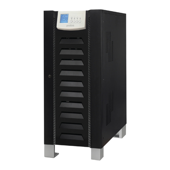
1. INTRODUCTION 1-1. Picture UPS This UPS series is a dual conversion system with sine wave output. Supply continuous, stable, and clean power for commercial and industrial needs. When utilities are lost, the UPS system will use batteries to produce uninterrupted output. The system implements an advanced digital controller to control the dual conversion system, and an isolated transformer at the output to protect the load and the UPS itself. - Page 4 Bypass input INV module REC module Line input Battery 1.3.2 Battery Mode When the utility fails, the UPS will transfer to battery mode without interruption. The UPS will convert electricity from the battery to output. At this time, the static bypass is still in standby. If the utility recovers, the UPS will transfer to line mode again.
- Page 5 1.3.4 ECO Mode ECO mode can be enabled or disabled by user settings. The default setting is disabled. If it is necessary to have high efficiency performance instead of high power quality, it is better to activate the "ECO" mode. In this mode, the load will be backed up through Bypass input when utility quality is OK.
- Page 6 INSPIRE 63360-EL INSPIRE 63380-EL INSPIRE 633100-E INSPIRE 633120-EL INSPIRE 633160-EL 1.4 Overview 1) Interface 4) Fan 2) Terminal 5) Communication 3) Breakers and switches 6) Cold start button. This button is located in the same location. same for all series.
-
Page 7: Important Safety Warnings
2. IMPORTANT SAFETY WARNINGS 2-1. Conventions and Use of Symbols Conventions used: COMMEMORATION! identify conditions that may result in personal injury; COMMEMORATION! identify conditions that may result in damage to other units or equipment Which is connected. Warning, risk of electric shock Warning, risk of danger Warning, risk of electric shock, energy storage time drained Refer to the operating instructions... -
Page 8: Safety Instructions
2-2. Safety Instructions COMMEMORATION! Before installing and using this equipment, please read all UPS instructions and warning signs in this manual. Keep this manual in a place that can be easily accessed. COMMEMORATION! This guide is only for qualified personnel. The tasks described in this guide can only be performed by expert technicians. - Page 9 COMMEMORATION! The battery circuit is not insulated; do not touch part of the battery. ATTENTION! When batteries are replaced, a set of batteries should be all replaced and do not use used batteries. ATTENTION! Do not expose the battery to fire or high temperatures. Because the battery can explode. ATTENTION! Batteries can pose serious risks to health and the environment.
-
Page 10: Installation
3. INSTALLATION 3-1. Basic Needs ➢ Environment Temperature: 0°C ~ +55°C ➢ Storage Temperature: -15ºC ~ 60ºC ➢ Humidity: 5% ~ 95% ➢ Altitude: If the UPS is installed below 1000m altitude, the UPS power will not decrease. When above 1000m, the output power will decrease following the following table. -
Page 11: Disassembling And Moving
3-2. Disassembling and Moving ➢ Check if there is any damage to the carton before opening. ➢ Then follow these steps to remove the UPS from the carton and pallet. Remove the carton and foam. Untie what appears in the image. Setting up two wires. -
Page 12: Electrical Connection
4. ELECTRICAL CONNECTION 4-1. Power Connection All connections can be accessed from the front panel of the UPS. It is enough to open the front door for cable connection. See the chart panel below for the entire series. INSPIRE 63360-EL INSPIRE 63380-EL INSPIRE 633100-EL INSPIRE 633120-EL... - Page 13 ➢ INSPIRE 633100-EL/INSPIRE 633160-EL The earthing terminal looks like this: The specifications of internal breakers, fuses and switches look like below: Breaker Insert Battery Exodus Fuses Model UPS LINE Enter BYPASS M-BYPASS Breaker Switch INSPIRE 63360-EL 125A/3P 125A/3P 125A/3P 315A 125A/3P INSPIRE 63380-EL 225A/3P...
- Page 14 Cable size recommendations are attached below: Line Insert and Earthing BYPASS/OUTPUT BATTERY Model UPS Size Diameter Diameter Diameter Size (AWG) Size (AWG) (mm2) (mm2) (mm2) (AWG) INSPIRE 63360-EL ≤ 1/0 ≥ 40 ≤ 1/0 ≥ 40 ≤ 3/0 ≥ 80 INSPIRE 63380-EL ≤...
-
Page 15: Communication
4-2. Communication UPS provides several variations of communication. The description is as follows: 4.2.1 Smart Slots Smart slots can provide SNMP solutions for remote monitors. Ask suppliers for more detailed information. 4.2.2 Dry Contact It has 5 outputs and 4 dry contact inserts. The detailed functions are attached below. The output of dry contact provides only passive states: closed and open. - Page 16 Details of the electrical parameters of the contact are attached below: Contact Parameters Recommendations Maximum 24VDC 230VAC Voltage (V) Exodus Current (mA) Voltage (V) Put into Current (mA) Application: Output dry contacts: Enter dry contacts: Explanation of the Function of the Contact output: Contact Output Function Description Default...
- Page 17 Battery External Temperature Constant Trip battery switch Constant BB TRIP 4.2.3 EPO Emergency Power Off (EPO) is the ability to shut down the system. It contains two terminal strip pins. When the circuit is open, it activates the system shutdown and disconnects the output. When the circuit is connected, the UPS resumes normal operation.
- Page 18 ➢ Single unit monitor app: First, use either the RS485 to RS 232 converter port or the RS485 port for Modbus/TCP converter as the converter medium between RS485 and the computer. Follow the chart below for a wired connection between RS485 and the media converter: Then, follow this diagram to connect to your PC: RS-485 to RS-232 converter RS-485 to Modbus/TCP converter...
-
Page 19: Implementation
5. IMPLEMENTATION 5-1. Getting Started Procedure Although this UPS supports battery startup function, we still recommend following the steps below to turn on the UPS. ➢ Before turning on the UPS, make sure the input and output cable connections are complete. Please follow the section 4.1 for wired connections. -
Page 20: Shutdown Procedure
5-2. Shutdown Procedure ➢ Press the to enter the main menu. ➢ Press the "Turn UPS ON/OFF" icon. "Turn UPS OFF" will appear and select the icon to turn off the UPS. ➢ Turn off the line breaker, insert and switch the battery. ➢... -
Page 21: Lcd Information
6-2. LCD Information 6.2.1 Basic Startup Screen Main Page After the UPS is turned on, the LCD will turn on first and then display the main page. ➢ Start When you first turn on the UPS, it takes a few seconds to turn on the LCD. Please wait. ➢... -
Page 22: Sub Menu
6-3. Sub menu 6.3.1 Sub-menu controls Press the icon to enter the control menu. Control Menu ➢ Turn UPS on/off If the UPS is already turned on, the screen will display "Turn UPS OFF". If the UPS is turned off, the screen will display "Turn UPS ON". ➢... - Page 23 Battery Test Confirmation Screen ➢ Clear inoperable status 6.3.2 Status sub-menu Press the icon to enter the Status page. It has 5 options: Input, Bypass, Output, BAT., Temp., and PAR. Items Description Input Displays real-time input line voltage, input phase voltage, and input frequency. Bypass Displays real-time line bypass voltage, bypass phase voltage, bypass frequency and bypass current.
- Page 24 l PUT INTO Enter Status l BYPASS Status Bypass l BAT. Battery Status...
- Page 25 l EXODUS Output Status l TEMP. l PAR. Voltage range for different modes...
- Page 26 6.3.3 Sub-menu settings This submenu is used to set UPS parameters. There are 3 options: UPS Settings, General settings and Advanced settings. Press the icon to enter the settings menu page. NOTE: Not all settings are available in every mode of operation. If the setting is not available in the current mode, the LCD will still display its original setting parameters without being able to change the parameters.
- Page 27 Battery Settings Battery settings screen 1 l Number of battery blocks: This is to set the number of batteries per string. The default setting is 32. l Battery capacity: This is to regulate the battery capacity. The default setting is 100Ah. l Maximum charger current: This is to regulate the maximum charger current.
- Page 28 Advanced Settings There are two permissions for Advanced Settings: User and Factory. Advanced Settings → Users It is required to enter a password to access the "Advanced settings" page. After entering the password, click the "OK" button to log in. Advanced Menu Settings l Electrical Settings Electrical Setting Screen 1...
- Page 29 Electrical Settings Screen 2 l Parallel Setup Parallel Screen Setup l Battery Testing Settings Battery Test Settings Screen 1 Battery Test Settings Screen 2...
- Page 30 l Dry Contact Settings Dry Contact Settings Screen l Initialization Initialization Screen Advanced Settings → Hidden Factory Factory settings are hidden to avoid operating errors. It is required to enter a password to access the "Advanced settings" page in advance. After entering the password, click the "OK" button to log in. Advance Setting Menu After accessing the Advanced settings menu, click the "Back arrow"...
- Page 31 Show Hidden Factory Settings Factory Menu Settings After clicking the "Factory settings" icon, it will display five options: Factory test mode, Factory settings, Voltage calibration, Current calibration, and Installation Information. l Factory Test Mode...
- Page 32 l Factory Settings: Will display the default settings from the factory. l Voltage calibration: It can calibrate the input voltage, inverter voltage, bypass voltage, output voltage, battery voltage and BUS voltage. l Calibrate current: It can calibrate output current, inverter current and output current.
- Page 33 l Installation Information: Set the system installation date, system maintenance date, battery installation date, and battery maintenance date. 6.3.4 Sub-menu services Press the icon to enter the Services page. There are six items to choose from: Alert information, Important event information, Event log, Settings log, Export data to USB, and About. Service Page Items Description...
- Page 34 l Warning Information Warning Information Screen l Key Event Information Key Event Information Screen l Event Logs Event Log Screen 1) This is to record all events on the UPS. Information including time, code, description, date and the time of the incident. If more than 5 events are listed on the screen, click the down arrow to see next page. 2) Check Chapter 8 for detailed warnings and error codes.
- Page 35 l About 1) UPS Serial Number 2) MCU Firmware Version 3) DSP Firmware Version 4) Show Firmware Version...
-
Page 36: Maintenance
7. MAINTENANCE Commemoration! Inside maintenance is only available to technicians with qualified electrical knowledge. There is still a possibility of high voltage inside the unit even after disconnecting all connections. 7-1. Maintenance ➢ Check that the touched LCD is working properly. ➢... -
Page 37: Problem Solving
8. PROBLEM SOLVING 8-1. Warning Code Code Status What to do? Battery open Check that the battery cable is connected properly and the battery switch is on. Line phase error Please check the phase order of the line enter. Bypass phase error Please check the bypass phase order Overcharging the Battery Check the battery voltage and then restart the unit. - Page 38 Overtemperature warning on Reduce connected loads or cool the ambient temperature. SCR Inverter. Overtemperature warning on Reduce connected loads or cool the ambient temperature. SCR bypass. Overtemperature warning on Reduce connected loads or cool the ambient temperature. the control board. Overtemperature warning on Reduce connected loads or cool the ambient temperature.
-
Page 39: Error Codes
8-2. Error Codes Code Status What to do? BUS start failed High BUS voltage Restart the unit. If the problem persists, please Low BUS voltage contact the service. INV soft start failed High INV voltage Low INV voltage L1 phase INV shorted L2 phase INV shorted Disconnect the load first. - Page 40 L3 INV SCR phase faulty Phase L1 bypass SCR is broken L2 phase faulty SCR bypass L3 phase bypass SCR is broken Parallel number settings are not compatible Check the parallel number settings on the parallel UPS. in parallel systems. Output frequency settings...
-
Page 41: Specifications
9. SPECIFICATIONS Table 1: Line inserts 160K Type 100K 120K Capacity 160K 10KVA 15KVA 20KVA 30KVA 40KVA 60KVA 80KVA 100KVA 120KVA 144KW 9KW 13.5KW 18KW 27KW 36KW 54KW 72KW 90KW 108KW Rated voltage 3 x 380/400V (3Ph + N) Rated Frequency 50Hz/60Hz Voltage range 165V... -
Page 42: Parallel Installation Guide
Table 4: Bypass Type 100K 120K 160K Rated voltage 3 x 380/400V (3Ph + N) Rated 50Hz/60Hz Frequency Voltage range 176V 264V (Ph-N) / 304V 456V (Ph-Ph) Frequency 46Hz 54Hz @50Hz; 56Hz 64Hz @60Hz range Transfer time Synchronization: 0ms Overload 110% 125%: 10min, 125% 150%: 60s, >150%: 200ms... -
Page 43: Parallel Overview Kit
UPS failure. During normal operation, the load is evenly divided across all UPS, which behaves as if they were a single UPS device. If one UPS fails or needs to be turned off to maintenance, then the system will continue to run without interruption. UPS modules must be the same size so that the anticipated total load can be carried by N units. - Page 44 10.2.2. Cable Connection Two UPSs in parallel: Battery Battery INPUT INPUT OUTPUT INPUT INPUT OUTPUT BAT+ BAT+ BAT- BAT- Communication Connection UPS 1 UPS 2...
- Page 45 Three UPSs in parallel: Battery Battery Battery INPUT INPUT OUTPUT INPUT INPUT OUTPUT INPUT INPUT OUTPUT BAT+ BAT+ BAT- BAT+ BAT- BAT- Communication Connection USB 1 USB 2 USB 3 Apply the same wired connection above to connect 4 UPS in parallel. Recommended battery disconnect specifications for each UPS: Type One unit...
-
Page 46: Lcd Settings And Displays
10-3. LCD settings and displays This single-function UPS is well installed from the factory. If the default setting is "Single", it can be changed to a "parallel" model by configuring the LCD setting. Click the "Settings" button and then the "Advanced settings"... -
Page 47: Specifications
10-4. Specifications Type 100K 120K 160K Power range 60KVA 80KVA 100KVA 120KVA 160KVA 54KW 72KW 90KW 108KW 144KW Maximum number of parallels Output Power for Parallel Systems 240K 320K 400K 480K 640K 216K 288K 360K 432K 576K No-load Current <5A Power Unbalanced <5% @ 100% Load Ratio... - Page 48 10.5.2. Error Codes Code Status What to do? 1. Update all UPS firmware to the same version. Faulty switch line 2. After updating, if the problem persists, Line parallel missing contact your local dealer. CAN com. Broken Line master missing Restart the UPS.
- Page 49 Note: Closed on Saturdays, Sundays and local/regional Public Holidays. Register online for your Product Warranty at www.prolink2u.com Prolink is a registered trademark of Fida International (S) Pte Ltd. Other brands and product names are trademarks or registered trademarks of their respective holders. Product images are purely for illustrative purposes and may defer from the actual product.
Need help?
Do you have a question about the Giant II Series and is the answer not in the manual?
Questions and answers
How to reset batry replace alarm
To reset the battery replacement alarm on the PROLiNK Giant II Series, restart the UPS.
This answer is automatically generated