PROLiNK MASTER II Series User Manual
Hide thumbs
Also See for MASTER II Series:
- User manual (48 pages) ,
- User manual (32 pages) ,
- User manual (40 pages)
Table of Contents
Advertisement
ONLINE UPS
User Manual
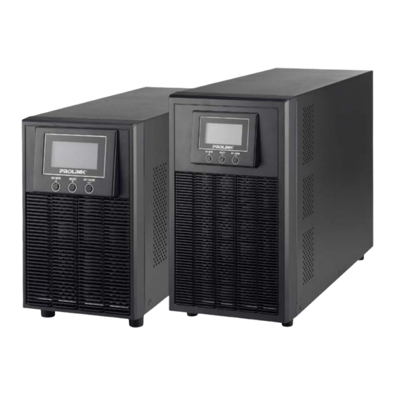
MASTER II SERIES (1P/1P) - TOWER
PRO800-ES/EL
1-3KVA
Version 1.00
(English)
BEFORE GETTING STARTED
This document is designed to aid you to get started with the device. If you experience problems following these
guides or need further information pertaining to the device, please visit our website at www.prolink2u.com. All
specifications are subject to the manufacturer's configuration at the time of shipping and may change without
prior notice, written or otherwise.
Advertisement
Table of Contents

Related Manuals for PROLiNK MASTER II Series


Summary of Contents for PROLiNK MASTER II Series
- Page 1 ONLINE UPS User Manual MASTER II SERIES (1P/1P) - TOWER PRO800-ES/EL 1-3KVA Version 1.00 (English) BEFORE GETTING STARTED This document is designed to aid you to get started with the device. If you experience problems following these guides or need further information pertaining to the device, please visit our website at www.prolink2u.com. All specifications are subject to the manufacturer’s configuration at the time of shipping and may change without...
-
Page 2: Table Of Contents
Table of Contents 1. Important Safety Warning ................... 1 1-1. Transportation ....................1 1-2. Preparation ......................1 1-3. Installation ......................1 1-4. Operation ......................1 1-5. Maintenance, service and faults ................1 2. Installation and setup ..................3 2-1. Rear panel view ....................3 2-2. -
Page 3: Important Safety Warning
1. Important Safety Warning Please comply with all warnings and operating instructions in this manual strictly. Save this manual properly and read carefully the following instructions before installing the unit. Do not operate this unit before reading through all safety information and operating instructions carefully. 1-1. - Page 4 verify that no current is present and no hazardous voltage exists in the terminals of high capability capacitor such as BUS-capacitors. Only persons are adequately familiar with batteries and with the required precautionary measures may replace batteries and supervise operations. Unauthorized persons must be kept well away from the batteries.
-
Page 5: Installation And Setup
2. Installation and setup NOTE: Before installation, please inspect the unit. Be sure that nothing inside the package is damaged. Please keep the original package in a safe place for future use. NOTE: There are two different types of online UPS: standard and long-run models. Please refer to the following model table. -
Page 6: Setup The Ups
4. Input circuit breaker 5. Network/Fax/Modem surge protection 6. Emergency power off function connector (EPO) 7. USB communication port 8. RS-232 communication port 9. SNMP intelligent slot 10. External battery connection (only available for L model) 11. Output terminal 12. Output circuit breaker 13. - Page 7 Please do NOT connect transformer to output of the UPS. Otherwise, it will cause UPS internal fault and force UPS to enter to fault mode. Please connect transformer to input of the UPS. 6. Connect to External Battery Pack When connecting external battery packs, please be sure to connect polarity correctly. Connect positive pole of battery pack to positive pole of external battery connector in UPS and negative pole of battery pack to negative pole of external battery connector in UPS.
- Page 8 Step 4: Communication connection Communication port: USB port R S-232 port I ntelligent slot To allow for unattended UPS shutdown/start-up and status monitoring, connect the communication cable one end to the USB/RS-232 port and the other to the communication port of your PC. With the monitoring software installed, you can schedule UPS shutdown/start-up and monitor UPS status through PC.
-
Page 9: Operations
3. Operations 3-1. Button operation Button Function Turn on the UPS: Press and hold ON/Mute button for at least 2 seconds to turn on the UPS. Mute the alarm: After the UPS is turned on in battery mode, press and hold this button for at least 3 seconds to disable or enable the alarm ON/Mute system. - Page 10 Function Display Backup time information Indicates the estimated backup time. H: hours, M: minute, S: second Configuration and fault information Indicates the configuration items, and the configuration items are listed in details in section 3-5. Indicates the warning and fault codes, and the codes are listed in details in section 3-7 and 3-8.
-
Page 11: Audible Alarm
3-3. Audible Alarm Battery Mode Sounding every 5 seconds Low Battery Sounding every 2 seconds Overload Sounding every second Fault Continuously sounding Bypass Mode Sounding every 10 seconds 3-4. LCD display wordings index Abbreviation Display content Meaning Enable Disable Escape High loss Low loss Battery... - Page 12 01: Output voltage setting Interface Setting Parameter 3: Output voltage For 200/208/220/230/240 VAC models, you may choose the following output voltage: 200: presents output voltage is 200Vac 208: presents output voltage is 208Vac 220: presents output voltage is 220Vac 230: presents output voltage is 230Vac (Default) 240: presents output voltage is 240Vac For 100/110/115/120/127 VAC models, you may choose the...
- Page 13 parameter 3 is from +7V to +24V of the nominal voltage. (Default: +12V) For 100/110/115/120/127 VAC models, the setting range in parameter 3 is from +3V to +12V of the nominal voltage. (Default: +6V) LLS: Low loss voltage in ECO mode in parameter 2. For 200/208/220/230/240 VAC models, the setting range in parameter 3 is from -7V to -24V of the nominal voltage.
- Page 14 65Hz(Default: 63.0Hz) LLS: Bypass low Frequency point For 50Hz output frequency models: 45-49Hz: setting the frequency low loss point from 45Hz to 49HZ(Default: 47.0Hz) For 60Hz output frequency models: 55-59Hz: setting the frequency low loss point from 55Hz to 59Hz(Default: 57.0Hz) 09: Programmable outlets enable/disable ...
-
Page 15: Operating Mode Description
14: Charger Boost voltage setting Interface Setting Parameter 3: Set up the charger boost voltage. 2.25-2.40: setting the charger boost voltage from 2.25 V/cell to 2.40V/cell. (Default: 2.36V/cell) 15: Charger Float voltage setting Interface Setting Parameter 3: Set up the charger float voltage. 2.20-2.33: setting the charger float voltage from 2.20 V/cell to 2.33V/cell. -
Page 16: Faults Reference Code
Standby mode UPS is powered off and no output supply power, but still can charge batteries. Fault mode When a fault has occurred, the ERROR icon and the fault code will be displayed. 3-7. Faults Reference Code Fault event Fault code Icon Fault event Fault code... -
Page 17: Troubleshooting
4. Troubleshooting If the UPS system does not operate correctly, please solve the problem by using the table below. Symptom Possible cause Remedy No indication and alarm even The AC input power is not Check if input power cord though the mains is normal. connected well. -
Page 18: Storage And Maintenance
Symptom Possible cause Remedy Fault code is shown as 14 and the The UPS shut down Check output wiring and if automatically because connected devices are in icon is lighting on LCD short circuit occurs on the short circuit status. display and alarm is continuously UPS output. -
Page 19: Specifications
6. Specifications PRO801-ES / PRO8015-ES / PRO802-ES / PRO803-ES / MODEL PRO801-EL PRO8015-EL PRO802-EL PRO803-EL CAPACITY* 1000VA/900W 1500VA/1350W 2000VA/1800W 3000VA / 2700W INPUT 160VAC/140VAC/120VAC/110VAC ± 5 % or 80VAC/70VAC/60VAC/55VAC ± 5 % Low Line Transfer ( based on load percentage 100% - 80 % / 80 % - 70 % / 70 - 60 % / 60 % - 0) Low Line Voltage 175VAC/155VAC/135VAC/125VAC ±... - Page 20 Register Online For Your Product Warranty @ www.prolink2u.com/register PROLiNK® is a trademark of FIDA INTERNATIONAL (S) PTE LTD and is manufactured under its authority. All other brands, products, services, logos and company names mentioned herein are trademarks of their respective owners.
Need help?
Do you have a question about the MASTER II Series and is the answer not in the manual?
Questions and answers