
Related Manuals for PROLiNK PRO2000LD


Summary of Contents for PROLiNK PRO2000LD
- Page 1 LINE INTERACTIVE UPS User Manual OUTDOOR LINE INTERACTIVE UPS (1P/1P) - RACK PRO2000LD 2KVA Version 1.00 (English)
-
Page 2: Table Of Contents
Table Of Contents ABOUT THIS MANUAL ..........................1 1.1. Purpose ..............................1 1.2. Scope ..............................1 SAFETY INSTRUCTIONS ........................... 1 INTRODUCTION ............................2 System Architecture ..........................2 UPS Module ............................3 PTS Module (Optional) ......................... 4 INSTALLATION ............................6 Unpacking and Inspection ........................6 Mounting the UPS .......................... -
Page 3: About This Manual
1. ABOUT THIS MANUAL 1.1. Purpose This manual contains important instruction that must be followed when install, service or maintain the product. Please read the instruction and drawings carefully before installations and operations. Keep this manual in a safe place for future reference. 1.2. -
Page 4: Introduction
3. INTRODUCTION The battery backup system provides constant and reliable backup power to outdoor equipment. It consists of Uninterruptible Power Supply (UPS) System and optional Power Transfer Switch (PTS) that provide backup power when the line is unqualified. These components should be mounted inside an enclosure to provide protection from most weather conditions. -
Page 5: Ups Module
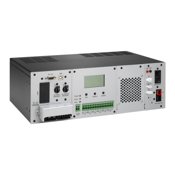
3.2 UPS Module The UPS module provides utility power to load when line is qualified. And an automatic voltage regulator (AVR) is embedded to provide stable power to the load. It will instantly switch to emergency backup power during utility power failure or interruption. The front panel view is shown as below. Figure 2: Front Panel of UPS AC Input Terminal Block This terminal block is the UPS AC line power input. -
Page 6: Pts Module (Optional)
External FAN Connector To provide DC Power (48Vdc, 3 Amp Max) to an optional 48Vdc fan. PTS Control Connector This connector provides power to control the PTS unit. Battery Breaker This over-current protection is used as an on/off switch for the battery power. It must be switched on for proper UPS operation. - Page 7 Switch UPS or bypass output can be selected by this switch. AC Output Breaker This circuit breaker marked with “OUTPUT’’ is a resettable protective thermal circuit breaker to protect the output from overloads and short circuits. AC Input Breaker This circuit breaker marked with “UPS INPUT’’ provides input power protection for the UPS. AC Output Receptacles These receptacles are ready to use for optional battery heating pads or a PC for maintenance.
-
Page 8: Installation
4. INSTALLATION 4.1 Unpacking and Inspection Before installation, please remove the unit from its box carefully since the UPS is heavy. Follow the below guidelines to unpack and inspect the unit. 1. Select a suitable area for unpacking and be sure that nothing inside is damaged. 2. -
Page 9: Wiring
Figure 5: PTS with Bracket for rack mounting 4.4 Wiring WARNING! All electrical wiring must be performed by a qualified electrician or trained personnel. Make sure the line power is off. Switch off all input and output circuit breakers on the UPS unit before making any electrical connections. 4.4.1 Wiring the UPS 1. - Page 10 4.4.3 Wiring External Batteries Unit supports 48Vdc battery. Connect all battery packs as below chart. It’s suggested to connect at least 100Ah capacity battery. Figure 7: Battery Connection Chart...
-
Page 11: Operation
5. OPERATION To power up the UPS, ensure the switch on PTS is in “UPS Mode” position. Before commissioning, make sure batteries are fully charged and line power is qualified. 5.1 Switch on UPS in Line mode Switch on battery circuit breaker. All LEDs will be on and LCD will display Startup page, and fan will be on. Switch on AC input breaker. -
Page 12: Operation The Control Panel
5.5 Operation the Control panel The control panel includes four-line LCD display, three indicators, three function keys, input contacts and six sets of dry contacts. It can be rotated 90 degree for vertical installation. Figure 8: Control Panel 5.5.1 LED Indicator LED Indicator Messages Solid On... - Page 13 5.5.3 LCD Menu Tree Users can check the status, view event log, set parameters and control of UPS via LCD panel. See below Menu Tree. Power on Startup …... After 6sec, enter default page automatically. yy-mm-dd hh:mm Mode: xxxxx Default page OP-V: xxx.xV Load : xxx% Enter...
- Page 14 Setting menu Control menu ► Dry Contact ▼ ► 1. Self Test ▼ 2. Dry Test Input Contact 3. Ext Fan Test AVR Feature Line Qualify 4. On/Off Ctrl Line Detect ▼ 5. Event/TM Reset Sense Type Bat Temp Comp ▲...
- Page 15 5.5.4 Default page After power on, Startup page will display. It will automatically switch to default page after 6 sec. Default page Explanation Date and time yy-mm-dd hh:mm UPS current operation mode Mode: xxxxx OP-V: xxx.xV UPS output voltage Load : xxx% UPS load percent Operation mode 5.5.5...
- Page 16 5.5.7 Status menu Status menu shows the basic measured information of UPS. Users can select displayed parameters by pressing ENTER key. Press ESC button in any page will return to default page. Menu item LCD display Explanation 1. Serial No. ▼...
- Page 17 5.5.9 Setting menu User can set various critical parameters in this menu. Choose the desired function on the screen by pressing ENTER button. Press ESC button to return to default page. Setting page Explanation Dry Contact: It indicates programmed values of C1-C6 contacts. ►...
- Page 18 Ext. Fan: It indicates ambient temperature setting to switch on the external fan. The default value is 25°C. Bat. Low Volt: It’s allowed to set the low battery warning voltage. The Bat Low Volt ▼ resettable range is 42.0~55.0V. The default value is 46V. Charger I Charger I: It’s to configure the charger current.
-
Page 19: Rs232/Usb Interface
RS232/USB interface Users can check UPS status, view event log, set parameters and control UPS via RS232/USB interface. 5.6.1 RS232/USB connection Connect the UPS and computer with standard RS232 or USB cable. 5.6.2 HyperTerminal Set Up With built-in communication tool HyperTerminal in Windows, device can communicate with computer. Follow below steps to step up HyperTerminal. - Page 20 Figure 14: Connect To Screen Step 4: It will pop up “COM Properties” screen and select port setting as shown in Figure 15 and click OK. Figure 15: COM Properties Step 5: A blank window with the entered file name will pop up. Refer to Figure16. In the File menu, select Properties and Click.
- Page 21 Figure 16: HyperTerminal Screen Step 6: The [Name of Unit] Properties screen will pop up as shown in Figure 17. Click on the Settings tab. Select all columns as below figure and click ASCII Setup button. Figure 17: ASCII Properties Screen Step 7: Set up all columns in the ASCII Setup screen as shown in Figure 18.
- Page 22 Figure 18: ASCII Setup Screen Step 8: Press Enter to go to UPS screen and access the UPS via RS232/USB communications.
- Page 23 5.6.3 RS232/USB Menu Tree The complete Menu Tree is shown below with all default values. UPS Model: Outdoor2000 ID 92611308100015 [0-MAIN MENU] 1 Unit Specification 2 Input / Output Values 3 Control 4 System Setting 5 Line Conditioning Setup 6 Programmable Contacts Setup 7 Event Log View 8 Login Administrator Date &...
- Page 24 5.6.4 RS232/USB Main Menu The RS232 / USB menus are hierarchical. Press ENTER to access main menu as shown in Figure 20. Type in the number of submenu and press Enter button to access a particular submenu. Press Enter to refresh the screen, the Status, Faults, and Alarms readouts.
- Page 25 Displayed contents of Line Status, Output Status, Faults and Alarms are listed in Figure 21. Line Status: [Current Status] Output Status: [Current Status] Contact Status: [Current Status] Ext. Fan Status: [Current Status] Faults: [If any, otherwise blank] Alarms: [If any, otherwise blank] >_ ▼...
- Page 26 5.6.5 Unit Specifications To access Unit Specification menu, type 1 and press Enter on the main menu. To return to the main menu, press Esc and then press Enter buttons. It lists unit specifications as following table. [ 1 - Unit Specifications ] Unit Model The model name Unit Freq...
- Page 27 5.6.7 Control To access Control menu, type 3 and press Enter on the main menu. To return to the main menu, press Esc and then press Enter button. Following table lists all control options. [ 3 - Control ] 30 Self Test Start or stop for the self test.
- Page 28 5.6.9 Line Conditioning Setup This option allows user to change various detection and warning levels for input AC voltages, qualified and unqualified values, transfer & re-transfer setting points for going in & out Battery mode, Boost or Buck modes. See detailed descriptions in the following Parameter Description table. Electrical equipment is designed to operate at maximum efficiency under specific standard supply voltage.
- Page 29 Parameter Descriptions Table (All levels are user-programmable. Some values are interdependent. AVR Function Disable AVR Function Enable Default Setting Selections or Default Setting Selections or Selectable Selectable Range Range 50. Buck Function √ 51. Boost Function √ 52. Sense Type Normal Normal Normal...
-
Page 30: Optional Snmp Card
5.6.10 Event Log View Menu 7 lists the Event log status. To access Event Log menu, type 7 and press Enter on the main menu. To return to the main menu, press Esc and then press Enter buttons. [ 7 – Event Log View ] 70. -
Page 31: Specifications
6. SPECIFICATIONS 6.1 Line Mode Specifications Rated Power 2000VA/1600W Power factor Nominal battery voltage 48Vdc Utility Voltage Waveform Sinusoidal (utility or generator) Utility qualify time setting 3/10/30 seconds adjustable, Nominal Input Voltage 120Vac or 230/240Vac AVR function Enable/ Disable Utility voltage range 88 ~152 Vac or 176 ~ 300Vac user programmable. -
Page 32: Battery Mode Specifications
6.2 Battery Mode Specifications Output Waveform Pure sine wave Output Voltage Regulation 120 or 230/240Vac± 5% Output Frequency 50/60Hz ± 0.1% Nominal DC Voltage 48Vdc DC voltage range 42.5 ~ 60Vdc(48V) Low DC warning voltage 42 ~ 55Vdc adjustable Peak Efficiency >90% No Load Power Consumption 28W @48Vdc... -
Page 33: Charger Mode Specifications
6.3 Charger Mode Specifications Appropriate battery type Charging Current 2Amp/ 4Amp/ 6Amp/ 8Amp/10Amp adjustable Charger Current(A) Max charger current limitation Temperature °C Charging Algorithm 3-Step Boost CC, CV Float Battery Type 24/48Vdc 24/48Vdc Charger voltage Setting @25 °C 28.2/56.4Vdc 27.0/ 54.0Vdc Charging voltage is compensated according to battery temperature -2.5mV /-3.0mV/ -3.5mV/ -4.0mV per cell per°C compensated coefficient Battery Temperature Control... -
Page 34: Trouble Shooting
7. TROUBLE SHOOTING 7.1 For PTS Module Problem Possible Cause Remedy No output available from AC circuit breaker may be Close the external AC input breaker. External PTS. OPEN. Line AC power is not available. Check if utility is available with the AC voltmeter and contact Utility Company. -
Page 35: For Ups Module
7.2 For UPS Module Problem Possible Cause Remedy No output. AC input and output circuit breakers Turn on input and output circuit breakers. are off. No line power input. Turn on AC input breaker. Red LED is lit solid on front panel Read fault event under Event Log in LCD indicating fault. -
Page 36: Appendix: Approximate Back-Up Time Table
8. Appendix: Approximate Back-up Time Table Model Load (VA) Backup Time @ 48Vdc 100Ah (min) Backup Time @ 48Vdc 200Ah (min) 1581 3161 1581 1054 1000 2KVA 1200 1400 1600 1800 2000... - Page 37 Register Online For Your Product Warranty @ www.prolink2u.com/register PROLiNK® is a trademark of FIDA INTERNATIONAL (S) PTE LTD and is manufactured under its authority. All other brands, products, services, logos and company names mentioned herein are trademarks of their respective owners.
Need help?
Do you have a question about the PRO2000LD and is the answer not in the manual?
Questions and answers