Advertisement
Quick Links
RM3545A-1
RM3545A-2
RESISTANCE METER
Read carefully before use.
Keep for future reference.
When using the instrument for the
first time
Oct. 2023 Edition 1
RM3545E965-00
Troubleshooting
p.4
p.7
p.8
HIOKI RM3545E965-00
Startup Guide
p.10
p.20
EN
[600656050]
Advertisement

Related Manuals for Hioki RM3545A-1


Summary of Contents for Hioki RM3545A-1
-
Page 1: Table Of Contents
RM3545A-1 RM3545A-2 Startup Guide RESISTANCE METER Read carefully before use. Keep for future reference. When using the instrument for the Troubleshooting first time Safety Information Maintenance and Service p.10 Part Names and Functions Error displays p.20 ... - Page 2 HIOKI RM3545E965-00...
- Page 3 Introduction When you receive the instrument, please inspect it for any Thank you for choosing the Hioki RM3545A-1, RM3545A-2 damage or other issues prior to use. If you find any damage Resistance Meter. To ensure your ability to get the most out...
-
Page 4: Safety Information
Standard IEC 61010 and has been thoroughly tested for safety prior to shipment. However, using the instrument in a way not described in this manual may negate the provided safety features. Before using the instrument, be sure to carefully read the following safety precautions. HIOKI RM3545E965-00... - Page 5 Use of the instrument while it is malfunctioning could result in serious bodily injury. If you find any damage, Doing so could cause a short-circuit, resulting in contact your authorized Hioki distributor or reseller. serious bodily injury. WARNING Before measuring When using the instrument while connected „...
- Page 6 Fixing with other screws could cause damage to the and contacting another conductive object could cause instrument, resulting in bodily injury. If you lose or an electric shock. damage the screws, contact your authorized Hioki Follow the steps below before wiring the „ distributor or reseller.
-
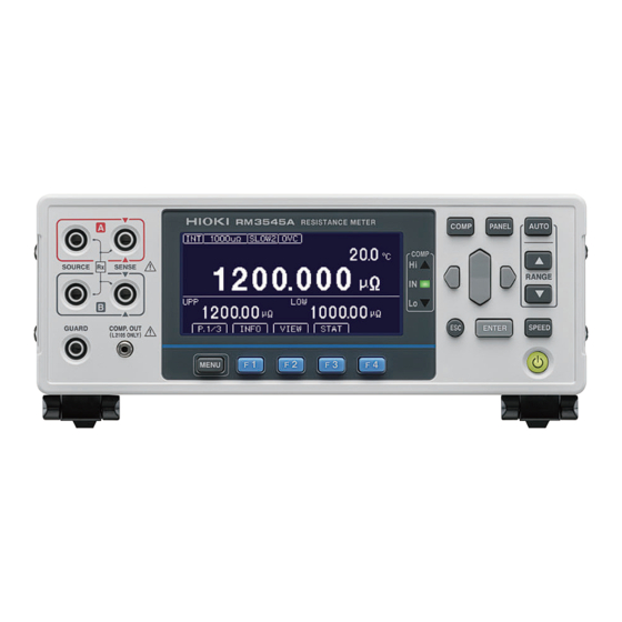
Page 7: Part Names And Functions
Switches On/Off the main power screen. supply of the instrument. MENU Displays the Settings screen or Multiplexer unit slot Install the Z3003 Multiplexer Unit. switches the pages. (Max. 2) (RM3545A-2 only) COMP.OUT terminal Connect the L2105 LED Comparator Attachment. *1. Programmable controller HIOKI RM3545E965-00... -
Page 8: Measurement Process
Weld resistance, Signal contacts, Power contacts, × × × Dimensions Approx. 215W 306.5D mm (8.46W Temperature-rise test, etc. × 3.15H 12.07D in.) (except protruding parts) Weight Approx. 2.7 kg (6.0 lbs) (RM3545A-1) Approx. 3.4 kg (7.5 lbs) (RM3545A-2) HIOKI RM3545E965-00... - Page 9 0.5 V or less (load current: See: Instruction Manual "4.5 Correcting for the Effects 10 mA) of Temperature (Temperature Correction [TC])" Maximum 50 mA/channel output current (14) Offset voltage compensation See: Instruction Manual "4.8 Compensating for Thermal EMF Offset (OVC Function)" HIOKI RM3545E965-00...
-
Page 10: Maintenance And Service
Maintenance and Service Repair and Inspection WARNING Do not attempt to modify, disassemble, or try „ to repair the instrument. Doing so could cause serious bodily injury or fire. Replace the fuse with a rated fuse. Reset the fuse holder. HIOKI RM3545E965-00... - Page 11 Troubleshooting If damage is suspected, read the “Before Returning for Repair” section to remedy the problem. If this does not help you, contacting your authorized Hioki distributor or reseller. Before Returning for Repair General issues Issue Items to check Possible causes...
- Page 12 Scaling The offset setting is Turn scaling off, or function incorrect. reconfigure the setting properly. Measurement leads The measurement Check the connections. leads are not connected properly. See "Measured values are unstable." (p. 1 2). HIOKI RM3545E965-00...
- Page 13 Insert the unit properly. Do been inserted. not allocate units that have not been inserted to channels. Nothing is shown. Auto-ranging is not See "Auto-ranging is not selecting a range. selecting a range. (The range is not appropriate.)" (p. 1 4) HIOKI RM3545E965-00...
- Page 14 The settings have been Check the settings. improperly configured. A temperature sensor 9451 Temperature Probe is other than that not supported. specified is used. HIOKI RM3545E965-00...
- Page 15 The channels cannot be The channel numbers have not The scan settings Configure the scan settings correctly. switched with the LOAD been set. have been improperly signal. The channels have been disabled. configured. The scan function has been turned off. HIOKI RM3545E965-00...
- Page 16 Control the BCD_LOW signal (failure to do so will cause the is not being output. controlled. RANGE_OUT signal not to be output). The multiplexer The MUX signal is not on. Turn on the MUX signal. channels cannot be switched with the LOAD signal. HIOKI RM3545E965-00...
- Page 17 Measurement leads are connected Do not connect measurement leads to the measurement multiplexer channel. to the measurement terminals on terminals on the front of the instrument Unable to load the front of the instrument. when using the multiplexer. multiplexer. HIOKI RM3545E965-00...
- Page 18 Perform zero adjustment. − Measurement leads Do not connect measurement leads to the are connected to the measurement terminals on the front of the measurement terminals on instrument when using the multiplexer. the front of the instrument. HIOKI RM3545E965-00...
- Page 19 Ω • When using the multiplexer in 2-wire mode, the contact check function is disabled. In addition, the ranges of 1000 m and less will not be available for use. HIOKI RM3545E965-00...
-
Page 20: Error Displays
Error displays When an error is displayed on the LCD screen, repair is necessary. Contact your authorized Hioki distributor or reseller. Display Description Remedy +OvrRng/-OvrRng Over-range Select the appropriate range. CONTACT TERM.A Measurement terminal A-side wiring Check for cable breakage and worn out... - Page 21 Disconnect the measurement leads and check whether or not the error occurs. If the error still occurs, request repair of the instrument. Furthermore, be sure to use a Hioki-specified fuse for replacement. Specified fuse: F1.6AH/250 V (non arcing) ×...
- Page 22 Enter password for Adjustment Mode. Enter the password for adjustment mode. INFO:041 Password is wrong. The adjustment mode password is incorrect. Please enter the correct password. INFO:080 Self-calibration is set to ″manual″. Self-calibration measurement is set to MANU. HIOKI RM3545E965-00...
- Page 23 HIOKI RM3545E965-00...
- Page 24 HIOKI RM3545E965-00...
Need help?
Do you have a question about the RM3545A-1 and is the answer not in the manual?
Questions and answers