
Related Manuals for Hioki RM3548


Summary of Contents for Hioki RM3548
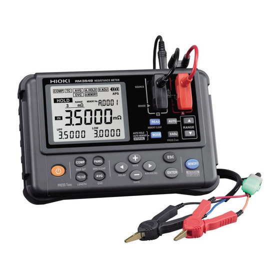
- Page 1 RM3548 Instruction Manual RESISTANCE METER May 2015 Revised edition 1 RM3548A981-01 15-05H...
- Page 3 How to use the Instruction Manual (this manual) See below, as appropriate: Be sure to always read the “Safety Notes” (p. 4) following sections. “Usage Notes” (p. 7) When you wish to use the “Overview” (p. 15) instrument immediately When you need further information ...
-
Page 5: Table Of Contents
Contents Introduction ..................1 Verifying Package Contents .............2 Safety Notes ..................4 Usage Notes ..................7 Overview Overview and Features ..........15 Component Names and Operation Overview .....16 „ Power-on settings ..............20 Flow of Measurement ...........21 Screen Layout ...............22 Checking the Measurement Target ......25 Preparing for Measurement Attaching the Strap ............28 Loading or Replacing the Batteries ......29... - Page 6 Contents Customizing Measurement Conditions Using Zero Adjustment..........44 Stabilizing Measured Values (Averaging Function) ...49 Compensating for Thermal Effects (Temperature Correction (TC)) ........50 Compensating for Thermal EMF Offset (Offset Voltage Compensation Function: OVC Function) ..51 Setting the Delay Time for Measurement (Delay Function) ................53 Switching the Measurement Current Ω...
- Page 7 Contents Memory Function (Saving and Exporting Measurement Data to a PC) Saving Data at Specified Time (Manual Memory) ..77 Saving Data Automatically When Measured Values Stabilize (Auto-Memory) ........78 Saving Data at Fixed Intervals (Interval Memory Function) ..........79 Displaying Saved Measurement Data (Memory Display Function) ..........81 Clearing Measurement Data (Memory Clear) .....82 Exporting Saved Measurement Data to a PC...
- Page 8 Contents Maintenance and Service 10.1 Troubleshooting ............108 „ Q&A (frequently asked questions and answers) ....108 „ Error display and actions............114 10.2 Repair and Inspection ..........115 10.3 Replacing Fuses ............116 10.4 Disposing of the Instrument ........117 Appendix Appx.1 Appx.
-
Page 9: Introduction
Introduction Introduction Thank you for purchasing the HIOKI RM3548 Resistance Meter. To obtain maximum performance from the product, please read this manual first, and keep it handy for future reference. Registered trademarks Windows and Excel are registered trademarks of Microsoft Corporation in the United... -
Page 10: Verifying Package Contents
In particular, check the accessories, panel switches, and connectors. If damage is evident, or if it fails to operate according to the specifications, contact your authorized Hioki distributor or reseller. • When transporting the instrument, use the same packaging materials used for the delivery to you. - Page 11 Verifying Package Contents Options For details, contact your authorized Hioki distributor or reseller. (p. Appx.28) L2107 Clip Type Lead 9467 Large Clip Type Lead 9453 Four-Terminal Lead 9772 Pin Type Lead 9465-10 Pin Type Lead 9454 Zero Adjustment Board Z2002 Temperature Sensor...
-
Page 12: Safety Notes
Safety Notes Safety Notes The instrument is designed to conform to IEC 61010 Safety Standards, and has been thoroughly tested for safety prior to shipment. However, using the instrument in a way not described in this manual may negate the provided safety features. Before using the instrument, be certain to carefully read the following safety notes. - Page 13 Safety Notes Notation In this manual, the risk seriousness and the hazard levels are classified as follows. Indicates an imminently hazardous situation that will result in death or DANGER serious injury to the operator. Indicates a potentially hazardous situation that may result in death or WARNING serious injury to the operator.
- Page 14 Safety Notes Symbols affixed to the instrument Indicates cautions and hazards. When the symbol is printed on the instrument, refer to a corresponding topic in the Instruction Manual. Indicates a fuse. Indicates DC (Direct Current). Symbols for various standards Indicates the Waste Electrical and Electronic Equipment Directive (WEEE Directive) in EU member states.
-
Page 15: Usage Notes
Before using the instrument the first time, verify that it operates normally to ensure that no damage occurred during storage or shipping. If you find any damage, contact your authorized Hioki distributor or reseller. DANGER Before using the instrument, check that the coating of the test leads or cables are neither ripped nor torn and that no metal parts are exposed. -
Page 16: Handling Precautions
TEMP.SENSOR, or COMP.OUT terminals. Precautions during shipment Observe the following during shipment. Hioki cannot be responsible for damage that occurs during shipment. CAUTION • During shipment of the instrument, handle it carefully so that it is not damaged due to a vibration or shock. - Page 17 Usage Notes Handling leads and cables DANGER To avoid electrical shock accident, do not short test leads where voltage is applied. CAUTION • Avoid stepping on or pinching the leads, which could damage the lead insulation. • To avoid damaging the cables, do not bend or pull the base of cables and the leads.
- Page 18 Usage Notes Batteries WARNING • Do not short circuit, charge, disassemble, or incinerate batteries. Doing so may cause an explosion and is dangerous. • To avoid electric shock accident, remove any test leads before replacing batteries. • After the replacement, be sure to reattach the cover. CAUTION Poor performance or damage from battery leakage could result.
- Page 19 Usage Notes Before connecting test leads DANGER To avoid electric shock or short-circuit accident, turn any measurement target off before connecting test leads. Before connecting the L2105 LED Comparator Attachment CAUTION • To prevent the instrument and the L2105 LED Comparator Attachment from breaking down, turn the power off before connecting the L2105 LED Comparator Attachment.
- Page 20 1 A flows. The instrument may be damaged. • Do not attempt to measure the internal resistance of a battery. The instrument will be damaged. To measure internal resistance of a battery, use a HIOKI 3554, 3555, BT3562, BT3563, or 3561 Battery HiTESTER.
- Page 21 Usage Notes IMPORTANT • The SOURCE terminals are protected with a fuse. If the fuse is broken, “FUSE” appears, and resistance cannot be measured. In such a case, replace the fuse. (p. 116) • Since the instrument uses DC current for measurement, it may be affected by thermal EMF (thermoelectromotive force), resulting in a measurement error.
- Page 22 Usage Notes...
-
Page 23: Overview
Overview 1.1 Overview and Features The Hioki RM3548 employs the four-terminal method to highly accurately measure the DC resistance of measurement targets including motor and transformer windings, and welding, PC board patterns, fuses, resistors, and materials such as conductive rubber. The instrument allows temperature correction and so is especially suitable for measurement targets whose resistance values change with temperature. -
Page 24: Component Names And Operation Overview
Component Names and Operation Overview 1.2 Component Names and Operation Overview Front Strap attachment Measurement holes (four) (p. 28) Display (p. 22) terminals (p. 30) Operation keys (p. 18) [POWER] Turns the power on/off. (p. 32) - Page 25 Component Names and Operation Overview Top view COMP. OUT terminal Connect an optional L2105 LED Comparator Attachment. (p. 66) USB terminal Connect a USB cable. (p. 86) TEMP.SENSOR terminal Connect the included Z2002 Temperature Sensor. (p. 31) Back view Fuse cover Contains a fuse for measurement circuit protection.
- Page 26 Component Names and Operation Overview Operation keys Description [COMP] key (p. 62) • Comparator: oFF → ON (ABS mode) → ON (REF% mode) [BEEPSET] key (press and hold) (p. 65) • Judgment sound: oFF → Hi → in → Lo → Hi-Lo → ALL1 → ALL2 [TC/∆T] key (p.
- Page 27 Component Names and Operation Overview Description [MEMORY] key (p. 77) • Saves the measured values (manual memory) [START/STOP] key (press and hold) (p. 79) • Starts/stops interval measurement (when in interval mode) [READ] key (p. 81) • Displays saved measurement data [MEMORY CLEAR] key (press and hold) (p.
-
Page 28: X84; Power-On Settings
Component Names and Operation Overview Power-on settings To perform one of the following settings, it is necessary to turn the power from off to on while holding-down a particular key. For details, see the indicated page. Clearing zero adjustment (p. 48) Switching to a different measurement current (p. -
Page 29: Flow Of Measurement
Flow of Measurement 1.3 Flow of Measurement Before using the instrument, be sure to see “Usage Notes” (p. 7). Preparing for measurement Measurement Attach the strap. (p. 28) Turn the power on and configure settings.* (p. 32) Load or replace the batteries. (p. 29) Connect the test leads to the measurement target. -
Page 30: Screen Layout
Screen Layout 1.4 Screen Layout Display (when the entire display is lit) Displays measurement conditions, settings, measured values, memory numbers (MEMORY No.), panel numbers, comparator settings, judgment results, etc. For information on the error display, see “Error display and actions” (p. 114). Remaining battery indicator (p. - Page 31 Screen Layout Length conversion measurement screen (p. 69) Temperature conversion (∆T) measurement screen (p. 67) Interval measurement screen (p. 79) Memory No. Elapsed time (The screen shows when ∆T is ON.) Non-measured value display (see “Verifying measurement errors” (p. 40) for details) Out-of-range Current fault...
- Page 32 Screen Layout Indicator Description Lit: The comparator function is enabled. Blinking: The processing of the key pressed cannot be performed (p. 62) because the comparator function is enabled. Lit: The length conversion function is enabled. Blinking: The processing of the key pressed cannot be performed (p.
-
Page 33: Checking The Measurement Target
Checking the Measurement Target 1.5 Checking the Measurement Target To carry out proper resistance measurement, change the measurement conditions appropriately according to the measurement target. Before starting measurement, use the examples recommended in the following table to configure the instrument. Recommended settings (Bold indicates a change from the factory default.) Temperature... - Page 34 Checking the Measurement Target *1 When the measurement target significantly depends on temperature, use the temperature correction function. *2 The interval measurement function allows you to save a measured value every fixed interval. (p. 79) IMPORTANT If a measurement fails with the PrSEt (preset) delay setting, set a long enough delay time.
-
Page 35: Preparing For Measurement
Preparing for Measurement Before using the instrument, be sure to see “Usage Notes” (p. 7). Attaching the strap (p. 28) Loading or replacing the batteries (p. 29) Connecting the test leads (p. 30) Connecting a Z2002 Temperature Sensor (p. 31) Inspecting the instrument (p. -
Page 36: Attaching The Strap
Attaching the Strap 2.1 Attaching the Strap Attaching the strap to the instrument allows you to use it with the strap around your neck. Follow the procedure below to attach the strap. Attaching the strap... -
Page 37: Loading Or Replacing The Batteries
Loading or Replacing the Batteries 2.2 Loading or Replacing the Batteries Before using the instrument for the first time, load the eight alkaline batteries (LR6). Before measurement, check that the instrument has sufficient remaining battery power. If the remaining battery level is low, replace the batteries. See the battery indicator to check the remaining battery level. -
Page 38: Connecting The Test Leads
Connecting the Test Leads 2.3 Connecting the Test Leads Use the included L2107 Clip Type Leads or select from our wide range of optional test leads. For more information on the lead options, see “Options” (p. 3). Test leads (Example: L2107 Clip Type Leads) The V mark indicates a SENSE lead. -
Page 39: Connecting The Z2002 Temperature Sensor (When Using Tc Or Δ T)
Connecting the Z2002 Temperature Sensor (When Using TC or ΔT) 2.4 Connecting the Z2002 Temperature Sensor (When Using TC or Δ T) Connect the Z2002 Temperature Sensor to the TEMP.SENSOR terminal. Connection method TEMP.SENSOR terminal Fully insert the jack. -
Page 40: Turning The Power On/Off
Turning the Power On/Off 2.5 Turning the Power On/Off Turning the power on Press the [POWER] key to turn the power on. Hold the key down until the entire display turns on. Entire display lit A self-test is started. The model name and version number are displayed during [POWER] the self-test. -
Page 41: X84; Automatic Power Off With Auto Power Save (Aps)
Turning the Power On/Off Automatic power off with auto power save (APS) When the instrument is not being used, the APS function automatically turns it off to reduce battery consumption. APS function ON Blinking Then, when a specific time elapses after the start of blinking, the instrument If no key is operated for 10 minutes automatically turns off. -
Page 42: Pre-Measurement Inspection
2.6 Pre-measurement Inspection Before using the instrument, inspect it to verify that no damage has occurred during storage or transportation and it operates normally. If you find any damage, contact your authorized Hioki distributor or reseller. Instrument and peripheral checking Inspection item... -
Page 43: Basic Measurement
Basic Measurement Before measurement, be sure to see “Measurement precautions” (p. 12). This chapter describes the basic operations for using the instrument. • “3.1 Setting the Measurement Range” (p. 36) • “3.2 Connecting the Test Leads to the Measurement Target” (p. 38) •... -
Page 44: Setting The Measurement Range
Setting the Measurement Range 3.1 Setting the Measurement Range Select a measurement range. Automatic range selection (the auto range) is also available. IMPORTANT When the auto range is used or the measurement range is set to 30mΩ or less, a maximum current of 1 A may constantly flow through the measurement target, and a maximum power of approximately 2 W may be applied*. - Page 45 Setting the Measurement Range Using the auto range Use the [AUTO] key to switch to the auto range. (The default setting is AUTO.) When the instrument is in the auto range mode, AUTO is lit. (The auto range) AUTO lit [AUTO] Toggles the auto range ON and OFF.
-
Page 46: Connecting The Test Leads To The Measurement Target
Connecting the Test Leads to the Measurement Target 3.2 Connecting the Test Leads to the Measurement Target Example: Using the L2107 Example: Using the 9772 (Press) Example: Using the 9453 The SENSE terminals should be located inside the SOURCE terminals. SOURCE A SOURCE B SENSE A... -
Page 47: Reading The Measured Value
Reading the Measured Value 3.3 Reading the Measured Value The instrument displays a resistance value. If a non-resistance value is displayed, see “Verifying measurement errors” (p. 40). To convert the measured resistance value, see the following pages: • “5.2 Performing Temperature Rise Test (Temperature Conversion Function (∆T))” (p. -
Page 48: X84; Verifying Measurement Errors
Reading the Measured Value Verifying measurement errors If a measurement is not performed correctly, the measurement error is displayed on the screen. Out-of-range* Indicates that the measurement or display range has been exceeded. If oF is displayed, the comparator judgment is “Hi”, and if -oF is displayed, the comparator judgment is “Lo”. - Page 49 Reading the Measured Value Temperature calculation error The Z2002 Temperature Sensor is not connected even when TC or ∆T is ON, or oF is displayed for the temperature. Check the connection of the Z2002 Temperature Sensor. IMPORTANT If the measurement target is connected to the SOURCE terminal, but a SENSE terminal has a bad contact, the displayed measured value may be unstable.
-
Page 50: X84; Holding A Measured Value
Reading the Measured Value Holding a measured value The auto-hold function helps to verify a measured value. When the measured value becomes stable, the value is automatically held. oFF → Auto-hold (A.HOLD) → Auto-memory (A.HOLD, A.MEMORY) → Interval (INTERVAL) → oFF Cancel Apply [MODE]... -
Page 51: Customizing Measurement Conditions
Customizing Measurement Conditions Before measurement, be sure to see “Measurement precautions” (p. 12). This chapter describes the functions useful to perform more sophisticated and accurate measurement. • “4.1 Using Zero Adjustment” (p. 44) • “4.2 Stabilizing Measured Values (Averaging Function)” (p. 49) •... -
Page 52: Using Zero Adjustment
Using Zero Adjustment 4.1 Using Zero Adjustment In the following cases, perform zero adjustment: (A resistance of up to ±3%f.s. can be canceled for any range.) • The measurement value is not cleared due to thermal EMF or other factors. →... - Page 53 Using Zero Adjustment Performing zero adjustment Short the test leads. L2107 Correct Incorrect Align the V symbols on the clips. SENSE SENSE SENSE SOURCE SOURCE SOURCE SOURCE SENSE Black Black SENSE-A SENSE-B SOURCE-A SOURCE-B Connect Connect 9453 (Option) Perform zero adjustment while the alligator clips are located outside and the lead bar is located inside.
- Page 54 Using Zero Adjustment Confirm that the measured value is within ±3%f.s. If no measured value is displayed, make sure that the test leads are connected correctly. If the connection is correct If the connection is wrong Press and hold the [0 ADJ] key to perform zero adjustment.
- Page 55 Using Zero Adjustment After zero adjustment Zero adjustment has succeeded Zero adjustment has failed [FAIL] The buzzer sounds and the The buzzer sounds and appears. measurement screen appears. Then, the measurement screen appears. Indicator ON Indicator OFF Zero adjustment failed When zero adjustment cannot be performed, the measured value before zero adjustment already exceeds ±3% of the full scale of each range or the instrument is in a measurement error state.
- Page 56 Using Zero Adjustment Clearing zero adjustment [0 ADJ] [POWER] When the power is off, while holding the key, press the key to clear the zero adjustment for all ranges. Turn the power off (if it is on). [POWER] [0 ADJ]...
-
Page 57: Stabilizing Measured Values (Averaging Function)
Stabilizing Measured Values (Averaging Function) 4.2 Stabilizing Measured Values (Averaging Function) This function averages the measurement values in order to display a single value. It helps to stabilize fluctuations in the measured values. oFF (factory default) → 2 → 5 → 10 → 20 Changes the Cancel averaging frequency. -
Page 58: Compensating For Thermal Effects (Temperature Correction (Tc))
Compensating for Thermal Effects (Temperature Correction (TC)) 4.3 Compensating for Thermal Effects (Temperature Correction (TC)) This function converts a measured resistance value, based on the reference temperature, to display the converted value. For the principles of temperature correction, see “Appx. 4 Temperature Correction Function (TC)” (p. Appx.4). To perform temperature correction, connect the Z2002 Temperature Sensor to the TEMP.SENSOR terminal on the side of the instrument. -
Page 59: Compensating For Thermal Emf Offset (Offset Voltage Compensation Function: Ovc Function)
Compensating for Thermal EMF Offset (Offset Voltage Compensation Function: OVC Function) 4.4 Compensating for Thermal EMF Offset (Offset Voltage Compensation Function: OVC Function) This function automatically compensates for an offset voltage caused by thermal EMF or an internal offset voltage. (OVC: Offset Voltage Compensation) See: “Appx. - Page 60 Compensating for Thermal EMF Offset (Offset Voltage Compensation Function: OVC Function) IMPORTANT • When the offset voltage compensation function is ON (the OVC indicator is lit), the measured value will be slow to refresh. Ω • The OVC function cannot be used in the 3k range or higher.
-
Page 61: Setting The Delay Time For Measurement (Delay Function)
Setting the Delay Time for Measurement (Delay Function) 4.5 Setting the Delay Time for Measurement (Delay Function) This function adjusts the time for measurement to stabilize by inserting a waiting period after use of the OVC or the auto range function to change the measurement current. - Page 62 Setting the Delay Time for Measurement (Delay Function) PrSEt (preset) → 10 ms → 30 ms → 50 ms → 100 ms → 300 ms → 500 ms → 1000 ms Press the [] (DELAY) key to display a selection screen. Press and hold Cancel Apply...
-
Page 63: Switching The Measurement Current (In The 300M Ω Range)
Switching the Measurement Current (In the 300mΩ Range) 4.6 Switching the Measurement Current (In the Ω 300m Range) Ω With this instrument, the measurement current for the 300m range can be changed to 300 mA (100 mA at the time of shipment from the factory). This makes it possible to measure large current wiring under conditions that are similar to the actual usage conditions. - Page 64 Switching the Measurement Current (In the 300mΩ Range) Turn the power off (if it is on). Make sure that the power is off, and holding down the , press the key. When Lo is selected (100 mA) Not lit [] [POWER] Cancel and move to the Use the...
- Page 65 Switching the Measurement Current (In the 300mΩ Range) When measuring resistance for connection sections (e.g., connector contact, welded section, caulked section, screw-secured section) through which large current flows, such as power supply cables and ground cables, it is desirable that measurement be performed using the maximum current, as far as possible, that can actually flow through those sections.
- Page 66 Switching the Measurement Current (In the 300mΩ Range)
-
Page 67: Judgment And Conversion Functions
Judgment and Conversion Functions This chapter describes the measured value judgment and conversion functions. “5.1 Judging Measured Values (Comparator Function)” (p. 60) “5.2 Performing Temperature Rise Test (Temperature Conversion Function (∆T))” (p. 67) “5.3 Measuring the Length of a Conductor (Length Conversion Function)” (p. 69) -
Page 68: Judging Measured Values (Comparator Function)
Judging Measured Values (Comparator Function) 5.1 Judging Measured Values (Comparator Function) This function judges a measured value to be Hi (measured value > upper limit), IN (upper limit ≥ measured value ≥ lower limit), or Lo (lower limit > measured value) against the set reference value, or upper or lower limit values. - Page 69 Judging Measured Values (Comparator Function) Before using the comparator function • If no measured value appears, the comparator judgment is displayed as follows: If a measurement error occurs, judgment is not performed. (p. 40) Display Comparator judgment display (COMP lamp) ----- No judgment •...
- Page 70 Judging Measured Values (Comparator Function) Turning the comparator function ON/OFF oFF (factory default) → ON (ABS mode) → ON (REF% mode) ABS mode (p. 63) [COMP] Cancel Apply (To continue with the reference value and upper and lower limit setting process, do not press this key.) Upper limit Lower...
-
Page 71: X84; Judging Based On Upper And Lower Limit Values (Abs Mode)
Judging Measured Values (Comparator Function) Judging based on upper and lower limit values (ABS mode) Upper and lower limit value setting Use the key to change the comparator to ABS mode (p. 62). Change the range. Unit of upper and lower limit values Change the range... -
Page 72: (Ref% Mode)
Judging Measured Values (Comparator Function) Judging based on a reference value and allowable range (REF% mode) In REF% mode, a measured value is displayed as a relative value. The upper and lower limit values cannot be set separately. Measured value Relative value = ×... -
Page 73: X84; Verifying A Judgment With A Sound (Judgment Sound Function)
Judging Measured Values (Comparator Function) Verifying a judgment with a sound (judgment sound function) This function sounds the buzzer, based on a comparator judgment result. oFF (factory default) → Hi → in → Lo → Hi-Lo → ALL1 → ALL2 (Beep sound setting) [COMP] (BEEP SET) Changes beep sound. -
Page 74: (L2105 Led Comparator Attachment Option)
Judging Measured Values (Comparator Function) Verifying a judgment on a handheld device (L2105 LED Comparator Attachment option) By connecting an L2105 LED Comparator Attachment to the COMP.OUT terminal, you can obtain the judgment result on a handheld device. The lamp lights up in green for the IN judgment, and it lights up in red for either Hi or Lo judgment. -
Page 75: Performing Temperature Rise Test (Temperature Conversion Function (∆T))
Performing Temperature Rise Test (Temperature Conversion Function (∆T)) 5.2 Performing Temperature Rise Test (Temperature Conversion Function (∆T)) This function converts the change in the winding resistance into a temperature rise value, based on the temperature conversion principle (p. Appx.7). It can be used to estimate the temperature of the motor or the inside of the coil while the power is cut off based on the change in the winding resistance. - Page 76 Performing Temperature Rise Test (Temperature Conversion Function (∆T)) oFF (factory default) →TC→∆T Use the key to select ∆T. (Initial temperature t setting) Set the temperature plus/minus sign + (displayed as 0) / -. Set the initial temperature. [TC/∆T] (Initial resistance value R setting) Changes decimal point position, units.
-
Page 77: Measuring The Length Of A Conductor (Length Conversion Function)
Measuring the Length of a Conductor (Length Conversion Function) 5.3 Measuring the Length of a Conductor (Length Conversion Function) This function converts a resistance value to a length to display the length of the measurement target (such as a conductor). Press and hold the [TC/∆T] (LENGTH) key to display the ON/OFF setting screen for... - Page 78 Measuring the Length of a Conductor (Length Conversion Function) oFF ↔ ON (per meter resistance value setting) Press and hold the (LENGTH) key to select LENGTH. (Per meter resistance value setting) Press the [TC/∆T] (LENGTH) key to display a selection screen. Changes decimal point position, units.
-
Page 79: Panel Save And Load (Saving And Loading Measurement Conditions)
Panel Save and Load (Saving and Loading Measurement Conditions) The panel save function can save up to nine sets of measurement conditions displayed at the time of the panel save operation, and the panel load function can load any set of the measurement conditions at any time. The panel data is retained even if the instrument is turned off. -
Page 80: Saving Measurement Conditions (Panel Save Function)
Saving Measurement Conditions (Panel Save Function) 6.1 Saving Measurement Conditions (Panel Save Function) This function saves the set of current measurement conditions. Press and hold the (SAVE/ CLEAR) key. Select SAVE. [PANEL] (SAVE/CLEAR) Press and hold SAVE ↔ CLEAR toggle •... -
Page 81: Loading Measurement Conditions (Panel Load Function)
Loading Measurement Conditions (Panel Load Function) 6.2 Loading Measurement Conditions (Panel Load Function) This function replaces the current measurement conditions with a saved set of measurement conditions. Press the key. Select a panel number. Change the panel number. (1 to 9) [PANEL] Cancel Apply and move to the... -
Page 82: Clearing The Contents Of A Panel
Clearing the Contents of a Panel 6.3 Clearing the Contents of a Panel Press and hold the (SAVE/ CLEAR) key. Select CLEAR. [PANEL] (SAVE/CLEAR) Press and hold SAVE ↔ CLEAR toggle • Select CLEAR. • Select a panel number. Moves items. Select a panel number. -
Page 83: Memory Function (Saving And Exporting Measurement Data To A Pc)
Memory Function (Saving and Exporting Measurement Data to a What the memory function does This function can save a value currently being measured. The saved data is held even if the instrument is turned off. There are three different saving methods: •... - Page 84 Memory blocks In manual or auto memory mode, the block to save data can be selected. In interval mode, data is saved in an available free block when the interval starts. In interval mode, the memory block to save data cannot be specified. Changing the memory block Press and hold the []...
-
Page 85: Saving Data At Specified Time (Manual Memory)
Saving Data at Specified Time (Manual Memory) 7.1 Saving Data at Specified Time (Manual Memory) Press the [MEMORY] key to save the displayed measured value. [MEMORY] During measurement The memory No. blinks (during saving of data), and the next available memory number is displayed. -
Page 86: Saving Data Automatically When Measured
Saving Data Automatically When Measured Values Stabilize (Auto-Memory) 7.2 Saving Data Automatically When Measured Values Stabilize (Auto-Memory) When a measured value stabilizes, the value is automatically held and saved. oFF→ Auto-hold (A.HOLD) →Auto-memory (A.HOLD, A.MEMORY) → Interval (INTERVAL) → oFF Cancel Apply [MODE]... -
Page 87: Saving Data At Fixed Intervals (Interval Memory Function)
Saving Data at Fixed Intervals (Interval Memory Function) 7.3 Saving Data at Fixed Intervals (Interval Memory Function) This function can save measured data at specified intervals. Using this function together with ∆T makes it easy to perform a temperature rise test (for estimation of power-off temperature). - Page 88 Saving Data at Fixed Intervals (Interval Memory Function) Measuring the interval memory Interval stand-by [MEMORY] Press the key to start/stop the interval measurement. Press and hold Press and hold During measurement Blinking Elapsed time IMPORTANT • When the memory becomes full, the interval measurement automatically stops. To start an interval measurement again, clear the memory.
-
Page 89: Displaying Saved Measurement Data (Memory Display Function)
Displaying Saved Measurement Data (Memory Display Function) 7.4 Displaying Saved Measurement Data (Memory Display Function) Comparator result Indicator Changes memory numbers. Range Measured value [READ] Changes values. Returns to the measurement screen. Moves digits. -
Page 90: Clearing Measurement Data (Memory Clear)
Clearing Measurement Data (Memory Clear) 7.5 Clearing Measurement Data (Memory Clear) There are three different methods to clear saved measurement data. • Clearing only the last data (latest data) saved in a block • Clearing an entire block • Clearing all Clearing only the latest data saved in a block (block selectable) See: p. - Page 91 Clearing Measurement Data (Memory Clear) Clearing only the latest data saved in a block (block selectable) This method clears only the latest data saved in a block. This method is useful, for example, when data is accidentally saved in manual or auto-memory mode. Press and hold the key.
- Page 92 Clearing Measurement Data (Memory Clear) Clearing an entire block containing saved data This method clears an entire block containing saved data. Press and hold the key. [READ (MEMORY CLEAR)] Press and hold Select bLoC. Changes items. Cancel Proceed to block selection.
- Page 93 Clearing Measurement Data (Memory Clear) Clearing all saved data This method clears all data saved in the instrument. Press and hold the key. [READ (MEMORY CLEAR)] Press and hold Select ALL. Changes items. Cancel Clear all data and move to the Clear measurement screen.
-
Page 94: Exporting Saved Measurement Data To A Pc (Usb Mass Storage Mode)
Exporting Saved Measurement Data to a PC (USB Mass Storage Mode) 7.6 Exporting Saved Measurement Data to a PC (USB Mass Storage Mode) Measured values stored in the memory are organized as files in CSV format. Data saved in the internal memory can be exported to a PC, using USB mass storage mode. - Page 95 Open [Start] → [My Computer] → [RM3548]. A memory block name is used as a file name. Example: When the instrument memory is recognized as RM3548 (Z:) Copy a file to the PC and open the file with a text editor (such as Notepad) or spreadsheet program (such as Excel).
- Page 96 Exporting Saved Measurement Data to a PC (USB Mass Storage Mode) Changing the decimal point and delimiter characters for CSV files You can select from three pairs of decimal point and delimiter characters to be used for CSV files. [MODE] Make sure that the power is off, and while holding down the key, press the [POWER]...
-
Page 97: System Settings
System Settings 8.1 Displaying the Date and Time Verification Screen Press and hold the [−] (DATE) key to verify the date and time. Press and hold the key. Month Year [−] (DATE) Press and hold Time Returns to the measurement screen. -
Page 98: Setting The Clock
Setting the Clock 8.2 Setting the Clock Set the date and time. [POWER] [−] To display the time setting screen, press the key while holding the down when the power is off. Turn the power off (if it is on). While holding down the key, press the key when... -
Page 99: Initializing (Reset)
Initializing (Reset) 8.3 Initializing (Reset) This function provides the following three types of reset: • Memory clear: Initializes the memory that stores measurement data. (This type of initialization is possible even if the power is on. (p. 82)) Turn the power off (if it is on). •... -
Page 100: X84; Default Settings
Initializing (Reset) Default settings Default Function Available settings value Measurement range AUTO/MANUAL AUTO (p. 36) switch Ω Ω Ω Ω Ω Ω Ω Ω /30m /300m /300 /30k Ω Measurement range (p. 36) Ω Ω 300k Display mode None/Memory No./Temperature Temperature (p. -
Page 101: Specifications
Specifications General Specifications Measurement range Ω Ω Ω Ω 0.000 0m range) to 3.500 0M range) (10 ranges) Measurement method Measurement Constant current signal Measurement DC four-terminal method method Measurement Banana terminals terminals SOURCE A terminal Current detection SOURCE B terminal Current source SENSE A terminal Voltage detection SENSE B terminal... - Page 102 General Specifications Accuracy %rdg. +%f.s. (calculated as f.s. = 30,000 dgt. 0.010%f.s. = 3 dgt.) Maximum Measurement Measurement Open-circuit Range measurement accuracy current voltage *1,*2 range 0.100 + 0.200 Ω Ω 3.5000m (0.100 + 0.020) 0.100 + 0.020 Ω Ω 35.000m (0.100 + 0.010) 0.100 + 0.010...
- Page 103 General Specifications (2) Temperature measurement accuracy (thermistor sensor) Accuracy guarantee -10.0 to 99.9°C Display range -10.0 to 99.9°C Measurement period (speed) 200 ms ± 20 ms Display refresh rate Approx. 2 s Accuracy warranty period One year Accuracy when used with a Z2002 Temperature Sensor Accuracy Temperature range ±(0.55+0.009 ×...
-
Page 104: X84; Accuracy
General Specifications Accuracy We define measurement tolerances in terms of f.s. (full scale), rdg. (reading), and dgt. (digit) values, with the following meanings: (Maximum display value) f.s. Usually indicates the maximum display value. In the instrument, this indicates the currently used range. (Reading or displayed value) rdg. -
Page 105: X84; Functions
General Specifications Functions (1) Resistance range switch Mode AUTO/MANUAL (Manual mode is always ON when the comparator function is ON.) Default setting AUTO (2) Measurement current switch Ω Operation Toggles the measurement current in the 300m range. Measurement Hi: 300 mA/Lo: 100 mA current Default setting Lo (3) Display refresh rate... - Page 106 General Specifications (6) Delay Operation Adjusts the time for measurement to stabilize by inserting a waiting period after using the OVC or the auto range function to change the measurement current. Preset: Integration starts after the factory-default time (which varies with the range) elapses.
- Page 107 General Specifications (9) Measurement error detection Out-of-range detection Operation Displays an out-of-range error if any of the following conditions occurs: • The measurement range is exceeded. • The A/D converter input range is exceeded during a measurement. • A calculation result exceeds the maximum display digits. Current fault detection Operation Detects an error in which a predetermined measurement current cannot be...
- Page 108 General Specifications Relative value -999.99% to 999.99% display range Ω Ω Reference 0.0001m to 9.9999M value range Upper and 0.00% to ± 99.99% lower limit value range Ω Default setting Reference value: 0.0001m , upper and lower limit value range: 0.00% (11) Judgment sound Function Sounds the buzzer, based on a comparator judgment result.
- Page 109 General Specifications (13) Length conversion Operation Converts a measured value to a length for display. Length display 0.0000 mm to 999.99 km (When the resistance is negative, a negative sign is range also displayed.) Setting ON/OFF (If the length conversion function is ON, the comparator function is always OFF.
- Page 110 General Specifications (14) Auto-hold function Operation Automatically holds the measurement value. The hold is released under the following condition: When measurement is performed after the test lead has been released once, [ESC] or the range is changed, or the key is pressed. Setting ON/OFF Default setting OFF...
- Page 111 General Specifications (16) Panel save and panel load Operation Saves or loads a set of measurement conditions by specifying the panel number. No. of panels Saved Resistance measurement range, averaging, delay, comparator, judgment contents sound, temperature conversion (ΔT), changed measurement current, length conversion, temperature correction (TC), OVC, and memory mode Panel clear Clears a panel.
-
Page 112: X84; Interface
General Specifications (21) Self-test Power-on test ROM/RAM check, check of fuse for measurement circuit protection Interface (1) Display LCD type LCD (monochrome, 212 segments) (2) Keys COMP, PANEL, TC/∆T, AVG, + , −, , , ESC, ENTER, MEMORY, READ, MODE, 0ADJ, AUTO, , (range), (power) (3) USB interface... -
Page 113: X84; Environmental And Safety Specifications
General Specifications Environmental and safety specifications Operating Indoors, pollution degree 2, altitude up to 2,000 m (6,562-ft.) environment Storage temperature -10°C to 50°C (14°F to 122°F), 80%RH or less (non-condensing) and humidity ranges Operating temperature 0°C to 40°C (32°F to 104°F), 80%RH or less (non-condensing) and humidity ranges Applicable... -
Page 114: X84; Options
General Specifications Options L2107 Clip Type Lead 9453 Four Terminal Lead 9454 Zero Adjustment Board 9465-10 Pin Type Lead 9467 Large Clip Type Lead 9772 Pin Type Lead L2105 LED Comparator Attachment Z2002 Temperature Sensor C1006 Carrying Case... -
Page 115: Maintenance And Service
Maintenance and Service Calibration IMPORTANT Periodic calibration is necessary in order to ensure that the instrument provides correct measurement results of the specified accuracy. The calibration frequency varies depending on the status of the instrument or installation environment. We recommend that the calibration frequency is determined in accordance with the status of the instrument or installation environment and that you request that calibration be performed periodically. -
Page 116: Troubleshooting
If the instrument appears to have failed, check “Q&A (frequently asked questions and answers)” below before contacting your authorized Hioki distributor or reseller. Q&A (frequently asked questions and answers) If none of the problems listed below applies to your case, contact your authorized Hioki distributor or reseller. General problems... - Page 117 Troubleshooting Problem Check item Suspected cause→Action The comparator function is set to Displayed OFF. Is a → Turn the function ON. The comparator measured judgment result (p. 60) Not displayed (or If no measured value is displayed, no value indicator is not lit. something other judgment is performed and the lamp displayed?
- Page 118 PC and check that the device is the PC. recognized by the PC. Nothing is → Turn the RM3548 on. (p. 32) displayed. A different drive is being viewed. (p. 86) → Access the RM3548 drive.
- Page 119 Troubleshooting Measurement-related problems Problem Check item Suspected cause→Action Is it affected It may be affected by → See Appendix 8(1). (p. Appx.17) by noise? noise. Clip type lead → See Appendix 8(2). (p. Appx.20) What type Two-terminal is the test configuration from →...
- Page 120 Troubleshooting Problem Check item Suspected cause→Action A test lead is not connected. → Fully insert the test lead. (p. 30) → Replace the test lead. A client-made lead with an excessively The measured high contact resistance is used. value does not Others →...
- Page 121 Troubleshooting Problem Check item Suspected cause→Action The measurement is started before the What type measurement current stabilizes. (p. 36) of target instrument is Transformer, motor → Set the instrument to a fixed range. (p. 51) is being not set to a →...
-
Page 122: X84; Error Display And Actions
Error display and actions If the instrument or measurement status has a problem, one of the messages listed below will be displayed. When a repair is necessary, contact your authorized Hioki distributor or reseller. • If the instrument appears to have failed, check “Q&A (frequently asked questions and answers)”... -
Page 123: Repair And Inspection
• The longevity of the instrument varies depending on the usage environment and frequency. Note that operation within the following period of time is not guaranteed. When replacing the part, contact your authorized Hioki distributor or reseller. • When transporting the instrument, also see “Precautions during shipment” (p. 8). Parts... -
Page 124: Replacing Fuses
Replacing Fuses 10.3 Replacing Fuses If the fuse for the measurement circuit protection is broken, use the following procedure to replace the fuse. WARNING To avoid electric shock, turn the power off and remove the leads before replacing the fuse. Replace the fuse only with one of the specified type, characteristics, rated current, and rated voltage. -
Page 125: Disposing Of The Instrument
10 years. If the displayed date or time is significantly different from the actual time when the power is turned on, the battery should be replaced. Contact your authorized Hioki distributor or reseller. • When disposing of the instrument, remove the lithium battery and dispose of it according to the local regulations. - Page 126 Disposing of the Instrument...
-
Page 127: Appx. 1 Block Diagram
Appendix Appx. 1 Block Diagram SOURCE B Power supply SENSE B Current ↑ monitor SENSE A SOURCE A comparator attachment Temperature measurement Measurement block Control block • Apply constant current determined by the measurement range from the SOURCE B terminal to the SOURCE A terminal, and measure the voltage between the SENSE B and SENSE A terminals. -
Page 128: Appx. 2 Four-Terminal (Voltage-Drop) Method
Four-Terminal (Voltage-Drop) Method Appx. 2 Four-Terminal (Voltage-Drop) Method The accuracy of low resistance measurement is significantly affected by the resistance of wires between a measuring instrument and probes, and by the contact resistance between the probes and a measurement target. Wiring resistance varies significantly, depending on the thickness and length of the Ω... -
Page 129: Appx. 3 Dc Method And Ac Method
DC Method and AC Method Appx. 3 DC Method and AC Method There are two resistance measurement (or impedance measurement) types: DC and • DC type Resistance meters RM3542, RM3543, RM3544, RM3545, RM3548 Common digital multimeters Common insulation testers • AC type... -
Page 130: Appx. 4 Temperature Correction Function (Tc)
Temperature Correction Function (TC) Appx. 4 Temperature Correction Function (TC) Temperature correction converts the value of a resistance that depends on temperature, such as that of a copper wire, to a resistance value at a particular temperature to display it. Resistances R and R below are the resistance values of the measurement target... - Page 131 Temperature Correction Function (TC) Reference Conductive properties of metals and alloys Density (×10 Temp. Coeff. Material Content [%] Conductivity [kg/m (20°C) [ppm] Annealed copper Cu > 99.9 8.89 1.00 to 1.02 3810 to 3970 wire Hard-drawn copper Cu > 99.9 8.89 0.96 to 0.98 3770 to 3850...
- Page 132 Temperature Correction Function (TC) Copper wire conductivity Diameter [mm] Annealed copper Tinned annealed copper Hard-drawn copper wire wire wire 0.01 to less than 0.26 0.98 0.93 0.26 to less than 0.29 0.98 0.94 0.29 to less than 0.50 0.993 0.94 0.50 to less than 2.00 1.00 0.96...
-
Page 133: Appx. 5 Temperature Conversion ( Δ T) Function
Temperature Conversion (ΔT) Function Appx. 5 Temperature Conversion ( Δ T) Function Utilizing the temperature-dependent nature of resistance, the temperature conversion function converts resistance measurements for display as temperatures. This method of temperature conversion is described here. According to IEC 60034, the resistance law may be applied to determine temperature increase as follows: ∆... -
Page 134: Appx. 6 Effect Of Thermoelectromotive Force
Effect of Thermoelectromotive Force (Thermal EMF) Appx. 6 Effect of Thermoelectromotive Force (Thermal EMF) Thermoelectromotive force (thermal EMF) is the potential difference that occurs at the junction of two dissimilar metals, including between the Temperature t ≠ t probe tips and the lead wire Temperature t of the measurement target. - Page 135 Effect of Thermoelectromotive Force (Thermal EMF) Ω As an example, if a measurement target with an actual resistance of 1m measured with a measurement current of 100 mA in an environment with a thermal EMF of 10 μV, the instrument will indicate the following measured value. This is a significant error of 10% higher than the actual resistance.
- Page 136 Effect of Thermoelectromotive Force (Thermal EMF) Changing the detection signal to AC Changing the detection signal to AC is a fundamental solution. Both the thermal EMF and voltmeter offset voltage can be treated as stable DC voltages as they are viewed for a short period of time in seconds. This allows frequency domain separation by changing the detection signal to AC.
-
Page 137: Appx. 7 Zero Adjustment
Zero Adjustment Appx. 7 Zero Adjustment Zero adjustment is a function which adjusts the zero point by deducting the residual Ω value obtained during 0 measurement. For this reason, zero adjustment must be Ω performed when connection is made to 0 . - Page 138 Zero Adjustment Constant current source Voltmeter SOURCE A SENSE A SENSE B SOURCE B Short = ( I × R ) + ( I × R = (0 × R ) + (0× R =0 [V] Ω Fig. 1 Pseudo connection to 0 To perform zero adjustment appropriately Table 1 shows the correct and wrong connections.
- Page 139 Zero Adjustment Table 1: Connection methods Connection methods Constant current source Constant current source SOURCE A SOURCE A SOURCE B SOURCE B Voltmeter Voltmeter SENSE A SENSE B SENSE A SENSE B Short Short (a) Use one point each between (b) Use one point each between A SENSE and SOURCE for and B for connection...
- Page 140 Zero Adjustment Table 2: Clip type lead connection methods used during zero adjustment Connection Correct Wrong method SENSE SOURCE SENSE SENSE SOURCE SENSE SOURCE SOURCE Tip of SENSE A SENSE A SENSE B SOURCE B lead SOURCE A SOURCE A SOURCE B SENSE B Equivalent...
- Page 141 Zero Adjustment Table 3: Pin type lead connection methods in zero adjustment Connection method If connection is made using If connection is made using metal 9454 Zero Adjustment Board board or similar object Tip of lead SENSE A SENSE B SENSE A SENSE B SOURCE A...
- Page 142 For an AC resistance meter (such as the HIOKI 3561, BT3562, or BT3563) In addition to removing the offset of the measurement instrument, the other main purpose of performing zero adjustment is to remove the influence of the test lead shape.
-
Page 143: Appx. 8 Unstable Measurement Values
Unstable Measurement Values Appx. 8 Unstable Measurement Values If the measurement value is unstable, verify the following. Effects of induced noise A large amount of noise is generated by power cables, fluorescents, electromagnetic valves, computer displays, etc. Noise sources that will affect resistance measurement are as follows: 1. - Page 144 Unstable Measurement Values Electromagnetic coupling from a high current line A magnetic field is generated by a high current line. A larger magnetic field is generated by transformers and choke coils with a large number of turns. Voltage induced by a magnetic field is influenced by distance and area. A voltage of 0.75 μV is generated on a 10 cm loop that is 10 cm away from a 1 A commercial power supply line.
- Page 145 Unstable Measurement Values Induced noise reduction for the instrument In general, twist the four shielded cables and then connect the measurement target with the shield to the SOURCE B terminal as shown in Fig. 3. Fig. 3 shows a wiring example for leads whose structure is different from the included L2107 Clip Type Leads;...
- Page 146 Unstable Measurement Values Multi-point contacts with clip leads The ideal conditions for four-terminal measurements are shown in Fig. 5: current flows from the far probe and voltage is detected with uniform current distribution. SOURCE (Current source) ↑ SENSE (Voltage detection) Fig.
- Page 147 Unstable Measurement Values Additionally, as shown in Fig. 7, when measuring the resistance of a 100 mm length of wire, the length between the nearest edges of the clips is 100 mm, but the length between the farthest edges of the clips is 110 mm. This means the actual measurement length (and value) has an uncertainty of 10 mm (10%).
- Page 148 Unstable Measurement Values Ω 0.1m Ω 0.2m Ω 0.3m Ω 0.4m Current applying (W300 mm × L370 mm × t0.4 mm) (Applying 1 A current on points on edges and plotting equivalent electric potential lines at each 50 μV level) Fig.
- Page 149 To obtain stability in a constant-current source with a large inductance, response time is sacrificed. If you find that resistance values are scattered when measuring large transformers or motors, please contact your local HIOKI distributor for further assistance. Appx.
- Page 150 Unstable Measurement Values Non-four-terminal measurements The four-terminal method requires four probes to be connected to the measurement target. By measuring as shown in Fig. 11, the measured resistance includes that of the contacts between the probes and measurement target. Ω Ω...
- Page 151 Unstable Measurement Values Fig. 13 Current sensing resistor mounted on a PC board Voltage detection Voltage detection Current Electrode Resistor Electrode Conductor Conductor pattern pattern Fig. 14 Current flow in the mounted state Fig. 15 Probing in the tested state Appx.
- Page 152 Unstable Measurement Values Current probes Voltage probes Fig. 16 Current flow in the mounted state Resistance value in the mounted state Fig. 17 Difference between the mounted state and tested state Appx.
-
Page 153: Appx. 9 Locating Short-Circuits On A Pc Board
Locating Short-Circuits on a PC Board Appx. 9 Locating Short-Circuits on a PC Board Comparison with resistivity values in multiple areas helps to roughly locate short- circuits on a PC board (with no component mounted on it). The example below assumes that there is a short-circuit between patterns X and Y. Connect SOURCE A and SOURCE B to each of the patterns. -
Page 154: Appx. 10 Test Lead Options
Test Lead Options Appx. 10 Test Lead Options Options The RM3548 has the options listed below. To purchase any of the options, contact your authorized Hioki distributor or reseller. L2107 Clip Type Lead These leads are equipped with a clip shaped edge. - Page 155 Test Lead Options 9465-10 Pin Type Lead Measurement can be performed by pressing this lead onto the measurement target. With the co-axial structure, the center is the SENSE 1 mm 13.5 mm terminal, while the outer periphery is the SOURCE terminal.
-
Page 156: Appx. 11 Calibration
FLUKE equivalent 5520A or Ω Multi-product calibrator FLUKE equivalent 5520A or Ω Multi-product calibrator FLUKE equivalent 5520A or Ω Multi-product calibrator 300k FLUKE equivalent 5520A or Ω Multi-product calibrator FLUKE equivalent Resistance measurement 9453 Four- HIOKI lead Terminal Lead Appx. - Page 157 Calibration If FLUKE 5520A is not available, use the following equipment. Calibration Equipment Manufacturer Standard model name point Ω Standard resistor Alpha Electronics CSR-1R0 or equivalent Ω Standard resistor Alpha Electronics CSR-100 or equivalent Ω Standard resistor Alpha Electronics CSR-101 or equivalent Ω...
-
Page 158: Connection Method
Ω to 300m range) SOURCE A SENSE A Standard resistor (Four- SENSE B terminal structure) SOURCE B HIOKI 9453 Four Terminal Lead FLUKE HIOKI RM3548 5520A Ω Ω to 3M range) Output Hi SOURCE A SENSE A SENSE Hi SENSE Lo... -
Page 159: Appx. 12 Adjustment
• Do not use an alligator clip for the voltage detection terminal. The measured value may become inaccurate due to thermal EMF. When using the YOKOGAWA 2792 for calibration Use the separately sold 9453 Four Terminal Lead from Hioki. Note that connection cannot be made with the L2107 Clip Type Lead. Correct... - Page 160 Appx.
- Page 161 Index Symbles Comparator..........60 Does not lit ..........109 - ..............18 COMP. OUT terminal ........17 + ..............18 Conductive coating material ....... 25 ∆T ..........24, 67, Appx.7 Conductive rubber ........25 Conductor length ........69 Values Connector ........... 25 CSV file............
- Page 162 Index Initialization ..........91 Memory blocks ........... 76 Inspection ........... 34 Memory clear ........19, 82, 91 Interval Memory display .......... 81 Interval measurement ....... 23, 26 MODE ............19 Interval memory ........79 Motor ........... 25, Appx.23 Judgment ............ 60 Noise ........
- Page 163 Index SAVE/CLEAR ..........18 Zero adjustment......44, Appx.11 Screen layout..........22 Clearing ..........48 Self-test ............32 Performing ..........45 Shunt resistance ........ Appx.24 Signal contact ..........25 Solenoid............25 START/STOP ..........19 Strap ............28 Switch ............25 System............89 TC ..........
- Page 164 Index Ind.
- Page 165 13-09...
Need help?
Do you have a question about the RM3548 and is the answer not in the manual?
Questions and answers