
Related Manuals for Hioki RM3545


Summary of Contents for Hioki RM3545
- Page 1 Instruction Manual RM3545 RM3545-01 RM3545-02 RESISTANCE METER July 2013 Edition 1 RM3545A981-00 13-07H...
- Page 3 Using This Instruction Manual To do this… Refer to these sections in this manual. Review important Safety Information (p.4) information Operating Precautions (p.6) Start using the instru- Overview (p.19) ment right away Learn more about Search for the function in question in the table instrument functions of contents (p.i) or the index (p.Index 1).
-
Page 5: Table Of Contents
Contents Contents Setting the Measurement Speed ..50 Introduction............. 1 Connecting Measurement Leads to the Verifying Package Contents ......2 Measurement Target ......51 Safety Information .......... 4 Checking Measured Values ....52 Operating Precautions........6 Switching the Display ....... 52 Confirming Measurement Faults .... - Page 6 Contents Disabling Key Operations (Key-Lock Function) ....... 126 Chapter 5 Judgment, Statistics, Re-Enabling Key Operations and Conversion (Key-Lock Cancel) ........127 Enabling or Disabling the Key Beeper Functions ............128 Judging Measured Values Power Line Frequency Manual Setting (Comparator Function) .......98 ............
- Page 7 Contents Using the GP-IB Interface (RM3545-01 only) ........228 Chapter 10 External Control 11.3 Controlling the Instrument with (EXT I/O) Commands and Acquiring Data ..230 Remote and Local States ....... 230 10.1 External Input/Output Connector Displaying Communications Commands and Signals ........
- Page 8 Contents Appendix 20Adjustment Procedure ..A 43 Appendix 21Instrument Settings (Memo).. A 44 Chapter 14 Maintenance and Service 14.1 Troubleshooting ........284 Index Index 1 Q&A (Frequently Asked Questions) ..284 Error Displays and Remedies ....296 14.2 Replacing the Measurement Circuit’s Protective Fuse ........300 14.3 Inspection and Repair ......301 14.4 Disposing of the Instrument ....302...
-
Page 9: Introduction
Meter. To obtain maximum performance from the instrument, please read this manual first, and keep it handy for future reference. Model RM3545-01 is the same as the RM3545, but with GP-IB included. Model RM3545-02 is the same as the RM3545, but Multiplexer Slot included. -
Page 10: Verifying Package Contents
Model L2101 Clip Type Lead ......1 Spare Fuse (F1.6AH/250V) ....1 Model Z2001 Temperature Sensor ....1 EXT I/O Male Connector (p. 217)....1 * The latest version of the application disc can be downloaded from the Hioki web site. - Page 11 Verifying Package Contents Options Contact your authorized Hioki distributor or reseller for details. See: "Appendix 16 Measurement Leads (Options)" (p. A34) Measurement Model L2101 Clip Type Lead Model L2105 LED Comparator Attachment Model Z2001 Temperature Sensor Model L2102 Pin Type Lead ...
-
Page 12: Safety Information
Safety Information Safety Information This instrument is designed to conform to IEC 61010 Safety Standards, and has been thor- oughly tested for safety prior to shipment. However, using the instrument in a way not described in this manual may negate the pro- vided safety features. -
Page 13: Measurement
Safety Information Symbols for Various Standards This symbol indicates that the product conforms to safety regulations set out by the EC Directive. WEEE marking: This symbol indicates that the electrical and electronic appliance is put on the EU market after August 13, 2005, and producers of the Member States are required to display it on the appliance under Article 11.2 of Directive 2002/96/EC (WEEE). -
Page 14: Operating Precautions
Before using the instrument, make sure that the insulation on the power cord, leads or cables is undamaged and that no bare conductors are improperly exposed. Using the instrument in such conditions could cause an electric shock, so contact your authorized Hioki distributor or reseller for replacements. -
Page 15: Measurement
Operating Precautions Instrument Installation Operating temperature and humidity : 0 to 40°C at 80% RH or less (non-condensating) Storage temperature and humidity : -10°C to 50°C at 80% RH or less (non-condensating) Avoid the following locations that could cause an accident or damage to the instrument. -
Page 16: Measurement
Operating Precautions Handling the Instrument Do not allow the instrument to get wet, and do not take measurements • with wet hands. This may cause an electric shock. Do not attempt to modify, disassemble or repair the instrument; as • fire, electric shock and injury could result. -
Page 17: Measurement
When writing text on a disc’s label, use a pen or marker with a soft tip. Keep discs inside a protective case and do not expose to direct sunlight, • high temperature, or high humidity. Hioki is not liable for any issues your computer system experiences in the • course of using this disc. -
Page 18: Measurement
Any damage could cause electric shock, so contact your authorized Hioki distributor or reseller. To avoid damaging the power cord, grasp the plug, not the cord, when unplugging it from the power outlet. - Page 19 Operating Precautions Before Connecting the Temperature Sensor Failure to fasten the connectors properly may result in sub-specifica- tion performance or damage to the equipment. Note the following precautions to avoid damaging the instrument: To keep from damaging the instrument or temperature sensor, turn off the •...
- Page 20 Operating Precautions Before Connecting Data Cables (USB, RS-232C, GP-IB) Failure to fasten the connectors properly may result in sub-specifica- tion performance or damage to the equipment. Always turn both devices OFF when connecting and disconnecting an interface (except USB) connector. Otherwise, an electric shock acci- dent may occur.
- Page 21 Operating Precautions Before Connecting EXT I/O To avoid electric shock or damage to the equipment, always observe the following precautions when connecting to the EXT I/O connector. Always turn off the main power switch on the instrument and on any •...
-
Page 22: Measurement
Operating Precautions Before Attaching a Multiplexer Unit Before Connecting the Multiplexer’s Connector To avoid electric shock, before removing or replacing a Multiplexer • Unit, confirm that the instrument’s main power switch is off and that the measurement leads, power cord, and all connectors have been disconnected. - Page 23 Operating Precautions Before Turning Power On Before turning the instrument on, make sure the supply voltage matches that indicated on its power connector. Connection to an improper supply voltage may damage the instrument and present an electrical hazard. Avoid using an uninterruptible power supply (UPS) or DC/AC inverter with rectangular wave or pseudo-sine-wave output to power the instrument.
-
Page 24: Measurement
Rotating inertially withstanding test, induced voltage or residual charge may damage the instrument. When the RM3545 is used in a way that connects to a withstanding voltage • tester via switching relays, construct a testing line bearing the following in mind. -
Page 25: Measurement
Operating Precautions To obtain the guaranteed measurement accuracy, allow at least 60 minutes • warm-up. When measuring devices such as power supply transformers with high • inductance or open-type solenoid coils, measured value may be unstable. In such cases, connect a film capacitor of about 1 μF between SOURCE A and SOURCE B. - Page 26 Operating Precautions...
-
Page 27: Chapter 1 Overview
Overview 1.1 Product Overview and Features The RM3545 is capable of performing high-speed, high-precision measurement of the winding resistance of components such as motors and transformers, the contact resistance of relays and switches, the pattern resistance of printed circuit boards, and the DC resis- tance of fuses, resistors, and materials such as conductive rubber using four-terminal mea- surement. -
Page 28: Measurement
Standard USB, RS-232C, EXT I/O, and D/ A output interfaces You can connect a radiation thermometer with (The also provides a GP- RM3545-01 analog output in addition to the included sensor. IB interface.) Monitor and test functions Provides robust support for line de-... -
Page 29: Measurement
1.1 Product Overview and Features Multiplexer support to allow multipoint measurement and total judgments (RM3545-02) Measure up to 20 locations with 4-terminal measurement or 42 locations with • 2-terminal measurement (when using two Z3003 units). Multipoint measurement • Allows measurement of network resistors, steering switches, 3-phase motors, etc. -
Page 30: Names And Functions Of Parts
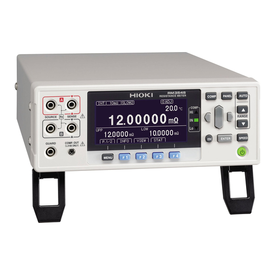
1.2 Names and Functions of Parts 1.2 Names and Functions of Parts Front Panel Viewing Measured Viewing Comparator Results Values and Settings COMP indicator LEDs Indicate the judgment result of the measured value (p.98). Display Screen (Mono- chrome graphical LCD) Measured value is above upper limit Pass (meets criteria) Display of measurements and... -
Page 31: Measurement
Rear Panel RM3545-01 Switching between GP-IB Communications NPN and PNP GP-IB Connector EXT I/O NPN/PNP switch (RM3545-01 only) Left : Current sink (NPN) Connect to a computer, or other device Right: Current source (PNP) (p.228) Connecting Sending and the Power... - Page 32 1.2 Names and Functions of Parts RM3545-02 Using the Multiplexer Unit Multiplexer Unit Slot (RM3545-02 only) Installing the Z3003 Multiplexer Unit (up to 2 units) (p.42) Bottom Panel This instrument can be rack mounted. See: "Appendix 17 Rack Mounting" (p. A35) Parts removed from this instrument should be stored in a safe place to enable future reuse.
-
Page 33: Measurement Process
1.3 Measurement Process 1.3 Measurement Process Install the Multiplexer Unit (RM3545-02; as necessary) Rear Panel Front Panel Connect the external interface Install this instrument (p. 6) (as needed) Using the printer (p.237) • Using the USB, RS-232C or GP-IB •... -
Page 34: Appendix 11Measuring Contact Resistance
1.3 Measurement Process *1 About zero-adjustment Perform zero-adjustment in the following circumstances: The measured value is not cleared due to thermal EMF or other factors. • → The measured value will be adjusted to zero. (*2) Four-terminal connection (called Kelvin connection) is difficult. •... -
Page 35: Screen Organization And Operation Overview
1.4 Screen Organization and Operation Overview 1.4 Screen Organization and Operation Overview The instrument’s screen interface consists of a Measurement screen and various Settings screens. The screen examples in this guide appear reversed (black on white) for best visibility on the printed page. -
Page 36: Compliant Resistance Measure- Ment
1.4 Screen Organization and Operation Overview When the scan function is set to auto or step (RM3545-02 only) Individual channels’ comparator result (If a measured value fault occurs, a description of the error is displayed.) Individual channels’ measured value Total judgment result Channel number Individual channels’... -
Page 37: Measurement
1.4 Screen Organization and Operation Overview (4) Settings screen Move to the [MEAS], [SYS], [I/O], [IF], [BIN], [MUX1], or [MUX2] tab.* * MUX1/MUX2 is only displayed on the RM3545-02. Move among Select a settings. setting. Switch functions with an F key or set values. -
Page 38: Measurement
Measurement range (p.49) ▲▼ (RANGE) SPEED Measurement speed (p.50) Measurement screen (p.54) INFO (F1) Display setting conditions (P.1/2) (For the RM3545-02, P.1/3) Switch measurement screen (p.52) VIEW (F2) display Display statistical calcula- STAT (F3) (p.111) tion results STOP (F3) Stop scan... -
Page 39: Measurement
1.4 Screen Organization and Operation Overview Screen Setting and key Overview Settings Measurement 0 ADJUST Clear zero-adjustment (p.71) screen Setting screen TC SET Temperature correction (p.75) (SETTING) (MEAS) ΔT R0, T0 Temperature conversion (p.116) DELAY Delay (p.84) AVERAGE Averaging (p.73) AUTO HOLD Hold measured value (p.60) -
Page 40: Measurement
DATA OUT CMD MONITOR PRINT INTRVL PRINT COLUMN Printing (p.237) STAT CLEAR BIN Setting screen BIN measurement settings (p.108) (BIN) *1 RM3545-01 only *2 RM3545-02 only *3 When using the multiplexer, the selected channel number will be displayed next to “MEAS.”... -
Page 41: Checking The Measurement Target
1.5 Checking the Measurement Target 1.5 Checking the Measurement Target To carry out proper resistance measurement, change the measurement conditions appro- priately according to the measurement target. Before starting measurement, use the exam- ples recommended in the following table to configure the instrument. Recommended settings (Bold indicates a change from the factory default.) Measurement target... -
Page 42: Measurement
1.5 Checking the Measurement Target... -
Page 43: Chapter 2 Measurement Preparations
2.1 Connecting the Power Cord Measurement Chapter 2 Preparations Be sure to read the "Operating Precautions" (p.6) before installing and connecting this instrument. Refer to "Appendix 17 Rack Mounting" (p. A35) for rack mounting. 2.1 Connecting the Power Cord Turn off the power before disconnecting the power cord. Rear Panel Power inlet Confirm that the instrument's Main power... -
Page 44: Connecting Measurement Leads
2.2 Connecting Measurement Leads 2.2 Connecting Measurement Leads Connect the included or optional Hioki measurement leads to the measurement terminals. Before connecting the measurement leads, read "Operating Precautions" (p.6) carefully. Refer to "Options" (p.3) for details. We recommend using optional Hioki measurement leads. -
Page 45: Connecting Z2001 Temperature Sensor Or Thermometer With Analog Output (When Using The Tc Or Δt)
2.3 Connecting Z2001 Temperature Sensor or Thermometer with Analog Output (When using 2.3 Connecting Z2001 Temperature Sensor or Thermometer with Analog Output (When using the TC or ΔT) Connecting the Z2001 Temperature Sensor Before connecting the temperature sensor, read "Operating Precautions" (p.6) carefully. Connection Methods Connecting the Z2001 Temperature Sensor Rear Panel... -
Page 46: Measurement
2.3 Connecting Z2001 Temperature Sensor or Thermometer with Analog Output (When using After turning on the instrument, check whether the temperature measurement settings are correct. Change if necessary. Open the Settings Screen. Switch the function menu to P.2/3. The Settings screen appears. -
Page 47: Measurement
2.3 Connecting Z2001 Temperature Sensor or Thermometer with Analog Output (When using Connecting an Analog Output Thermometer To measure temperature, connect the analog output thermometer to the instrument. Before connecting the thermometer, read "Operating Precautions" (p.6) carefully. Connection Methods Connecting an Analog Output Thermometer Rear Panel TEMP.ANALOG INPUT terminal block Confirm that the instrument's Main... -
Page 48: Measurement
2.3 Connecting Z2001 Temperature Sensor or Thermometer with Analog Output (When using After turning on the instrument, check whether the temperature measurement settings are correct. Change if necessary. Open the Settings Screen. Switch the function menu to P.2/3. The Settings screen appears. -
Page 49: Measurement
2.3 Connecting Z2001 Temperature Sensor or Thermometer with Analog Output (When using Set two reference voltages and the corresponding reference temperatures. Set reference voltages V and V and reference temperatures T and T by following Steps through for each. Move the cursor to the setting you wish to configure. -
Page 50: Installing The Multiplexer Unit
2.4 Installing the Multiplexer Unit 2.4 Installing the Multiplexer Unit To use multiplexing capability, you must first install the Z3003 Multiplexer Unit. Before connecting the Multiplexer Unit, read "Operating Precautions" (p.6) carefully. Installing a Multiplexer Unit Rear panel UNIT 1 UNIT 2 Required item: One Phillips-head screwdriver Turn off the instrument’s main power... -
Page 51: Turning The Power On And Off
2.5 Turning the Power On and Off 2.5 Turning the Power On and Off Turning On the Instrument with the Main Power Switch Turn on ( ) the main power switch on the rear of the instrument. If the main power switch was turned off while the instrument was not in the standby state, the standby state will be automatically canceled when the main power switch is turned on. -
Page 52: Placing The Instrument In The Standby State
• Firmware versions • Communication interface setting • Detected line frequency • EXT I/O (NPN/PNP) setting • Self-Calibration setting • Inserted unit information (RM3545-02 only) No Errors Error Indicates an error (p. 296). Normal display (measurement screen) No self-test is performed for the Z3003 Multiplexer Unit on startup. -
Page 53: Pre-Operation Inspection
Before using the instrument for the first time, verify that it operates normally to ensure that no damage occurred during storage or shipping. If you find any dam- age, contact your authorized Hioki distributor or reseller. Peripheral Device Inspection Metal Exposed... - Page 54 2.6 Pre-Operation Inspection...
-
Page 55: Chapter 3 Basic Measurements
Basic Measurements Chapter 3 Before making measurements, read "Operating Precautions" (p. 16) carefully. This chapter explains basic operating procedures for the instrument. "3.1 Checking the Measurement Target" (p.48) "3.2 Selecting the Measurement Range" (p.49) "3.3 Setting the Measurement Speed" (p.50) "3.4 Connecting Measurement Leads to the Measurement Target"... -
Page 56: Checking The Measurement Target
3.1 Checking the Measurement Target 3.1 Checking the Measurement Target To carry out proper resistance measurement, change the measurement conditions appro- priately according to the measurement target. Before starting measurement, use the exam- ples recommended in the following table to configure the instrument. Recommended settings (Bold indicates a change from the factory default.) Measurement target... -
Page 57: Selecting The Measurement Range
3.2 Selecting the Measurement Range 3.2 Selecting the Measurement Range The measurement range can be set as follows. Auto-ranging (the AUTO range) can also be selected. Manual Range Setting Select the range to use. (AUTO off) The decimal point location and unit indicator change with each key press. -
Page 58: Setting The Measurement Speed
3.3 Setting the Measurement Speed 3.3 Setting the Measurement Speed The measurement speed can be set to FAST, MED (medium), SLOW1, or SLOW2. The MED (medium), SLOW1, and SLOW2 settings offer increased measurement precision compared to the FAST setting as well as greater resistance to the effects of the external environment. -
Page 59: Connecting Measurement Leads To The Measurement Target
3.4 Connecting Measurement Leads to the Measurement Target 3.4 Connecting Measurement Leads to the Mea- surement Target Before making measurements, read "Operating Precautions" (p.6) carefully. Example with L2101 Example with L2102 (Place leads in contact with target.) Example with L2104 SOURCE A SENSE A SENSE B... -
Page 60: Checking Measured Values
3.5 Checking Measured Values 3.5 Checking Measured Values The resistance value will be displayed. If the display does not indicate the mea- • sured value, see "Confirming Measure- ment Faults" (p. 55). To convert the value into a parameter • other than resistance, see below. - Page 61 3.5 Checking Measured Values Example displays Display of pre-calculation measured values varies with the settings. (No display) (Temperature display) (Value before TC calculation (Value before scaling calculation : With TC ON) : With scaling ON) Rt: Resistance measured value R: Resistance measured value before TC calculation before scaling (Value before REF% calculation...
-
Page 62: Measurement
3.5 Checking Measured Values Displaying a list of measurement conditions and settings Display the measurement conditions. Switch the function menu to P.1/2. [INFO] Display measurement conditions. Check the measurement conditions. If the interface type has been set to "printer," you can print settings with Return to the Measurement screen. -
Page 63: Confirming Measurement Faults
3.5 Checking Measured Values Confirming Measurement Faults When a measurement is not performed correctly, a measurement fault indicator appears and a ERR signal of the EXT I/O is output (no ERR signal is output for over-range or unmeasured events). Operation when a current fault occurs can be changed with the set- tings. -
Page 64: Measurement
3.5 Checking Measured Values Temperature sensor not connected Temperature measurement cannot be performed because the temperature sensor has not Display been connected. There is no need to connect the temperature sensor when not using tem- perature correction or ΔT. Switch the display if you do not wish to display the temperature. - - . -
Page 65: Measurement
3.5 Checking Measured Values *1 Over-range Detection Function Examples of Over-range Faults Over-range Detection Measurement Example The measured value is outside of Attempting to measure 13 kΩ with the 10 kΩ range selected the measurement range. The relative tolerance (%) display Measuring 500 Ω... -
Page 66: Measurement
3.5 Checking Measured Values LP OFF 100 MΩ range SOURCE B - SOURCE A Current Measurement Range high-precision (Other than measurement switching Current mode target) * − − 1.5 Ω 10 mΩ 1.5 Ω − 100 mΩ High − 15 Ω 100 mΩ... -
Page 67: Measurement
Hi results. Choose the setting that best suits your application. The current fault mode setting applies to all channels. (RM3545-02 only) Open the Settings Screen. -
Page 68: Holding Measured Values
The auto-hold function provides a convenient way to check measured values. Once the measured value stabilizes, the beeper will sound, and the value will be automatically held. The auto-hold function setting applies to all channels. (RM3545-02 only) Open the Settings Screen. -
Page 69: Measurement
3.5 Checking Measured Values Canceling auto-hold operation Hold operation is automatically canceled when the measurement leads are removed from the measurement target and then brought into contact with the measurement target again. You can also cancel hold operation by pressing or changing the range and measure- ment speed. - Page 70 3.5 Checking Measured Values...
-
Page 71: Chapter 4 Customizing Measurement Conditions
Customizing Measurement Chapter 4 Conditions Before making measurements, read "Operating Precautions" (p. 16) carefully. This chapter explains functionality employed to make more advanced, more accurate mea- surements. The following table lists functions and example uses: Example uses Function When you wish to convert resistance values based on a Temperature Correction (TC) p.75... -
Page 72: Switching To Low-Power Resistance Measurement
4.1 Switching to Low-power Resistance Measurement 4.1 Switching to Low-power Resistance Measurement In low-power resistance measurement, the open terminal voltage is limited to 20 mV to allow measurement with an extremely low current. When measuring signal contacts (wire harnesses, connectors, relay contacts, or switches), the low-power resistance measurement function can be used to minimize the effect on the contact state. - Page 73 4.1 Switching to Low-power Resistance Measurement Open the Settings Screen. Switch the function menu to P.2/3. The Settings screen appears. Open the Measurement Setting Screen. Move cursor [MEAS] tab with the left and right cursor keys. Select the low-power mode, as needed. Selection Low-power resistance...
-
Page 74: Switching Measurement Currents (100 Mω To 100 Ω)
4.2 Switching Measurement Currents (100 mΩ to 100 Ω) 4.2 Switching Measurement Currents (100 mΩ to 100 Ω) Power equivalent to the resistance value × (measurement current) will be applied to the measurement target. If there are any of the following concerns, depending on the level of the measurement current, set the measurement current to low. - Page 75 4.2 Switching Measurement Currents (100 mΩ to 100 Ω) Open the Settings Screen. Switch the function menu to P.2/3. The Settings screen appears. Open the Measurement Setting Screen. Move cursor [MEAS] tab with the left and right cursor keys. Select the 100 mΩ range measurement current. Selection HIGH (default) Return to the Measurement screen.
-
Page 76: Zero Adjustment
4.3 Zero Adjustment 4.3 Zero Adjustment Perform zero-adjustment in the following circumstances: When you wish to increase the measurement precision • → For some ranges, there may be a component added to the accuracy if zero-adjust- ment is not performed. See: "Measurement Specifications"... - Page 77 4.3 Zero Adjustment If a resistance that is smaller than the resistance value when zero-adjustment was per- • formed is measured, the measured value will be negative. Example: If you set an offset of 50 mΩ for the 100 mΩ range →If you measure 30 mΩ, -20 mΩ...
- Page 78 4.3 Zero Adjustment Verify that the measured value is within ±1%f.s. If the measured value is 50%f.s. or less in each range, zero-adjustment can be performed, but a warn- ing will be issued when it is greater than 1%f.s. If no measured value is displayed, verify whether the measurement leads have been wired properly.
- Page 79 4.3 Zero Adjustment Zero Adjustment Faults If zero adjustment fails, the following error message appears. Before attempting zero adjustment again, confirm the following: Verify that the measured value is -1%f.s. to 50%f.s. in each range. • When using measurement leads that you made, reduce the wiring resistance. •...
- Page 80 4.3 Zero Adjustment Select 0 ADJUST. Selection Cancel zero-adjustment. A confirmation message will be displayed. Confirm and return to the Mea- surement screen. Clear zero-adjustment and return Settings screen. Cancel the operation and return previous screen. Return to the Measurement screen. Return to the Measurement screen.
-
Page 81: Stabilizing Measured Values (Averaging Function)
4.4 Stabilizing Measured Values (Averaging Function) 4.4 Stabilizing Measured Values (Averaging Function) The averaging function averages multiple measured values and displays the results. It can be used to reduce variation in measured values. For internal trigger measurement (Free-Run), a moving average is calculated. For external trigger measurement (and command operation) (Non-Free-Run), a :READ? - Page 82 4.4 Stabilizing Measured Values (Averaging Function) Enable the averaging function. Selection Enables the averaging function Disables the averaging function (default) (go to step 5) Set the number of averaging iterations. Move the cursor to the setting you wish to configure. Make the value editable with the key.
-
Page 83: Correcting For The Effects Of Temperature (Temperature Correction (Tc))
4.5 Correcting for the Effects of Temperature (Temperature Correction (TC)) 4.5 Correcting for the Effects of Temperature (Temperature Correction (TC)) Temperature correction converts resistance values to resistance values at standard tem- perature and displays the result. For more information about the principle of temperature correction, see "Appendix 4 Tem- perature Correction (TC) Function"... - Page 84 4.5 Correcting for the Effects of Temperature (Temperature Correction (TC)) Set the reference temperature and temperature coefficient. (Set the reference temperature and temperature coefficient by following steps through for each.) Move the cursor to the setting you wish to configure. Make the value editable with the key.
-
Page 85: Correcting Measured Values And Displaying Physical Properties Other Than Resistance Values (Scaling Function)
4.6 Correcting Measured Values and Displaying Physical Properties Other than Resistance 4.6 Correcting Measured Values and Displaying Physical Properties Other than Resistance Values (Scaling Function) This function applies a correction to measured values. It can be used to cancel the effects of the probing position or differences between measuring instruments, or to apply a user- specified offset as an alternative to zero-adjustment. - Page 86 4.6 Correcting Measured Values and Displaying Physical Properties Other than Resistance Open the Settings Screen. Switch the function menu to P.2/3. The Settings screen appears. Open the Measurement Setting Screen. Move cursor [MEAS] tab with the left and right cursor keys. Enable the scaling function.
- Page 87 4.6 Correcting Measured Values and Displaying Physical Properties Other than Resistance Set the gain coefficient. Move the cursor to the setting you wish to configure. Make the value editable with the key. Move among Change digits. values. Move the cursor to the digit you wish to set with the left and right cursor keys.
- Page 88 4.6 Correcting Measured Values and Displaying Physical Properties Other than Resistance Set the units for the displayed measured values. Selection Use Ω as the unit. (default) (go to step 8) Eliminate the unit. (go to step 8) Use a user-defined unit. Edit the unit as desired.
-
Page 89: Changing The Number Of Measured Value Digits
4.7 Changing the Number of Measured Value Digits 4.7 Changing the Number of Measured Value Digits The number of measured value digits setting applies to all channels. (RM3545-02 only) Open the Settings Screen. Switch the function menu to P.2/3. The Settings screen appears. -
Page 90: Compensating For Thermal Emf Offset (Offset Voltage Compensation - Ovc)
4.8 Compensating for Thermal EMF Offset (Offset Voltage Compensation - OVC) 4.8 Compensating for Thermal EMF Offset (Offset Voltage Compensation - OVC) This function automatically compensates for offset voltage resulting from thermal emf or internal instrument bias. (OVC: Offset Voltage Compensation) See: "Appendix 9 Effect of Thermal EMF"... - Page 91 4.8 Compensating for Thermal EMF Offset (Offset Voltage Compensation - OVC) Enable the offset voltage compensation (OVC) function. Selection Return to the Measurement screen. Return to the Measurement screen. When the measurement target has a high inductance, it is necessary to adjust the delay •...
-
Page 92: Setting Pre-Measurement Delay
4.9 Setting Pre-Measurement Delay 4.9 Setting Pre-Measurement Delay This function adjusts the time for measurement to stabilize by inserting a waiting period after use of the OVC or the auto range function to change the measurement current. When this function is used, the instrument waits for its internal circuitry to stabilize before starting measurement, even if the measurement target has a high reactance component. - Page 93 4.9 Setting Pre-Measurement Delay Delay Timing Chart Contact Separation Probe Contact Condition Measurement Current Detected voltage Measurement Measurement processing The preset value is set assuming about 10 mH of inductance and varies with each mea- • surement range. When using the EXT trigger source, the measurement current will not be stopped for •...
- Page 94 4.9 Setting Pre-Measurement Delay Setting the Delay Time Set the delay so that reactance component (inductance or capacitance) does not affect measurements. To fine tune the delay, begin with a longer delay than necessary, then gradually shorten it while watching the measured value. Open the Settings Screen.
- Page 95 4.9 Setting Pre-Measurement Delay Set DELAY. Move the cursor to the setting you wish to configure. Make the value editable with the key. Move among Change digits. values. Move the cursor to the digit you wish to set with the left and right cursor keys.
-
Page 96: Checking For Poor Or Improper Contact (Contact Check Function)
4.10 Checking for Poor or Improper Contact (Contact Check Function) 4.10 Checking for Poor or Improper Contact (Contact Check Function) This function detects poor contact between the probes and measurement target, and bro- ken measurement cables. The instrument continually monitors the resistance between the SOURCE A and SENSE A probes and the SOURCE B and SENSE B probes from the start of integration (including response time) and while measuring. - Page 97 4.10 Checking for Poor or Improper Contact (Contact Check Function) Open the Settings Screen. Switch the function menu to P.2/3. The Settings screen appears. Open the Measurement Setting Screen. Move cursor [MEAS] tab with the left and right cursor keys. Enable the Contact Check function.
-
Page 98: Improving Probe Contact (Contact Improver Function)
4.11 Improving Probe Contact (Contact Improver Function) 4.11 Improving Probe Contact (Contact Improver Function) Probe contacts can be improved by applying current from the SENSE A to the SENSE B probes before measuring. The Contact Improver function applies voltage to the sample. Be careful when measuring samples with characteristics (magnetoresistive elements, signal relays, EMI filters, etc.) that may be affected. - Page 99 4.11 Improving Probe Contact (Contact Improver Function) Open the Measurement Setting Screen. Move cursor [MEAS] tab with the left and right cursor keys. Enable the Contact Improver function. Selection Enables the contact improver function Disables the contact improver (default) Return to the Measurement screen. Return to the Measurement screen.
-
Page 100: Maintaining Measurement Precision (Self-Calibration)
4.12 Maintaining Measurement Precision (Self-Calibration) 4.12 Maintaining Measurement Precision (Self-Calibration) The instrument corrects the circuitry’s internal offset voltage and gain drift as a form of self- calibration in order to maintain its measurement precision. You can select between two self-calibration function execution methods. Configure automatically. - Page 101 4.12 Maintaining Measurement Precision (Self-Calibration) Open the System Setting Screen. Move the cursor to the [SYS] tab with the left and right cur- sor keys. Configure self-calibration operation. Selection Configure automatically. (default) Configure manually. Return to the Measurement screen. Return to the Measurement screen.
- Page 102 4.12 Maintaining Measurement Precision (Self-Calibration) Auto setting operation Self-calibration starts immediately after measurement completes and is finished in 5 ms. One TRIG signal received during self-calibration is held, and measurement will start after the self-calibration completes. If there is at least 5 ms of extra time in the measurement interval Measurement Self- Self-...
- Page 103 4.12 Maintaining Measurement Precision (Self-Calibration) Manual setting operation Self-calibration starts immediately when the CAL signal is input. If the TRIG signal is input during self-calibration, self-calibration will continue. In this case, the TRIG signal will be accepted, the EOM signal will turn off, and measurement will start after self-calibration completes.
-
Page 104: Increasing The Precision Of The 100 Mω Range (100 Mω High-Precision Mode)
4.13 Increasing the Precision of the 100 MΩ Range (100 MΩ High-precision Mode) 4.13 Increasing the Precision of the 100 MΩ Range (100 MΩ High-precision Mode) The precision of the 100 MΩ range can be increased. Turning on high-precision mode has the following effects: The 1,000 MΩ... -
Page 105: Chapter 5 Judgment, Statistics
Judgment, Statistics, and Conversion Chapter 5 Functions This chapter explains measured value judgments and conversion functions. "5.1 Judging Measured Values (Comparator Function)" (p. 98) "5.2 Classifying Measurement Results (BIN Measurement Function)" (p. 108) "5.3 Performing Statistical Calculations on Measured Values" (p. 111) "5.4 Performing Temperature Rise Test (Temperature Conversion Function (ΔT))"... -
Page 106: Judging Measured Values (Comparator Function)
5.1 Judging Measured Values (Comparator Function) 5.1 Judging Measured Values (Comparator Function) The comparator function provides the following capabilities: Displaying information on the instrument (COMP lamp Hi/ IN/ Lo) • Measured value > Upper limit value Upper limit value ≥ Measured value ≥ Lower limit value Measured value <... - Page 107 5.1 Judging Measured Values (Comparator Function) Before Using the Comparator Function The comparator judgment indicator will function as follows for over-range events • (“ ” display) and measurement faults (“CONTACT TERM” display or “ ” dis- OvrRng - - - - - - - play): See: "Confirming Measurement Faults"(p.55)
-
Page 108: Enabling And Disabling The Comparator Function
5.1 Judging Measured Values (Comparator Function) Enabling and Disabling the Comparator Function The comparator function is disabled by default. When the function is disabled, comparator settings are ignored. Open the Comparator Settings screen. The Comparator Settings screen appears. Enable or disable the comparator function. Switch the comparator function ON or OFF. -
Page 109: Decide According To Upper/Lower Thresholds (Abs Mode)
5.1 Judging Measured Values (Comparator Function) Decide According to Upper/Lower Thresholds (ABS Mode) Setting example: Upper threshold 12 mΩ, lower threshold 10 mΩ To abort the setting process, press . Settings are abandoned and the display returns to the pre- vious screen. - Page 110 5.1 Judging Measured Values (Comparator Function) Set the negative tolerance in the same way. Accept the settings and return to the Measurement screen.
-
Page 111: Decide According To Reference Value And Tolerance (Ref% Mode)
5.1 Judging Measured Values (Comparator Function) Decide According to Reference Value and Tolerance (REF% Mode) When REF% mode is enabled, the measured value will be displayed as an absolute value (%). Measured Value Relative Value = × 100 [%] Setting range: -99.999% to +99.999% Reference (tolerance) Value... - Page 112 5.1 Judging Measured Values (Comparator Function) Set the allowable range (upper and lower limit values). Move among Change digits. values. Move the cursor to the digit you wish to set with the left and right cursor keys. Change the value with the up and down cursor keys.
-
Page 113: Checking Judgments Using Sound (Judgment Sound Setting Function)
5.1 Judging Measured Values (Comparator Function) Checking Judgments Using Sound (Judgment Sound Setting Function) The comparator judgment beeper can be enabled and disabled. The judgment beeper is disabled (OFF) by default. Separate judgment tones can be set for Hi, IN, and Lo judgments. When using the multiplexer, separate judgment tones can be set for PASS and FAIL judg- ments when the scan function is set to auto or step. - Page 114 5.1 Judging Measured Values (Comparator Function) Select the number of times to sound the beeper for Hi judgments. Move the cursor to the setting you wish to configure. To sound the beeper con- tinuously To set the number of beeps: Change the number of beeps.
-
Page 115: Checking Judgments With The L2105 Led Comparator Attachment (Option)
5.1 Judging Measured Values (Comparator Function) Checking Judgments with the L2105 LED Comparator Attachment (Option) By connecting the L2105 LED Comparator Attachment to the COMP.OUT jack, you can check judgment results easily at a distance from the instrument. The indicator will turn green for IN judgments and red for Hi and Lo judgments. -
Page 116: Classifying Measurement Results (Bin Measurement Function)
5.2 Classifying Measurement Results (BIN Measurement Function) 5.2 Classifying Measurement Results (BIN Measurement Function) BIN Measurement compares a measured value with up to ten sets of upper and lower thresholds (BIN 0 to BIN 9) in one operation, and display the results. Measured values that do not fall in any BIN are judged to be OB (out-of-bin). - Page 117 5.2 Classifying Measurement Results (BIN Measurement Function) Set the BIN number. Selection Select a BIN number. Set the BIN numbers. Move among Change digits. values. Move the cursor to the digit you wish to set with the left and right cursor keys.
- Page 118 5.2 Classifying Measurement Results (BIN Measurement Function) You can also display a list of set BIN numbers. BIN setting list display Return to the Measurement screen. Return to the Measurement screen. Return to the Measurement screen. When the BIN function is ON The BIN number with the IN judgment will be shown in re- verse video.
-
Page 119: Performing Statistical Calculations On Measured Values
5.3 Performing Statistical Calculations on Measured Values 5.3 Performing Statistical Calculations on Measured Values Statistical calculations can be performed on up to 30,000 measured values, with results dis- played. Printing is also available (p. 245). Calculation types: average, maximum and minimum values, population standard deviation, sample standard deviation, process compatibility indices In these formulas, n represents the number Maximum value Xmax = MAX (x... -
Page 120: Using Statistical Calculations
5.3 Performing Statistical Calculations on Measured Values Using Statistical Calculations Turning on the statistical calculation function causes statistics to be calculated based on the EXT I/O TRIG signal. The timing at which statistics are calculated for measured values varies with the trigger source setting. With external (EXT) triggering: If the TRIG signal is input, one measurement is performed •... - Page 121 5.3 Performing Statistical Calculations on Measured Values Enable the statistical calculation function. Selection Enable statistical calculation Disable statistical calcula- tion (default) Return to the Measurement screen. Return to the Measurement screen. When statistical calculation is ON, F3 [STAT] will be displayed when the MENU [P.1/3] display is active.
-
Page 122: Confirming, Printing, And Erasing Calculation Results
5.3 Performing Statistical Calculations on Measured Values Confirming, Printing, and Erasing Calculation Results Statistical calculation results are displayed on the screen. Additionally, results can be printed using an RS-232C printer. Once statistical calculation results have been printed, the data can be automatically deleted. Before printing, select the interface setting. - Page 123 5.3 Performing Statistical Calculations on Measured Values To print For more information about printing, see "Chapter 12 Printing (Using an RS-232C Printer)" (p.237) Output to the printer. "Example Printouts" (p. 247) To erase Erases the last measure- ment and calculation result (executes only once).
-
Page 124: Performing Temperature Rise Test (Temperature Conversion Function (Δt))
5.4 Performing Temperature Rise Test (Temperature Conversion Function (ΔT)) 5.4 Performing Temperature Rise Test (Temperature Conversion Function (ΔT)) The temperature conversion principle is used to derive temperature increase over time. This functionality allows the temperature during normal stops and other data to be esti- mated. - Page 125 5.4 Performing Temperature Rise Test (Temperature Conversion Function (ΔT)) Open the Settings Screen. Switch the function menu to P.2/3. The Settings screen appears. Open the Measurement Setting Screen. Move cursor [MEAS] tab with the left and right cursor keys. Enable the temperature conversion function. (ΔT) Selection Enables the function Disables the function...
- Page 126 5.4 Performing Temperature Rise Test (Temperature Conversion Function (ΔT)) Set the reciprocal (k) of the temperature coefficient at 0°C. Move the cursor to the setting you wish to configure. Make the value editable with the key. Move among Change digits. values.
-
Page 127: Chapter 6 Saving And Loading Panels
Saving and Loading Panels Chapter 6 (Saving and Loading Measurement Conditions) Current measurement conditions can be saved and loaded using the panel load function from the key operations, communications commands, or EXT-I/O. The instrument can save up to 30 sets (panel number: 1 to 30) of measurement conditions when not using the multiplexer or up to 8 sets (panel number: 31 to 38) when using the mul- tiplexer. -
Page 128: Saving Measurement Conditions (Panel Save Function)
6.1 Saving Measurement Conditions (Panel Save Function) 6.1 Saving Measurement Conditions (Panel Save Function) Open the Panel List Screen. The Panel List Screen appears. Save the measurement conditions. Selection Save the conditions. Enter the panel name. (If you enter the number of a previously saved panel, a warning message will be displayed.) Move Change... -
Page 129: Loading Measurement Conditions (Panel Load Function)
6.2 Loading Measurement Conditions (Panel Load Function) 6.2 Loading Measurement Conditions (Panel Load Function) Loads the measurement settings saved by the Panel Save function. By default, loading a panel causes zero-adjustment values to be loaded. If you do not wish to load zero-adjustment values, see "Preventing Loading of Zero-adjustment Val- ues"(p.122). -
Page 130: Preventing Loading Of Zero-Adjustment Values
6.2 Loading Measurement Conditions (Panel Load Function) Panels can also be loaded with the EXT I/O LOAD0 to LOAD5 control and communica- • tions commands. See: "Chapter 10 External Control (EXT I/O)"; "Input Signals" (p. 179) For more information about commands, see the included application disc. If measurement conditions are changed after being loaded, the panel name will no longer •... -
Page 131: Changing Panel Names
6.3 Changing Panel Names 6.3 Changing Panel Names Open the Panel List Screen. The Panel List Screen appears. Select a panel number. Selection Edit the panel name. Edit the panel name. Move Change among characters. characters. Move the cursor to the character you wish to set with the left and right cursor keys. -
Page 132: Deleting Panel Data
6.4 Deleting Panel Data 6.4 Deleting Panel Data Open the Panel List Screen. The Panel List Screen appears. Select a panel number. Selection Delete the panel. Verify that the confirmation message is shown and return to the Measurement screen. Delete the panel and switch to the previous screen (you can also do this with the key). -
Page 133: Chapter 7 System Settings
Chapter 7 System Settings This chapter describes system settings. "7.1 Disabling and Enabling Key Operations" (p. 126) "7.2 Enabling or Disabling the Key Beeper" (p. 128) "7.3 Power Line Frequency Manual Setting" (p. 129) "7.4 Adjusting Screen Contrast" (p. 131) "7.5 Adjusting the Backlight"... -
Page 134: Disabling And Enabling Key Operations
7.1 Disabling and Enabling Key Operations 7.1 Disabling and Enabling Key Operations Disabling Key Operations (Key-Lock Function) Activate the key-lock function to disable the instrument’s front panel key operations. Three key-lock levels are available to suit specific purposes. Disabling All Except Comparator Settings Only basic settings RANGE ▲▼... -
Page 135: Re-Enabling Key Operations (Key-Lock Cancel)
7.1 Disabling and Enabling Key Operations Enable or disable key operations. Disable all except key-lock cancel and return to the Measurement screen. Disable all except key-lock cancel and basic settings change and return to the Measurement screen. Return to the Measurement screen. -
Page 136: Enabling Or Disabling The Key Beeper
7.2 Enabling or Disabling the Key Beeper 7.2 Enabling or Disabling the Key Beeper The key beeper sound can be enabled and disabled. The key beeper is enabled (ON) by default. Open the Settings Screen. Switch the function menu to P.2/3. The Settings screen appears. -
Page 137: Power Line Frequency Manual Setting
7.3 Power Line Frequency Manual Setting 7.3 Power Line Frequency Manual Setting With the default setting (AUTO), the instrument attempts to automatically detect the line fre- quency, but manual setting is also available. Unless the line frequency is set correctly, measured values may be unstable. •... - Page 138 7.3 Power Line Frequency Manual Setting Select the line frequency being used. Selection Automatically detect local line frequency (default) When the line frequency is 50 Hz When the line frequency is 60 Hz Return to the Measurement screen. Return to the Measurement screen.
-
Page 139: Adjusting Screen Contrast
7.4 Adjusting Screen Contrast 7.4 Adjusting Screen Contrast The screen may become hard to see when ambient temperature changes. In this case, adjust the contrast. Open the Settings Screen. Switch the function menu to P.2/3. The Settings screen appears. Open the System Setting Screen. Move the cursor to the [SYS] tab with the left and right cur- sor keys. -
Page 140: Adjusting The Backlight
7.5 Adjusting the Backlight 7.5 Adjusting the Backlight Adjust backlight brightness to suit ambient illumination. When external (EXT) triggering is selected, backlight brightness is automatically reduced • after non-operation for one minute. Be aware that the display may be hard to see when brightness is set too low (near 0%). •... -
Page 141: Setting The Clock
7.6 Setting the Clock 7.6 Setting the Clock To record and print the correct time when using statistical calculations (p. 111), the clock needs to be set correctly. The time of printing is also output when printing statistical calcula- tion results. Open the Settings Screen. -
Page 142: Initializing (Reset)
7.7 Initializing (Reset) 7.7 Initializing (Reset) Three reset functions are available. For more information about communications commands, see the included application disc. Reset: Returns measurement conditions (except the panel data) to factory defaults. The instrument can be reset by three methods. Reset from the System setting screen •... - Page 143 7.7 Initializing (Reset) Select RESET. Selection Perform multiplexer channel reset. Perform a reset. Perform a system reset. Select whether to initialize the instrument. Execute Cancel the operation The Measurement screen is displayed when system reset finishes.
-
Page 144: Default Settings
(p.49) ▲▼ (RANGE) √ √ SPEED SLOW2 (p.50) Measurement screen (P.1/2) − (p.52) VIEW (F2) (For the RM3545-02, P.1/3) √ Measurement screen (P.2/2) 0 ADJ (F2) p.68) (For the RM3545-02, P.2/3) − LOCK (F3) (p.126) − Measurement Screen (P.3/3) FRONT (F1) FRONT −... - Page 145 SPEED 9600bps (p.224) screen (IF) − DATA OUT (p.234) − CMD MONITOR (p.231) BIN Setting − (p.108) screen (BIN) *1 RM3545-01 only *2 RM3545-02 only *3 When using the multiplexer, the selected channel number will be displayed next to “MEAS.”...
- Page 146 7.7 Initializing (Reset) Channel default values for the multiplexer are as follows: 4-wire UNIT TERM A TERM B Enabled TERM1 TERM2 Disabled TERM2 TERM3 Disabled TERM10 TERM11 Disabled TERM1 TERM2 Disabled TERM2 TERM3 Disabled TERM10 TERM11 Disabled TERM1 TERM2 Disabled TERM1 TERM2 Disabled...
-
Page 147: Chapter 8 Multiplexer
Chapter 8 Multiplexer By using the RM3545-02 in combination with the Z3003 Multiplexer Unit, it is possible to conduct measurements by switching among up to 20 locations (4-wire) or up to 42 locations (2-wire). When installing the multiplexer unit, be sure to read "2.4 Installing the Multiplexer Unit"(p.42). -
Page 148: About The Multiplexer
8.1 About the Multiplexer 8.1 About the Multiplexer Two Z3003 Multiplexer Units can be installed on the RM3545-02. Number of locations that can be measured Number of units 2-wire 4-wire 1 unit 21 locations 10 locations 2 units 42 locations... - Page 149 8.1 About the Multiplexer Scan function Step Auto The measurement location The measurement location is The measurement location is can be changed freely. switched according to a pre- switched according to a pre- Example uses viously set order. A single viously set order.
-
Page 150: Connector Type And Pinouts
8.1 About the Multiplexer Process up to multiplexer use Advance Connect the measurement cables to the multiplexer’s preparations connector. See: "Connector Type and Pinouts" (p.143) Enable the multiplexer and set the scan function. See: "Configuring Multiplexer Settings" (p.148) Set channel pin allocation. See: "Customizing Channel Pin Allocation"... -
Page 151: Connector Type And Pinouts
8.1 About the Multiplexer Connector Type and Pinouts Pinouts (Connector: D-SUB 50pin receptacle) 17 ..1 33 ..18 Connector: (Instrument Side) •... - Page 152 8.1 About the Multiplexer 2-wire Pin name Pin name Pin name TERM2 TERM9 TERM17 TERM1 TERM10 TERM18 TERM2 TERM11 TERM19 TERM3 TERM12 TERM20 TERM4 TERM11 TERM19 TERM3 TERM12 TERM20 TERM4 TERM13 TERM21 TERM5 TERM14 TERM22 TERM6 TERM13 TERM21 TERM5 TERM14 GUARD TERM6 TERM15...
-
Page 153: About Multiplexer Wiring
8.1 About the Multiplexer About multiplexer wiring Connect the multiplexer and measurement target as shown in the following diagram. • Z3003 Use shielded wires in the cables connected to the multiplexer connectors. Failure to do • so may cause measured values to be unstable due to the effects of noise. Connect cable shielding to the GUARD pin. -
Page 154: Internal Circuitry
Each terminal incorporates a built-in, protective fuse (rated current: 1.6 A). (Fuses cannot • be replaced by the customer.) If the fuse trips due to over-input, measurement will no lon- ger be possible. If this occurs, have the instrument repaired. RM3545-02 Follow current detection circuit switching... -
Page 155: Electrical Specifications
8.2 Internal Circuitry Electrical Specifications See: "13.2 Z3003 Multiplexer Unit"(p.277) (1) Measurement targets (wiring order is user-selected) 4-wire 10 locations (when using two Z3003 units, 20 locations) 2-wire 21 locations (when using two Z3003 units, 42 locations) (2) Measurable range Measurement current Instrument with Z3003: 1 A DC or less Externally connected device: 1 A DC or less, 100 mA AC or less... -
Page 156: Multiplexer Settings
8.3 Multiplexer Settings In addition to instrument key operation and communications commands, a sample applica- tion software is available for configuring multiplexer settings. The sample application software can be downloaded from the Hioki website (http:// www.hioki.com). Configuring Multiplexer Settings This section describes how to configure overall multiplexer operation. The measurement terminal and scan function settings can also be configured from the Measurement screen. - Page 157 8.3 Multiplexer Settings Set the measurement terminals. Selection Make measurements using the front measurement ter- minals (do not use the multi- plexer). (default) Use the multiplexer. Select the measurement method. Selection 4-wire (default) 2-wire When the measurement method is switched, the multiplexer channel settings will be initialized (i.e., a multiplexer channel reset will be performed).
- Page 158 8.3 Multiplexer Settings Select FAIL stop operation. This setting is valid only when the scan function is ON. Selection Stop scanning when any channel yields a FAIL judg- ment. Do not stop scanning even if a channel yields a FAIL judgment.
- Page 159 8.3 Multiplexer Settings When changing the measurement terminal setting or scan function setting on the Measurement screen Set the measurement terminals. Switch the function menu to P.3/3. Make measurements using the front measurement ter- minals (do not use the multi- plexer).
-
Page 160: Customizing Channel Pin Allocation
8.3 Multiplexer Settings Customizing Channel Pin Allocation The Multiplexer Unit can measure the resistance between user-specified pin pairs by changing the channel pin allocation. Pin allocation can be set for up to 42 channels. If you wish to initialize the multiplexer channel settings See: "7.7 Initializing (Reset)"(p.134) Channel default settings... - Page 161 8.3 Multiplexer Settings Setting the connection and measurement method for individual channels Open the Settings Screen. Switch the function menu to P.2/3. The Settings screen appears. Open the Multiplexer Channel Settings screen. Move cursor [MUX1] tab with the left and right cursor keys.
- Page 162 8.3 Multiplexer Settings Set the channels being used to ON. Move to the CH settings. Use the channel. Do not use the channel. Channels that have been set to OFF cannot be selected on the Measurement screen. Additionally, since channels set to OFF are ignored in scanning, they can- not be measured.
- Page 163 Set the terminal number. Set the measuring instrument for each channel. Move to INST selection. Measure resistance with the RM3545. Measure using an externally connected device. When the scan function is set to AUTO, channels that are set to an externally con- nected device will be ignored.
-
Page 164: Setting Basic Measurement Conditions And Total Judgment Conditions For Individual Channels
8.3 Multiplexer Settings Setting Basic Measurement Conditions and Total Judgment Conditions for Individual Channels Basic measurement conditions for individual channels can be set in list form. Total judgments After performing scan measurement, a total judgment is made based on the judgment results (comparator judgments) for individual channels. - Page 165 8.3 Multiplexer Settings Setting basic measurement conditions Open the Settings Screen. Switch the function menu to P.2/3. The Settings screen appears. Open the Multiplexer Basic Measurement Screen. Move cursor [MUX2] tab with the left and right cursor keys. Move to the channel you wish to set. Select the channel to set.
- Page 166 8.3 Multiplexer Settings Set the measurement speed. Move to the SPD (SPEED) parameter. Set the measurement speed to FAST. Set the measurement speed to MEDIUM. Set the measurement speed to SLOW1. Set the measurement speed to SLOW2. Set the measurement range. Move to the RANGE parameter.
- Page 167 8.3 Multiplexer Settings Set the comparator. 1. Determine the judgment method. Move to the UPP/REF parameter. Enable or disable compara- tor. Set the judgment mode to ABS (UPP, LOW). Set the judgment mode to REF%. Make the value editable. When using REF% mode and a channel other than CH1, you can use the CH1 mea- surement results as the reference value by pressing on MENU P.2/2.
-
Page 168: Customizing Measurement Conditions For Individual Channels
8.3 Multiplexer Settings Customizing Measurement Conditions for Individual Channels Set the measurement conditions for each channel. " See: Customizing Channel Pin Allocation" (p.152) If you wish to initialize the multiplexer channel settings See: "7.7 Initializing (Reset)"(p.134) Open the Settings Screen. Switch the function menu to P.2/3. -
Page 169: Measuring With The Multiplexer
8.4 Measuring with the Multiplexer 8.4 Measuring with the Multiplexer Measuring While Switching Channels Manually This section describes how to perform measurement while changing channels manually. Before configuring these settings, see "Configuring Multiplexer Settings" (p.148) and "Cus- tomizing Measurement Conditions for Individual Channels" (p.160). Turn off the scan function. -
Page 170: Performing Scan Measurement
8.4 Measuring with the Multiplexer Performing Scan Measurement This section describes how to measure channels in successive order. Before configuring these settings, see "Configuring Multiplexer Settings" (p.148) and "Cus- tomizing Measurement Conditions for Individual Channels" (p.160). Set the scan function to either auto or step. See: "Configuring Multiplexer Settings"... -
Page 171: Zero Adjustment (When A Multiplexer Unit Has Been Installed)
8.5 Zero Adjustment (When a Multiplexer Unit Has Been Installed) 8.5 Zero Adjustment (When a Multiplexer Unit Has Been Installed) Performing zero-adjustment Performing scanning zero-adjustment (when the scan function is set to auto or step only) Zero-adjustment will be performed for all selected channels. If there is a large number of enabled channels, this operation may take several dozens of seconds. -
Page 172: Canceling Zero-Adjustment
8.5 Zero Adjustment (When a Multiplexer Unit Has Been Installed) Canceling zero-adjustment Zero-adjustment can be canceled from either the Multiplexer Channel Settings screen or the Measurement Settings screen. Canceling zero-adjustment from the Multiplexer Channel Settings screen Open the Settings Screen. Switch the function menu to P.2/3. - Page 173 8.5 Zero Adjustment (When a Multiplexer Unit Has Been Installed) Canceling zero-adjustment from the Measurement Setting screen Open the Settings Screen. Switch the function menu to P.2/3. The Settings screen appears. Open the Measurement Setting Screen. Move cursor [MEAS] tab with the left and right cursor keys.
-
Page 174: Performing The Multiplexer Unit Self-Test
8.6 Performing the Multiplexer Unit Self-test 8.6 Performing the Multiplexer Unit Self-test This section describes how to verify proper Multiplexer Unit operation. Do not connect any measurement leads to the measurement terminals on the front of the instrument. Open the Settings Screen. Switch the function menu to P.2/3. -
Page 175: Example Connections And Settings
8.7 Example Connections and Settings 8.7 Example Connections and Settings Example network resistor settings MUX settings INST. UNIT TERM A TERM B RM3545 UNIT1 RM3545 UNIT1 RM3545 UNIT1 Example steering switch settings MUX settings INST. UNIT TERM A TERM B... - Page 176 8.7 Example Connections and Settings Example power switch settings MUX settings INST. UNIT TERM A TERM B RM3545 UNIT1 RM3545 UNIT1 RM3545 UNIT1 RM3545 UNIT1 RM3545 UNIT1 RM3545 UNIT1 RM3545 UNIT1 RM3545 UNIT1 (A step scan is used, with switches being switched between channels 2 and 3 and between channels 6 and 7.
- Page 177 8.7 Example Connections and Settings Example cable assembly (wire harness) settings MUX settings INST. UNIT TERM A TERM B RM3545 UNIT1 RM3545 UNIT1 RM3545 UNIT1 Example battery terminal weld settings MUX settings INST. UNIT TERM A TERM B RM3545 UNIT1...
- Page 178 8.7 Example Connections and Settings Example settings for a measurement target with high temperature dependence Using channel 1 (thermistor) measurement results as the comparator reference value MUX settings INST. UNIT TERM A TERM B RM3545 UNIT1 RM3545 UNIT1 RM3545 UNIT1 RM3545 UNIT1 MEAS settings...
- Page 179 8.7 Example Connections and Settings Example motor settings MUX settings INST. UNIT TERM A TERM B RM3545 UNIT1 RM3545 UNIT1 RM3545 UNIT1 RM3545 UNIT1 RM3545 UNIT1 RM3545 UNIT1 RM3545 UNIT1...
- Page 180 8.7 Example Connections and Settings Connecting an external device LCR Meter Battery Tester You can switch channels via the front panel, communications, or EXT I/O when using an external device, too.
-
Page 181: Chapter 9 D/A Output
Before using the instrument, read "Before Using D/A Output" (p.14) carefully. The Model RM3545, RM3545-01 and RM3545-02 are capable of generating D/A output for resistance measured values. By connecting D/A output to a logger or other device, it is pos- sible to easily record variations in resistance values. -
Page 182: D/A Output Specifications
9.2 D/A Output Specifications 9.2 D/A Output Specifications Output Resistance measured value (display value after zero-adjustment and temper- ature correction but before scaling and ΔT calculation) Output voltage 0 V (corresponds to 0 dgt.) to 1.5 V DC* If a measured value fault occurs, 1.5 V; if the measured value is negative, 0 V * For a 1,200,000 dgt. -
Page 183: Chapter 10 External Control (Ext I/O)
External Control Chapter 10 (EXT I/O) The EXT I/O connector on the rear of the instrument supports external control by providing output of the EOM and comparator judgment signals, and accepting input of TRIG and KEY_LOCK signals. All signals are isolated from the measurement circuit and ground. (I/O common pins are shared). -
Page 184: External Input/Output Connector And Signals
The NPN/PNP switch allows you to change the type of programmable controller that is sup- ported. The instrument ships with the switch set to the NPN position. See: "10.3 Internal Circuitry"(p.202) NPN/PNP switch setting RM3545 input circuit Supports sink output. Supports source output. RM3545 output circuit Non-polar Non-polar... -
Page 185: Connector Type And Signal Pinouts
10.1 External Input/Output Connector and Signals Connector Type and Signal Pinouts Before connecting a connector, see "Before Connecting EXT I/O" (p. 13). Use of EXT I/O enables the following control functionality: Measurement start (TRIG) → Measurement end (EOM, INDEX) • →... - Page 186 10.1 External Input/Output Connector and Signals Pin Signal name I/O Function Logic Pin Signal name I/O Function Logic External trigger TRIG, General-pur- Edge 20 0ADJ Zero adjust Edge pose input Self-calibration BCD_LOW Lower byte Level 21 Edge execution output Panel load KEY_LOCK Key-Lock Level 22...
-
Page 187: Signal Descriptions
10.1 External Input/Output Connector and Signals Only the RM3545-02 can be used for multiplexer-related control. • The 0ADJ signal should be asserted (ON) for at least 10 ms. • The connector's frame is connected to the instrument's rear panel (metal portions) as well •... - Page 188 10.1 External Input/Output Connector and Signals KEY_LOCK p.126 While the KEY_LOCK signal is held ON, all front panel keys (except standby key and ENTER (trigger) key) are disabled (key unlock and remote control cancellation operations are also disabled). p.183 The function of the LOAD signal (pins 4, 5, 6, 22, 23, 24) changes depending on the MUX signal.
- Page 189 10.1 External Input/Output Connector and Signals (3) Output Signals p.212 This signal indicates the end of measurement and zero-adjustment. At this point in time, the comparator judgment results and the ERR, BCD and BIN signals have been finalized. INDEX This signal indicates that A/D conversion in the measurement circuit is fin- ished.
- Page 190 10.1 External Input/Output Connector and Signals JUDGE mode and BCD mode Output signals operate under either JUDGE mode or BCD mode. The JUDGE mode output signals vary depending on whether the multiplexer is being used. In BCD mode, signals are used for both the upper and lower digits (and range information).
- Page 191 10.1 External Input/Output Connector and Signals (4) Signal correspondence chart LOAD0 to LOAD5 LOAD5 LOAD4 LOAD3 LOAD2 LOAD1 LOAD0 MUX signal OFF MUX signal ON − − Panel 1 Channel 1 Panel 2 Channel 2 Panel 3 Channel 3 Panel 4 Channel 4 Panel 5 Channel 5...
- Page 192 10.1 External Input/Output Connector and Signals RNG_OUT0 to RNG_OUT3 (when the BCD_LOW signal is ON) RNG_OUT3 RNG_OUT2 RNG_OUT1 RNG_OUT0 Range 10 mΩ 100 mΩ 1000 mΩ 10 Ω 100 Ω 1000 Ω 10 kΩ 100 kΩ 1000 kΩ 10 MΩ 100 MΩ...
-
Page 193: Timing Chart
10.2 Timing Chart Timing Chart 10.2 Each signal level indicates the ON/OFF state of a contact. When using the current source (PNP) setting, the level is the same as the EXT I/O pin voltage level. When using the cur- rent sink (NPN) setting, the high and low voltage levels are reversed. From Start of Measurement to Acquisition of Judgment Results (1) External trigger [EXT] setting (EOM output hold) When OVC is OFF... - Page 194 10.2 Timing Chart When OVC is ON TRIG Measurement Positive- Positive-direction Stopped currents direction application Negative-direction application application Delay Delay Check in Check in Contact check progress progress Measurement Measure- Measure- ment ment processing INDEX Judgment result/ BCD ON/OFF Judgment result/ BCD: HI, IN, LO, ERR, BCDm-n, RNG_OUT0 to 3 The measurement current will not be stopped for measurement ranges of 10 kΩ...
- Page 195 10.2 Timing Chart (2) External trigger [EXT] setting (EOM output pulse) The EOM signal turns ON at the end of measurement and then reverts to the OFF state once the time (t5) that has been set as the EOM pulse width elapses. TRIG t2+t3 (When OVC is ON, (t2+t3) ×...
- Page 196 10.2 Timing Chart Timing Chart Interval Descriptions Interval Description Duration Remarks Trigger Pulse 0.1 ms ON/ OFF-edge selectable Asserted (ON) or more Trigger Pulse 1 ms or more De-asserted (OFF) Delay 0 to 100 ms Setting-dependent Acquisition Integration time + Internal wait time processing time (see following table) Calculation time...
-
Page 197: Bcd Signal Timing
10.2 Timing Chart Internal wait time (unit: ms) (Processing time before and after integration measure- ment) reference values LP OFF 100 MΩ range Measurement Range Time high-precision mode Current − − 10 mΩ − High 100 mΩ − − High 1000 mΩ... - Page 198 10.2 Timing Chart Zero-adjustment timing 0ADJ 10 ms or more Zero-adjustment Zero-adjustment in progress processing INDEX For pulse EOM output, the EOM signal turns OFF when the pulse width time elapses. • When using the internal trigger [INT] setting, the EOM signal consists of pulse output with •...
- Page 199 10.2 Timing Chart Self-calibration timing For more information about the self-calibration function, see p.92. To maintain measurement precision, the instrument self-calibrates to compensate for inter- nal circuit offset voltage and gain drift. You can select between two self-calibration function execution methods. Configure automatically.
- Page 200 10.2 Timing Chart Auto setting operation Self-calibration starts immediately after measurement completes and is finished in 5 ms. One TRIG signal received during self-calibration is held, and measurement will start after the self-calibration completes. If there is at least 5 ms of extra time in the measurement interval Measurement Self- Measure-...
- Page 201 10.2 Timing Chart Manual setting operation Self-calibration starts immediately when the CAL signal is input. If the TRIG signal is input during self-calibration, self-calibration will continue. In this case, the TRIG signal will be accepted, the EOM signal will turn off, and measurement will start after self-calibration com- pletes.
-
Page 202: Contact Improver Timing
10.2 Timing Chart Contact improver timing For more information about the contact improver function, see p.90. Probe contacts can be improved by applying current between the sense terminals before measurement. The Contact Improver function applies voltage to the sample. Be careful when measuring samples with characteristics that may be affected. -
Page 203: Panel Load Timing
10.2 Timing Chart Panel Load Timing When using the multiplexer, set the MUX signal to ON. (1) When using the TRIG signal LOAD0 to LOAD5 Panel 1 Panel 2 Within 10 ms TRIG Processing time Panel 2 State Panel 1 Load processing Panel 2 Measurement... -
Page 204: Multiplexer Timing
10.2 Timing Chart Multiplexer Timing See: "8.3 Multiplexer Settings"(p.148) (1) Scan function: OFF To switch channels, set the MUX signal to ON. When using the TRIG signal LOAD0 to LOAD5 Channel 1 Channel 2 Within 10 ms TRIG Switching time Channel 2 State Channel 1... - Page 205 10.2 Timing Chart (2) Scan function: Auto Measurement is performed while switching all channels after one trigger input. Switching time Channel 1 Channel 20 Channel 1 Switching Switching Switching Switching State Measure- Measure- Measure- processing processing processing processing ment ment ment Judgment result/ Judgment result/ BCD: HI, IN, LO, ERR, PASS, FAIL, BCDm-n, RNG_OUT0 to 3...
- Page 206 10.2 Timing Chart (3) Scan function: Step After the trigger, processing switches to the next channel and measurement is performed. The total judgment (T_PASS, T_FAIL, T_ERR) signals are only output once measurement of the last channel is complete. Switching time Channel 1 Switching Channel 2...
-
Page 207: Output Signal State At Power-On
10.2 Timing Chart Channel switching time Without range or low-power switching Approx. 30 ms With range or low-power switching Approx. 50 ms When there is back EMF, for example due to a transformer, the relay hot-switching preven- tion function will increase the duration of switching processing. The hot-switching preven- tion function will be canceled after the back EMF has dissipated or after a maximum of (1 s + the set delay time) has elapsed. -
Page 208: Acquisition Process When Using An External Trigger
10.2 Timing Chart Acquisition Process When Using an External Trigger This section describes the process from measurement start to acquisition of judgment results or measured values when using an external trigger. The instrument outputs the EOM signal immediately once the judgment result (HI, IN, LO, ERR, T_PASS, T_FAIL, T_ERR) has been finalized. - Page 209 10.2 Timing Chart Measured value (BCD) acquisition processing when using an external trigger For BCD output, the upper and lower digits must be acquired separately. The upper and lower digits can be acquired in any order. In the following example, the upper digits are acquired first.
-
Page 210: Internal Circuitry
10.3 Internal Circuitry 10.3 Internal Circuitry PLC, etc. Input Circuit (NPN Setting) Output Common Internally Isolated Do not apply external power Common Signal Ground PLC, etc. Output Circuit (NPN Setting) Input Zener Voltage 30 V Common Internally Isolated Common Signal Ground Use ISO_COM as the common pin for both input and output signals. - Page 211 10.3 Internal Circuitry PLC, etc. Input Circuit Internally Isolated power (PNP Setting) Output Common Internally Isolated Do not apply external power Common Signal Ground Output Circuit PLC, etc. (PNP Setting) Input Zener Voltage 30 V Common Internally Isolated Common Signal Ground Use ISO_COM as the common pin for both input and output signals.
-
Page 212: Electrical Specifications
10.3 Internal Circuitry Electrical Specifications Input type Optocoupler-isolated, non-voltage contact inputs Input Signals (Current sink/source output compatible) Input asserted (ON) Residual voltage: 1 V or less (Input ON current: 4 mA (reference value)) Open (shutoff current: 100 μA or less) Input de-asserted (OFF) Output type Optocoupler-isolated, open drain output (non-polar) -
Page 213: Connection Examples
10.3 Internal Circuitry Connection Examples Input Circuit Connection Examples RM3545 RM3545 Input Input Switch Connections Relay Connections RM3545 RM3545 Input Input Output Output Common Common PLC Output (NPN Output) Connections PLC Output (PNP Output) Connections Output Circuit Connection Examples RM3545... -
Page 214: External I/O Settings
10.4 External I/O Settings 10.4 External I/O Settings The following external I/O settings are provided: Input settings Set the measurement start conditions (trigger source).(p.206) • Set the TRIG signal logic.(p.208) • Eliminate TRIG/PRINT signal chatter (filter function).(p.210) • Output settings Set the EOM signal.(p.212) •... - Page 215 10.4 External I/O Settings Switching the trigger source Open the Settings Screen. Switch the function menu to P.2/3. The Settings screen appears. Open the EXT I/O Setting Screen. Move the cursor to the [I/O] tab with the left and right cur- sor keys.
-
Page 216: Setting The Trig Signal Logic
10.4 External I/O Settings Setting the TRIG Signal Logic Select the ON or OFF edge as the logic at which the TRIG signal is enabled. When using the OFF edge, measurement times will be increased by approximately 0.2 ms. Open the Settings Screen. Switch the function menu to P.2/3. - Page 217 10.4 External I/O Settings ON edge and OFF edge operation ON edge • TRIG Measurement Measurement processing OFF edge • TRIG Measurement Measurement processing Measurement times will be 0.2 ms longer when using the OFF edge than when using the ON edge.
-
Page 218: Eliminating Trig/Print Signal Chatter (Filter Function)
10.4 External I/O Settings Eliminating TRIG/PRINT Signal Chatter (Filter Function) The filter function, which eliminates chatter, is useful when connecting a foot switch or sim- ilar device to the TRIG/PRINT signal. Open the Settings Screen. Switch the function menu to P.2/3. The Settings screen appears. - Page 219 10.4 External I/O Settings Set the response time. Move the cursor to the setting you wish to configure. Make the value editable with the key. Move among Change digits. values. Move the cursor to the digit you wish to set with the left and right cursor keys.
-
Page 220: Setting Eom Signal
10.4 External I/O Settings Setting EOM Signal You can select whether to hold EOM signal output until the next trigger is input or output a user-specified pulse width. When using the internal trigger [INT], the EOM pulse width is fixed at 5 ms, regardless of the settings. - Page 221 10.4 External I/O Settings (When PULSE is selected) Select the pulse width. Move the cursor to the setting you wish to configure. Make the value editable with the key. Move among Change digits. values. Move the cursor to the digit you wish to set with the left and right cursor keys.
-
Page 222: Switching Output Modes (Judge Mode/ Bcd Mode)
10.4 External I/O Settings Switching Output Modes (JUDGE Mode/ BCD Mode) Open the Settings Screen. Switch the function menu to P.2/3. The Settings screen appears. Open the EXT I/O Setting Screen. Move the cursor to the [I/O] tab with the left and right cur- sor keys. -
Page 223: Checking External Control
10.5 Checking External Control 10.5 Checking External Control Performing an I/O Test (EXT I/O Test Function) In addition to switching output signals ON and OFF manually, you can view the input signal state on the screen. Open the Settings Screen. Switch the function menu to P.2/3. - Page 224 10.5 Checking External Control Perform the EXT I/O test. Output signals Allows you to perform signal oper- ations. (ON: Reverse video; OFF: Normal display) : Select signal. : Turn signal ON. : Turn signal OFF. Input signals Displays the signal state. (ON: Reverse video;...
-
Page 225: Supplied Connector Assembly
10.6 Supplied Connector Assembly 10.6 Supplied Connector Assembly The EXT I/O connector and shell are supplied with the instrument. Assemble as shown below. Use shielded cables to connect a PLC to the EXT I/O connector. Using non-shielded con- • ductors may result in system errors from electrical noise. Connect the shield to the ISO_COM pin of the EXT I/O connector. - Page 226 10.6 Supplied Connector Assembly...
-
Page 227: Chapter 11 Communications
Acquiring Data" (p.230) (Data Output Function)" (p.234) *1 USB or RS-232C only. *2 The sample application can be downloaded from the Hioki website (http://www.hioki.com). Communications times There may be a display processing lag depending on the frequency and nature of any •... -
Page 228: Overview And Features
The I/O connector is a DTE (Data Terminal Equipment) configuration Recommended cables: 9637 RS-232C Cable(for PC) 9638 RS-232C Cable(for D-sub25pin connector) Operating Code: ASCII codes GP-IB Specifications (Interface Functions) (RM3545-01 only) All Source Handshake functions All Acceptor Handshake functions ... -
Page 229: Preparations Before Use (Connections And Settings)
11.2 Preparations before Use (Connections and Settings) 11.2 Preparations before Use (Connections and Settings) Using the USB Interface 1. Configuring USB Interface Communications Make these instrument settings. Open the Settings Screen. Switch the function menu to P.2/3. The Settings screen appears. - Page 230 USB driver. The following procedure need not be fol- lowed if the driver has already been installed, for example in the course of using another Hioki product. The USB driver can be found on the included application disc or down- loaded from the Hioki website (http://www.hioki.com).
- Page 231 Continue Anyway Procedure to uninstall the driver (uninstall the driver once it is no longer needed) Delete the Hioki USB CDC Driver using [Control Panel] - [Add or Remove Programs]. 3. Connect the USB cable. Connect the included USB cable to the instrument’s USB jack.
-
Page 232: Using The Rs-232C Interface
11.2 Preparations before Use (Connections and Settings) Using the RS-232C Interface 1. Configuring RS-232C Interface Communications Make these instrument settings. Open the Settings Screen. Switch the function menu to P.2/3. The Settings screen appears. Open the Communications Interface Setting Screen. Move the cursor to the [IF] tab with the left and right cursor keys. - Page 233 11.2 Preparations before Use (Connections and Settings) Select the interface transfer rate (baud rate). Selection 9600 (bps) (default) 19200 (bps) 38400 (bps) 115200 (bps) Return to the Measurement screen. Return to the Measure- ment screen, and enable the communications inter- face.
- Page 234 11.2 Preparations before Use (Connections and Settings) 2. Connect the RS-232C cable. Connect the RS-232C cable to the RS-232C connector. When connecting the cable, be sure to tighten the connector in place with screws. 1 2 3 4 5 Male 9-pin D-sub #4-40 attaching screws 6 7 8 9 To connect the instrument to a controller (DTE), use a cross-...
- Page 235 PC/AT-end Pin No. Pin No. Recommended cable: HIOKI Model 9637 RS-232C Cable (1.8 m) Connecting a controller with a 25-pin D-sub female port Use a crossover cable with a female 9-pin D-sub and a male 25-pin D-sub connector. As the figure shows, RTS and CTS pins are shorted together and crossed to DCD in the other connector.
-
Page 236: Using The Gp-Ib Interface (Rm3545-01 Only)
11.2 Preparations before Use (Connections and Settings) Using the GP-IB Interface (RM3545-01 only) 1. Configuring GP-IB Interface Communications Open the Settings Screen. Switch the function menu to P.2/3. The Settings screen appears. Open the Communications Interface Setting Screen. Move the cursor to the [IF] tab with the left and right cursor keys. - Page 237 “GP-IB” is only displayed on model RM3545-01 (equipped with GP-IB). 2. Connect the GP-IB cable. Connect the GP-IB cable to the GP-IB connector. When connecting the cable, be sure to tighten the connector in place with screws.
-
Page 238: Controlling The Instrument With Commands And Acquiring Data
11.3 Controlling the Instrument with Commands and Acquiring Data 11.3 Controlling the Instrument with Commands and Acquiring Data For more information about communications commands and query notation (from the com- munications message reference), see the Communications Command Instruction Manual on the included application disc. When creating programs, the communications monitor function can be used to display commands and their associated responses on the Mea- surement screen. -
Page 239: Displaying Communications Commands (Communications Monitor Function)
11.3 Controlling the Instrument with Commands and Acquiring Data Displaying Communications Commands (Communications Monitor Function) The communications monitor function can be used to display communications commands and query responses on the instrument’s screen. Open the Settings Screen. Switch the function menu to P.2/3. - Page 240 11.3 Controlling the Instrument with Commands and Acquiring Data Command and queries will be displayed on the bottom of the Measurement screen. Messages displayed in the communications monitor and their meanings If an error occurs during command execution, the following information will be displayed: Command error (improper command, improper argument format, etc.) •...
-
Page 241: Acquiring Measured Values At Once (Data Memory Function)
11.3 Controlling the Instrument with Commands and Acquiring Data Acquiring Measured Values at Once (Data Memory Function) Operation slows when measured values are acquired after each measurement. To avoid this delay, up to 50 measured values can be stored in memory and acquired at once later. Measured values are stored in memory as follows: Every time a measurement is performed by external (EXT) triggering •... -
Page 242: Auto-Exporting Measured Values (At End Of Measurement) (Data Output Function)
11.4 Auto-Exporting Measured Values (at End of Measurement) (Data Output Function) 11.4 Auto-Exporting Measured Values (at End of Measurement) (Data Output Function) Once measurement completes, the instrument can send measured values automatically as data to a computer via its UBS or RS-232C interface. There are two methods for sending data. - Page 243 11.4 Auto-Exporting Measured Values (at End of Measurement) (Data Output Function) Output data format Measured value format when scaling is off (The measured value format varies depending on scaling. (p.77)) Changing the number of digits in the measured value will not change the format. Undis- played digits have a value of 0.
- Page 244 11.4 Auto-Exporting Measured Values (at End of Measurement) (Data Output Function) Open the Settings Screen. Switch the function menu to P.2/3. The Settings screen appears. Open the Communications Interface Setting Screen. Move the cursor to the [IF] tab with the left and right cursor keys.
-
Page 245: Connecting The Printer To The Instrument
12.1 Connecting the Printer to the Instrument Printing Chapter 12 (Using an RS-232C Printer) Connecting Printing (p.240) Make instrument Make printer the printer to Measured values and • settings (p.239) settings the instrument comparator judgments List of measurement • conditions and set- tings Statistical calculation •... - Page 246 AC Adapter RS-232C Cable Connector Pinouts 1 2 3 4 5 13 ....... 1 25 ....... 14 6 7 8 9 RM3545 (9-pin) Connector Printer (25-pin) Connector (Example) Signal Signal Circuit name Circuit name Name Name Receive Data...
- Page 247 12.1 Connecting the Printer to the Instrument Instrument Settings Open the Settings Screen. Switch the function menu to P.2/3. The Settings screen appears. Open the Communications Interface Setting Screen. Move the cursor to the [IF] tab with the left and right cursor keys.
-
Page 248: Printing
12.2 Printing 12.2 Printing Before Printing Verify that the instrument settings (p.239) are correct. Printing Measured Values and Comparator Judgments Printing by key operation Pressing on Measurement screen P.1/3 causes the current measured value to [PRINT] be printed. When the temperature is not being displayed, only the resistance value will be printed. -
Page 249: Printing List Of Measurement Conditions And Settings
12.2 Printing Printing List of Measurement Conditions and Settings Pressing after pressing on Measurement screen P.1/3 to display a list of [INFO] settings prints a list of measurement conditions and settings. See: "Displaying a list of measurement conditions and settings" (p.54) Changing the number of columns printed per row Normally a row consists of one column, but you can also print three columns per row. - Page 250 12.2 Printing Select the number of print columns. Selection 1 column (default) 3 columns Return to the Measurement screen. Return to the Measurement screen.
- Page 251 12.2 Printing Interval printing You can automatically print measured values at a fixed time interval. Open the Settings Screen. Switch the function menu to P.2/3. The Settings screen appears. Open the Communications Interface Setting Screen. Move the cursor to the [IF] tab with the left and right cursor keys.
- Page 252 12.2 Printing Set the interval. Move the cursor to the setting you wish to configure. Make the value editable with the key. Move among Change digits. values. Move the cursor to the digit you wish to set with the left and right cursor keys.
-
Page 253: Printing Statistical Calculation Results
12.2 Printing Printing Statistical Calculation Results Statistical calculation results can be printed when statistical calculation is enabled (ON). To print, select PRINT on the screen or turn ON the instrument’s EXT I/O connector’s PRINT signal (short it with the ISO_GND pin). To enable statistical calculation: See: "5.3 Performing Statistical Calculations on Measured Values"... - Page 254 12.2 Printing Clearing statistical calculation results after each is printed You can clear statistical calculation results automatically after each is printed. Open the Settings Screen. Switch the function menu to P.2/3. The Settings screen appears. Open the Communications Interface Setting Screen. Move the cursor to the [IF] tab with the left and right cursor keys.
- Page 255 10.0004mOhm 00:00:01 10.0011mOhm 00:00:02 10.0001mOhm 00:00:03 10.0005mOhm 00:00:04 10.0000mOhm 00:00:05 10.0005mOhm Multiplexer scan results (RM3545-02 only) 2013-07-31 14:00:11 Total judge FAIL CH01 99.9758MOhm Hi FAIL CH02 9.9758MOhm IN PASS CH03 100.9758MOhm Lo PASS Do not print results during scanning.
- Page 256 12.2 Printing List of measurement conditions and settings MODEL RM3545-02 000000000 VER. 1.00 RANGE 10mOhm(1A) SPEED FAST DELAY 10ms A.HOLD OFF CALIB AUTO 0 ADJ SCALE LINE AUTO(60Hz) TRIG PRINT Statistical calculation results DATE - TIME 2013-07-31 14:01:11...
-
Page 257: Chapter 13 Specifications
Chapter 13 Specifications Chapter 13 Specifications 13.1 Instrument Specifications Measurement Ranges 100 MΩ range Number of Measurement range and f.s. high-precision ranges 0.000 00 mΩ (10 mΩ range) to 1200.0 MΩ (1000 MΩ range) 10 MΩ or lower range: f.s.=1,000,000dgt. 100 MΩ... -
Page 258: Measurement Specifications
Chapter 13 Specifications Measurement Specifications (1) Resistance Measurement Accuracy Conditions of guaranteed accuracy Warm-up time At least 60 minutes (When the instrument warms up for less than 60 minutes, measurement accuracy will be twice the value indicated in the accuracy table.) Temperature and hu- 23±5°C, 80%RH or less midity range for guar-... - Page 259 Chapter 13 Specifications Low Power: OFF Measure- Max. Measurement Accuracy 100MΩ Additional Max. ment Current open- range accuracy measure- termi- Range high- without ment FAST SLOW1 SLOW2 Switc precision 0ADJ range volt- (%rdg.+%f.s.) (%rdg.+%f.s.) (%rdg.+%f.s.) (%rdg.+%f.s.) hing mode (%f.s.) ∗2 0.060+0.050 0.060+0.020...
- Page 260 Chapter 13 Specifications ∗1 Negative values can be up to -10% full scale. The maximum display range is 9,999,999 dgt. or 9 GΩ. (If the maximum measurement range is exceeded, the over-range display will be shown even if the value is less than or equal to the maximum display range.) ∗2 •...
- Page 261 Chapter 13 Specifications : Integration time (unit: ms) (detected voltage data acquisition time) FAST MEDIUM Range SLOW1 SLOW2 50 Hz 60 Hz 50 Hz 60 Hz 1000 kΩ or less 0.3* 20.0 16.7 10 MΩ or more 20.0 16.7 20.0 16.7 All ranges 20.0...
- Page 262 Chapter 13 Specifications : Calculation time (unit: ms) Setting Time Statistical calculation : OFF Scaling : OFF Measured value display switching: None : Self-calibration time (unit: ms) Self-calibration setting Time Auto Manual : Number of average iterations (unit: iterations) Trigger source, continuous measurement Number of iterations When using the internal trigger source with continuous mea- surement on (free-run)
- Page 263 Chapter 13 Specifications Shortest measurement times when using the external trigger source or when continuous measure- ment off (non-free-run) LP OFF (unit: ms), tolerance: ±10%±0.2 ms, Values in parentheses on the second row apply when OVC is on. Measure- 100 MΩ range FAST MEDIUM Range...
- Page 264 Chapter 13 Specifications (2) Resistance D/A output accuracy Output accuracy Resistance measurement accuracy ±0.2%f.s. (temperature coefficient ±0.02%f.s./°C) Response time Measurement time + Max. 1 ms Shortest 2.0 ms (tolerance: ±10%±0.2 ms) Shortest conditions INT trigger source, LP: OFF, 1000 kΩ or lower range, Measurement speed: FAST, Delay: 0 ms, Self-Calibration: MANUAL (3) Temperature measurement accuracy (Thermistor sensor)
-
Page 265: About Instrument Accuracy
Chapter 13 Specifications About Instrument Accuracy We define measurement tolerances in terms of f.s. (full scale), rdg. (reading) and dgt. (digit) values, with the following meanings. f.s. (maximum display value) This is usually the name of the maximum displayable value. For this instrument, it indicates the currently selected range. -
Page 266: Functions
Chapter 13 Specifications Functions (1) Resistance range switching function Mode AUTO/ MANUAL (Automatically set to manual if the comparator or BIN function is turned on.) Measurement Ranges LP OFF: 10 mΩ/ 100 mΩ/ 1000 mΩ/ 10 Ω/ 100 Ω/ 1000 Ω/ 10 kΩ/ 100 kΩ/ 1000 kΩ/ 10 MΩ/ 100 MΩ/ 1000 MΩ... - Page 267 Cancels the internal offset voltage and the surplus resistance. Setting ON/ OFF (clear): for each range Scan zero adjustment ON/ OFF: Set by channel. (RM3545-02 only) Adjustment range Within ±50%f.s. for each range (warning message displayed when in excess of ±1%f.s. for each range) Zero-adjustment cannot be used at 100 MΩ...
- Page 268 Chapter 13 Specifications (10)Delay Setting Operation Adjusts the time for measurement to stabilize by inserting a waiting period after using the OVC or the auto-range function to change the measurement current or after the TRIG signal. Preset: Integration starts after the factory-default time (which varies with the range) elapses.
- Page 269 Chapter 13 Specifications (11)Temperature measurement settings Temperature sensor Thermistor sensor/ Analog input types Analog input Formula − − 1 − − : Displayed value (°C) : Input voltage (V) : Reference voltage 1 (V) Setting range: 0.00 to 2.00 V : Reference temperature 1 (°C) Setting range: -99.9 to 999.9°C : Reference voltage 2 (V) Setting range: 0.00 to 2.00 V...
- Page 270 Chapter 13 Specifications (14)Scaling Function Operation Measured values are corrected with the linear function R = A × R + B : Value after scaling : Gain coefficient Setting range: 0.200 0 × 10 to 1.999 9 × 10 : Measured value after zero-adjustment and temperature correction : Offset Setting range: 0 to ±9 ×...
- Page 271 Chapter 13 Specifications (15)Self-Calibration Function Operation Compensates for offset voltage and gain of measurement circuit Setting AUTO/ MANUAL Compensation timing AUTO : At power-on, after measured value, during TRIG standby (every 1 s) MANUAL: During EXT I/O CAL signal input, when executing the calibration command Self-calibration time At power-on, when switching to auto and during manual execution: 400 ms...
- Page 272 Chapter 13 Specifications Current fault detection function Operation Detects faults in which the stipulated measurement current cannot be applied. No cancelation function. Current fault mode Current fault (ERR signal output) / over-range (HI signal output) setting Display and output during current fault detection Current fault mode setting Current fault Over-range...
- Page 273 Reference value range 0.000 1 mΩ to 9000.00 MΩ * When using the MUX measurement terminal setting, the measurement results for scan channel 1 can be used as the reference value. (RM3545-02 only) Upper/ Lower limit 0.000% to ±99.999% ranges Default setting Reference value: 0.000 1 mΩ, Upper/ Lower limit ranges: 0.000%...
- Page 274 Chapter 13 Specifications (19)BIN Function Operation Compares setting and measured values and displays the result. Setting ON/ OFF (When the BIN function is on, the range and comparator functions are fixed to off. When ΔT is on while using the MUX measurement terminal setting, the BIN function is automatically turned off.) Comparator mode ABS mode/ REF% mode...
- Page 275 Chapter 13 Specifications (22)Temperature Conversion Function (ΔT) Operation Utilizing the temperature-dependent nature of resistance, the temperature con- version function converts resistance measurements for display as tempera- tures. Formula Δ − Δ t : Temperature increase (°C) : Winding temp. (°C, cool state) when measuring initial resistance R Setting range: -10.0 to 99.9°C : Ambient temp.
-
Page 276: Chapter 13 Specifications 249
Resets settings (except panel data) to factory defaults System reset Operation Reverts all settings, including panel data, to their default values. Multiplexer channel reset (RM3545-02 only) Operation Returns the multiplexer channel settings to the factory defaults. (27)Self-Test Self-test at startup... -
Page 277: Interface
Chapter 13 Specifications Interface (1) Display LCD type Monochrome graphical LCD 240 × 110 Backlight White LED Brightness adjustment range: 0 to 100% (5% increments), Default setting: 80% When using EXT trigger source, brightness is automatically reduced when keys are not used. Brightness recovers upon front panel key operation. - Page 278 Chapter 13 Specifications (3) Communications interfaces Interface types GP-IB/ RS-232C/ PRINTER/ USB Default setting RS-232C RS-232C and printer communications settings Communication Remote control, measured value output (export) contents Transfer method Asynchronous, Full duplex Transmission speed 9,600bps (default setting)/ 19,200bps/ 38,400bps/ 115,200bps Data length 8 bit Stop bit...
- Page 279 Chapter 13 Specifications GP-IB interface (RM3545-01 only) Communication Remote control contents Device address 0 to 31 Delimiter LF/ CR+LF Default setting Device address: 1, Delimiter: LF Miscellaneous Conforms to IEEE 488.2 Interface Functions SH1 All Source Handshake functions are supported.
- Page 280 Chapter 13 Specifications (4) EXT I/O Input Signals TRIG (IN0), CAL, KEY_LOCK, 0ADJ, PRINT (IN1), MUX, SCN_STOP, LOAD0 to LOAD5 Valid only with BCD mode output: BCD_LOW Optocoupler-isolated : no-voltage contact inputs (current sink/source output compatible) Input ON : Residual voltage; 1 V or less (Input ON current: 4 mA (reference value)) : OPEN (shutoff current: 100 μA or less) Input OFF...
- Page 281 Chapter 13 Specifications EOM output timing setting Setting HOLD/ PULSE Operation When using an external trigger source with the HOLD setting, the on state is held until the next TRIG signal or 0ADJ signal is input. When using an external trigger source with the PULSE setting, the off state is held after the pulse width setting has elapsed.
- Page 282 Chapter 13 Specifications (5) Multiplexer (RM3545-02 only) (For more information about the Z3003 Multiplexer Unit, see page 139.) Number of installed Max. 2 units Measurement terminal Front terminals/ MUX (multiplexer) settings (When using the MUX measurement terminals, the memory function is fixed to off.
- Page 283 Chapter 13 Specifications Default setting Measurement method: 4-wire, Scan function: Auto, FAIL stop: OFF, channel default settings as follows (default measurement conditions) 4-wire Channel no. Channel Unit A terminal B terminal Enabled TERM1 TERM2 2 to 10 Disabled TERM2 to TERM10 TERM3 to TERM11 11 to 20 Disabled...
-
Page 284: Environment And Safety Specifications
40 VA Dimensions Approx. 215W × 80H × 306.5D mm (8.46"W × 3.15"H × 12.07"D) Mass Approx. 2.5 kg (88.2 oz.) (RM3545, RM3545-01) Approx. 3.2 kg (112.9 oz.) (RM3545-02) Accessories • Power Cord (2-line + ground) • Model L2101 Clip Type Lead •... -
Page 285: Z3003 Multiplexer Unit
Chapter 13 Specifications 13.2 Z3003 Multiplexer Unit General Specifications (1) Measurement targets (wiring order is user-selected) 4-wire 10 locations (when using two Z3003 units, 20 locations) 2-wire 21 locations (when using two Z3003 units, 42 locations) (2) Multiplexer I/O (direction of current application is user-selected) Measurement Terminals TERM1 to TERM11 terminal (4-wire) - Page 286 Chapter 13 Specifications 2-wire Pin name Pin name Pin name TERM2 TERM9 TERM17 TERM1 TERM10 TERM18 TERM2 TERM11 TERM19 TERM3 TERM12 TERM20 TERM4 TERM11 TERM19 TERM3 TERM12 TERM20 TERM4 TERM13 TERM21 TERM5 TERM14 TERM22 TERM6 TERM13 TERM21 TERM5 TERM14 GUARD TERM6 TERM15 GUARD...
-
Page 287: Measurement Specifications
Chapter 13 Specifications Measurement Specifications (1) Conditions of guaranteed accuracy Warm-up time Same as instrument with the Z3003. Temperature 23±5°C, 80%RH or less midity range for guaran- teed accuracy Period of guaranteed 1 year accuracy Accuracy specifica- When using a 2-wire setup, accuracy is guaranteed only after zero-adjustment. tions conditions Temperature coefficient From 0°C to 18°C and 28°C to 40°C, add a temperature coefficient of ±(1/10... -
Page 288: About Instrument Accuracy
(Digits in excess of display range are truncated.) • Resistance measurement accuracy when using the Z3003 RM3545 measurement conditions: 100 kΩ range, measurement current of 100 μA, OVC off, 0ADJ on, FAST, measurement target of 30 kΩ Resistance measurement accuracy ±(0.008%rdg.+0.005%f.s.) The accuracy error component is calculated first, and then the total error component is calculated. -
Page 289: Functions
Chapter 13 Specifications Functions (1) Contact cycle count recording function A contact cycle count of up to 999,999,999 can be recorded using control from the instrument with the Z3003. (2) Self-Test Each measurement pin’s round-trip wiring resistance value in the 2-terminal resistance measurement state can be checked using control from the instrument with the Z3003. - Page 290 Chapter 13 Specifications...
-
Page 291: Chapter 14 Maintenance And Service
If damage is suspected, check the "Q&A (Frequently Asked Questions)" (p.284) section before contact your authorized Hioki distributor or reseller. Transporting Use the original packing materials when transporting the instrument, if possible. -
Page 292: Troubleshooting
14.1 Troubleshooting 14.1 Troubleshooting Q&A (Frequently Asked Questions) The following tables provide information about general issues. For more information about issues related to measured values, the multiplexer, or the instrument’s external interfaces, see the following pages. If you are unable to find information about a particular issue, please contact your distributor. 1. - Page 293 14.1 Troubleshooting Possible causes → Solutions Issue Items to check p.107 1-4 The LED Com- Instrument’s com- The attachment is not properly con- parator Attach- parator lamp nected. →Connect ment will not turn Comparator Attachment properly COMP.OUT jack. − There is a broken connection. →Replace Comparator Attachment.
- Page 294 14.1 Troubleshooting Possible causes → Solutions Issue Items to check p.17 2-1 Measured val- The temperature sensor is not appro- ues are unstable. priately positioned. →Move temperature sensor closer to the measurement target. →Position the temperature sensor so that it is not exposed to wind. →If the response to the measurement target’s temperature change is slower than the temperature sen-...
- Page 295 14.1 Troubleshooting Possible causes → Solutions Issue Items to check p.36 2-3 No measured Measured values - - - - - - - There is a break in the measurement value dis- leads. →Replace the measurement leads. played. (Concerning the p.57 The contact resistance is too high (for display of mea-...
- Page 296 14.1 Troubleshooting Possible causes → Solutions Issue Items to check p.288 2-3 No measured Measured values Nothing Auto-ranging is not selecting a range. →See No. 2-4 below. value dis- shown. played. p.44 measured The fuse may have tripped. →Cycle the instrument's power and value is shown, perform the self-test check...
- Page 297 14.1 Troubleshooting 3. EXT I/O issues The EXT I/O test (p.215) function can be used to more easily check operation. Issue Items to check Possible causes→Solutions p.175 3-1 The instrument is The IN and OUT values displayed on The wiring is incorrect. →Check EXT I/O (p.175) again.
- Page 298 14.1 Troubleshooting Issue Items to check Possible causes→Solutions p.289 3-6 EOM is not being The measured value is not being See No. 3-2 above. output. updated. − EOM signal logic (The EOM signal turns ON when measurement completes.) p.212 EOM signal setting Pulse The pulse width is too narrow, and the EOM signal is not being read...
- Page 299 14.1 Troubleshooting 4. Communications issues The communications monitor (p.231) function can be used to more easily check operation. Issue Items to check Possible causes→Solutions p.221 4-1 The instrument is Display No connection has been established. →Check whether the connector has been not responding at being displayed.
- Page 300 14.1 Troubleshooting 5. Printer issues Issue Items to check Possible causes→Solutions p.237 5-1 No data is being The printer is not connected. →Check whether the connector printed. has been connected. →Check whether the interface set- ting is correct. p.289 If using the PRINT signal, see No. 3-3 above.
- Page 301 →Check the settings and rear of the unit. p.155 The connected device is set to an external device. →Set the connected device to the RM3545. p.166 The relays are worn. →Perform the Multiplexer Unit self- p.301 test. If it yields a FAIL result, have the Z3003 repaired.
- Page 302 The connected device is set to an Zero-adjustment cannot be per- external device. formed for channels whose con- nected device external device. →Set the connected device to the RM3545. p.301 6-9 The self-test gen- The relays are worn. →Have the Z3003 repaired. erates FAIL result. p.142...
- Page 303 PLC side. Measured values can be acquired using the sample appli- Can free-running measured values cation. The sample application can be downloaded from the be acquired using a footswitch? Hioki website (http://www.hioki.com).
-
Page 304: Error Displays And Remedies
Error Displays and Remedies The following messages are displayed when the instrument detects an error or abnormal measurement setting. If repair is necessary, contact your authorized Hioki distributor or reseller. If damage is suspected, check the "Q&A (Frequently Asked Questions)" (p.284) section •... - Page 305 The backup battery needs to be Reset? F2 [OK] displays the replaced. ERR:099 (13-01-01 00:00:00) initialized time 13-01-01 Contact your authorized Hioki Press F2" 00:00:00. distributor or reseller. The MUX unit experienced an The instrument is malfunction- ERR:100 MUX unit error.
- Page 306 14.1 Troubleshooting Display Description Remedy Enter a name for the panel Enter panel name. being saved. Cancel the save − INFO:003 ESC: CANCEL, operation with the key or ENTER: SAVE EXEC save panel with ENTER key. Enter a name for the panel Enter panel name.
- Page 307 Enter password for Enter the password for adjust- in repairs and adjustment car- INFO:040 Adjustment Mode. ment mode. ried out by HIOKI. It is not avail- able for use by end-users. Self-calibration is set to Self-calibration measurement − INFO:080 "manual".
-
Page 308: Replacing The Measurement Circuit's Protective Fuse
14.2 Replacing the Measurement Circuit’s Protective Fuse 14.2 Replacing the Measurement Circuit’s Protective Fuse Replace the fuse only with one of the specified type, characteristics, • rated current, and rated voltage. Do not use fuses other than those specified (especially, do not use a fuse with higher-rated current) or do not short circuit and use the fuse holder. -
Page 309: Inspection And Repair
The regular replacement of those parts is recommended to use the instrument properly for a long time. For the replacement of the parts, please contact your authorized Hioki distributor or reseller. The useful lives of the parts depend on the operating environment and frequency of use. -
Page 310: Disposing Of The Instrument
One Phillips screwdriver (No.1) • One wire cutter (to remove the lithium battery) • RM3545, RM3545-01 Verify that the power is off, and remove the connection cables and power cord. Remove the six screws from the sides and one screw from the rear. - Page 311 14.4 Disposing of the Instrument RM3545-02 Verify that the power is off, and remove the Multiplexer Unit, connection cables and power cord. Remove the six screws from the sides and one screw from the rear. Remove the cover. (Overhead View) Remove the four screws and then remove the Multiplexer Unit frame.
- Page 312 14.4 Disposing of the Instrument...
-
Page 313: Appendix
Appendix 1 Block Diagram Appendix Appendix 1 Block Diagram Constant current (determined by the measurement range) is applied between the • SOURCE B and SOURCE A terminals while voltage is measured between the SENSE B and SENSE A terminals. The resistance value is obtained by dividing the measured volt- age (B) by the constant current flow (A). -
Page 314: Appendix 2 Four-Terminal (Voltage-Drop) Method
Consequently, measure- ment can be performed accurately without being affected by the measurement lead resis- tance or contact resistance. *RM3545 voltmeter’s input impedance: 10 GΩ or more (reference value) Two-Terminal Measurement Method Four-Terminal Measurement Method... -
Page 315: Appendix 3 Dc And Ac Measurement
Appendix 3 DC and AC Measurement Appendix 3 DC and AC Measurement Resistance (impedance) measurement can be performed using the DC or AC method. DC method • RM3542, RM3543, RM3544, RM3545, RM3548 resistance meters Standard digital multimeters Standard insulation resistance meters AC method •... -
Page 316: Appendix 4 Temperature Correction (Tc) Function
Appendix 4 Temperature Correction (TC) Function Appendix 4 Temperature Correction (TC) Function The temperature correction function converts the resistance values of temperature-depen- dent measurement targets such as copper wire into resistance values at a specific temper- ature (known as the standard temperature) and displays the results. Resistances R and R below are the resistance values of the measurement target (having... - Page 317 Appendix 4 Temperature Correction (TC) Function Reference _____________________________________________________ Conductive Properties of Metals and Alloys Density (x10 Temp. Coeff. Material Content [%] Conductivity (20°C) [ppm/°C] [ kg/m Annealed copper wire Cu>99.9 8.89 1.00 to 1.02 3810 to 3970 Hard-drawn copper Cu>99.9 8.89 0.96 to 0.98 3770 to 3850...
-
Page 318: Appendix 5 Temperature Conversion (Δt) Function
Appendix 5 Temperature Conversion (ΔT) Function Appendix 5 Temperature Conversion (ΔT) Function Utilizing the temperature-dependent nature of resistance, the temperature conversion func- tion converts resistance measurements for display as temperatures. This method of tem- perature conversion is described here. According to IEC 60034, the resistance law may be applied to determine temperature increase as follows: ) −... -
Page 319: Appendix 6 Zero Adjustment
Appendix 6 Zero Adjustment Appendix 6 Zero Adjustment Zero adjustment is a function which adjusts the zero point by deducting the residual value obtained during 0 Ω measurement. For this reason, zero adjustment must be performed when connection is made to 0 Ω. However, connecting a sample with no resistance is diffi- cult and therefore is not practical. - Page 320 Appendix 6 Zero Adjustment To perform zero adjustment appropriately Table 1 shows the correct and wrong connections. The resistances in the figure indicate lead resistances; there will be no problem if they are less than few Ω respectively In (a), if you connect SENSE A and SENSE B as well as SOURCE A and SOURCE B respectively, and use one path to make connection between SENSE and SOURCE, no potential difference occurs between SENSE A and SENSE B, and 0 V is input.
- Page 321 Appendix 6 Zero Adjustment To perform zero adjustment using measurement leads When you actually perform zero adjustment using measurement leads, you may unexpect- edly make the connection shown in Table 1 (b). Therefore, when performing zero adjust- ment, you need to pay sufficient attention to the connection state of each terminal. Here, L2101 Clip Type Lead is used as an example for the connection explanation.
- Page 322 Appendix 6 Zero Adjustment To perform zero adjustment using 9454 Zero Adjustment Board When performing zero adjustment, you cannot use a metal board or similar object to replace 9454 Zero Adjustment Board. 9454 Zero Adjustment Board is not just a metal board. Its structure consists of two layers of metal boards screwed at one point.
- Page 323 Table 1 (a) and perform zero adjustment. However, if a HIOKI product is used, even in AC resistance measurement, if the required resolution exceeds 100 μΩ, the same zero adjustment method used in DC resistance meter...
-
Page 324: Appendix 7 Unstable Measured Values
Appendix 7 Unstable Measured Values Appendix 7 Unstable Measured Values If the measured value is unstable, verify the following. (1) Non-Four-Terminal Measurements SOURCE A The four-terminal method requires that four probes be con- SENSE A nected to the measurement target. SENSE B SOURCE B By measuring as shown in Fig.1, the measured resistance... - Page 325 Appendix 7 Unstable Measured Values (3) Multi-Point Contacts with Clip Leads SOURCE B, (SOURCE A) The ideal conditions for four-terminal measurements (Current Source) are shown in Fig. 3: current flows from the far probe and voltage is detected with uniform current distribu- tion.
- Page 326 Appendix 7 Unstable Measured Values (4) Wider/Thicker measurement targets When the measurement target is wide or thick like a board or block, or when using a current sensing 0.1mΩ resistor (shunt resistor) of less than 100 mΩ, it will 0.2mΩ be difficult to measure accurately using Pin Type Ω...
- Page 327 Appendix 7 Unstable Measured Values (6) Measurement target Becomes Warm The maximum applied power to a measurement target by this instrument is determined as follows. The resistance of samples with small thermal capacity can change due to heating. In such cases, enable low-power measurement. Low-power: OFF •...
- Page 328 To avoid the effects of this voltage, the RM3545 waits for a fixed period of time after the measurement current changes before acquiring the voltage between SENSE A and SENSE It is necessary to exercise caution when there are metallic objects present near the mea- surement cable or measurement target.
- Page 329 Appendix 7 Unstable Measured Values The following five methods may be used to counteract this issue: 1. Move the metallic object father away. 2. Twist the SENSE A and SENSE B lines together. Doing so will make the lines more resistant to the effects of the eddy current. 3.
- Page 330 Appendix 7 Unstable Measured Values (12) Measurement of current sensing resistors (shunt resistors) When mounting a two-terminal type current sensing resistor on a printed circuit board, separate the current and voltage detection wires as shown in Fig. 10 in order to avoid the effects of wiring resistance.
-
Page 331: Appendix 8 Mitigating Noise
Appendix 8 Mitigating Noise Appendix 8 Mitigating Noise (1) Effects of induced noise Power cords, fluorescent lights, solenoid valves, computer displays, and other devices emit large amounts of noise. Two sources of noise with the potential to affect resistance mea- surement are: 1. - Page 332 Appendix 8 Mitigating Noise When measuring a 1 mΩ resistor with 1 A, the effect measures 0.07%. Since the detection voltage can easily be increased for high-resis- tance measurement, this effect does not pose a Twisting significant problem. The influence of electromagnetic coupling can be reduced by keeping the noise generating line away from the voltage detection line and .
- Page 333 Susceptibility to Conductive Noise Figure 5. An effective approach is to monitor conductive noise with an instrument such as the HIOKI 3145 Noise HiLogger and implement countermeasures as appropriate. Once the path along which the noise is traveling has been identified, the countermeasures show in Fig. 6 are effective.
- Page 334 Appendix 8 Mitigating Noise Using separate power supply lines It is preferable to place power circuits, welders, and other equipment on a separate power supply from the instrument. Adding a common-mode filter (EMI choke) to the noise path Choose common mode filters with as high an impedance as possible and use multiple fil- ters for increased effectiveness.
-
Page 335: Appendix 9 Effect Of Thermal Emf
Appendix 9 Effect of Thermal EMF Appendix 9 Effect of Thermal EMF ≠ Thermoelectromotive force Temperature t Temperature t (thermal EMF) is the potential Metal A difference that occurs at the This This junction of two dissimilar met- instrument instrument als, including between... - Page 336 Appendix 9 Effect of Thermal EMF 1. Increasing the detection voltage by increasing the measurement current In the above thermal EMF example, assume that the measurement current is increased from 1 A to 100 A. The error will be reduced to 0.01%. 1 mΩ...
-
Page 337: On A Printed Circuit Board
Appendix 10 Detecting the Location of a Short on a Printed Circuit Board Appendix 10 Detecting the Location of a Short on a Printed Circuit Board Comparing the resistance values at multiple locations provides a useful way to infer the location of a short on an unpopulated printed circuit board. - Page 338 Appendix 11 Measuring Contact Resistance Appendix 11 Measuring Contact Resistance (1) Types of contacts Switches, relays, and connector contacts can be broadly classified as either of two types: Power contacts Signal contacts Power contacts • Lines carrying currents of several dozens of amperes consume power measured in watts, even if they have a resistance of 1 mΩ.
- Page 339 Appendix 11 Measuring Contact Resistance (3) Resistance in the open state Generally, contacts have a resistance value of at least 10 MΩ when in the open state. The initial insulation resistance varies greatly with the insulating properties of the enclosure and tends to decline due to dirt on the contacts and nearby dust.
- Page 340 Transforming Formula 1 provides the following: − ..... Formula 2 On the other hand, Formula 3 shows the temperature correction process with the RM3545. So the temperature coefficient to be set is determined as shown in Formula 4. α −...
-
Page 341: Appendix 13Making Your Own Measurement
Additionally, measurement leads and measurement targets should be kept as far as possible from metallic objects. When using two or more RM3545 units, do not group the wires from multiple instruments • together. Induction phenomena may cause measured values to become unstable or the... - Page 342 Appendix 13 Making Your Own Measurement Leads, Making Connections to the Multiplexer Refer to the block diagram (p. A1) for internal circuit details. • Wiring resistance in excess of the values listed in the table below may cause a current •...
- Page 343 Four-terminal wiring from the instrument to the relay, but two-terminal wiring from the relay. After extending measurement leads, confirm operation and accuracy ("Measurement • Specifications" (p.250)). If cutting the ends off of Hioki measurement leads, • make sure that the shield does not touch the center Center conductor conductor of the SOURCE A, SENSE A, SENSE B and SOURCE B leads.
-
Page 344: Appendix 14Checking Measurement Faults
Disconnect the measurement lead plugs from the instrument while keeping the probes in contact with the measurement target. SENSE A Unplug SOURCE A RM3545 SENSE B Black SOURCE B Check the resistance between SOURCE A and SENSE A with a tester or other instrument. -
Page 345: Appendix 15Using The Instrument With A
Appendix 15 Using the Instrument with a Withstanding Voltage Tester Appendix 15 Using the Instrument with a Withstanding Voltage Tester The instrument can also be used in conjunction with a withstanding voltage tester to test windings. When used with a withstanding voltage tester, the charge stored in the winding may flow into the instrument at the moment it is connected, damaging it. -
Page 346: Appendix 16Measurement Leads (Options)
Appendix 16 Measurement Leads (Options) Appendix 16 Measurement Leads (Options) To purchase any of the options, contact your authorized Hioki distributor or reseller. Model L2101 Clip Type Lead Model L2102 Pin Type Lead These leads have clip tips. Four-terminal measure-... - Page 347 Appendix 17 Rack Mounting Appendix 17 Rack Mounting By removing the screws on the sides, this instrument can be installed in a rack mounting plate. Observe the following precautions regarding the mounting screws to avoid instrument damage and electric shock accidents. When installing the Rack Mounting Plate, the screws must not intrude •...
- Page 348 Appendix 17 Rack Mounting M3 × 6 mm Remove the feed from the bot- tom of the instrument, and the screws from the sides (four near the front). M4 × 6 mm Installing the spacers on both Rack Mounting Plate (JIS, EIA) sides of the instrument, affix the Rack Mounting Plate with M4 ×...
-
Page 349: Appendix 18Outline Drawing
Appendix 18 Outline Drawing Appendix 18 Outline Drawing... -
Page 350: Appendix 19Calibration
Standard resistor Equivalent to CSR-R10 10 mΩ Alpha Electronics Standard resistor Equivalent to CSR-10N Resistance measurement HIOKI L2104 4-Terminal Lead leads If the FLUKE 5700A cannot be used, please use the following equipment. Alpha Electronics CSR-100 (10 Ω) CSR-104 (100 kΩ) CSR-101 (100 Ω) - Page 351 Appendix 19 Calibration D/A output Equipment Calibration point Manufacturer Standard model 0 Ω: 0 V Voltmeter HIOKI Equivalent to 3237 1 Ω: 1 V Wiring resistance: 500 mΩ or less Output cable (circuit resistance) Calibration points 100 MΩ Measure range high-...
- Page 352 Appendix 19 Calibration Connection Methods See: "Appendix 6 Zero Adjustment" (p.A7) 0-Ω calibration Standard resistor Connection with standard resistor Shielded wiring: 2 m or less Connection with FLUKE 5700A (10 Ω range to 100 MΩ range) Shielded wiring: 2 m or less Connection with FLUKE 5700A (100 MΩ...
- Page 353 Appendix 19 Calibration HIOKI RM3545 FLUKE TEMP.SENSOR 5520A Wire resistance: 500 mΩ or less (circuit resistance) (No polarity) Temperature measurement (Thermistor) HIOKI RM3545 HIOKI TEMP. SS7012 − − ANALOG Wire resistance: 100 Ω or less INPUT (circuit resistance) Temperature (Analog input)
- Page 354 Appendix 19 Calibration When using the YOKOGAWA 2792 to calibration Use the 4-terminal Lead from Hioki. Note that connection cannot be made with the Clip Type Lead. Correct Wrong 4-terminal Lead Clip Type Lead...
- Page 355 Appendix 20 Adjustment Procedure Appendix 20 Adjustment Procedure The System Settings screen includes an adjustment screen. The Adjustment screen is used in repairs and adjustment carried out by Hioki. It is not avail- able for use by end-users. Do not press.
- Page 356 It is recommended to make note of the instrument's settings using the following table before sending it to be calibrated or repaired. Settings can also be saved to a computer by using the sample application software. The sample application can be downloaded from the Hioki website (http://www.hioki.com). Screen Setting and Key...
- Page 357 Appendix 21 Instrument Settings (Memo) Screen Setting and Key Setting Setting Measurement TC SET screen Setting screen ΔT (SETTING) (MEAS) DELAY AVERAGE AUTO HOLD SCALING(A∗R+B) LOW POWER MEAS CURRENT Ω DIGITS CURR ERROR MODE CONTACT CHECK CONTACT IMPRV 100MΩ PRECISION System TERMINAL Setting screen...
- Page 358 Setting screen (I/O) TRIG EDGE (SETTING) TRIG/PRINT FILT EOM MODE JUDGE/BCD MODE Communications INTERFACE Interface SPEED Setting screen (IF) GP-IB DATA OUT CMD MONITOR PRINT INTRVL PRINT COLUMN STAT CLEAR BIN Setting screen (BIN) *1 RM3545-01 only *2 RM3545-02 only...
- Page 359 Index Index Index Symbols Comparator Does not light up .......... 284 ΔT Comparator decision beeper ......105 ............33, 116, A 6 Comparator Function ......... 98 Number Conductive paint ..........33 Conductive rubber ..........33 0ADJ ........... 68, 179, A 7 Connectors ............
- Page 360 Index Index Checking values ..........52 Holding values ..........60 Making decisions ..........98 F keys ..............22 Storing in memory ........233 F.LOCK ............126 Unstable ..........285, A 12 Four-Terminal ...........A 2, A 12 Unstable and errors ........A 29 Free-run ...........
- Page 361 Index Index Power cord ............35 Temperature-rise test ......... 33, 116 Power switch ............43 T_ERR ............. 139, 181 PRINT ..........179, 240, 245 Test fixtures ............36 Printed circuit board ........A 25 T_FAIL ............. 139, 181 Printer ............237, 270 Thermal emf ..........
- Page 362 Index Index...
Need help?
Do you have a question about the RM3545 and is the answer not in the manual?
Questions and answers