
Related Manuals for Hioki RM3544


Summary of Contents for Hioki RM3544
- Page 1 Instruction Manual RM3544 RM3544-01 RESISTANCE METER June 2014 Revised edition 2 RM3544A981-02 14-06H...
- Page 3 Using This Instruction Manual To do this… Refer to these sections in this manual. Review important Safety Information (p.3) information Operating Precautions (p.5) Start using the instru- Overview (p.15) ment right away Learn more about Search for the function in question in the table instrument functions of contents (p.i) or the index (p.Index 1).
-
Page 5: Table Of Contents
Contents Contents Introduction............. 1 Chapter 4 Customizing Mea- Verifying Package Contents ......1 Safety Information .......... 3 surement Conditions Operating Precautions........5 Zero Adjustment .........44 Stabilizing Measured Values Chapter 1 Overview (Averaging Function) ......50 Product Overview and Features ..15 Correcting for the Effects of Temperature (Temperature Correction (TC)) ...52 Names and Functions of Parts ... - Page 6 Contents Changing Panel Names .....75 Switching Output Modes (JUDGE Mode/ BCD Mode) ....116 Deleting Panel Data ......76 Checking External Control ....117 Performing an I/O Test (EXT I/O Test Function) ......117 Chapter 7 System Settings 77 Supplied Connector Assembly ..
- Page 7 Contents Environment and Safety Specifications ..158 Accessories ..........158 Index Index 1 Options ...........158 Chapter 12 Maintenance and Service 12.1 Troubleshooting ....... 160 Q&A (Frequently Asked Questions) ..160 Error Displays and Remedies ....169 12.2 Replacing the Measurement Circuit’s Protective Fuse ........
- Page 8 Contents...
-
Page 9: Introduction
Thank you for purchasing the HIOKI Model RM3544/ RM3544-01 Resistance Meter. To obtain maximum performance from the instrument, please read this manual first, and keep it handy for future reference. Model RM3544-01 is the same as the RM3544, but with USB, RS-232C, and EXT I/O included. Registered trademarks Windows is a registered trademark of Microsoft Corporation in the United States and/or other countries. - Page 10 Verifying Package Contents Options Contact your authorized Hioki distributor or reseller for details. See: "Appendix 13 Measurement Leads (Options)" (p. A27) Measurement Model L2101 Clip Type Lead Model L2105 LED Comparator Attachment Model Z2001 Temperature Sensor Model L2102 Pin Type Lead Model L2103 Pin Type Lead...
-
Page 11: Safety Information
Safety Information Safety Information This instrument is designed to conform to IEC 61010 Safety Standards, and has been thor- oughly tested for safety prior to shipment. However, using the instrument in a way not described in this manual may negate the pro- vided safety features. - Page 12 Safety Information Symbols for Various Standards This symbol indicates that the product conforms to regulations set out by the EC Directive. WEEE marking: This symbol indicates that the electrical and electronic appliance is put on the EU market after August 13, 2005, and producers of the Member States are required to display it on the appliance under Article 11.2 of Directive 2002/96/EC (WEEE).
-
Page 13: Operating Precautions
Before using the instrument, make sure that the insulation on the power cord, leads or cables is undamaged and that no bare conductors are improperly exposed. Using the instrument in such conditions could cause an electric shock, so contact your authorized Hioki distributor or reseller for replacements. - Page 14 Operating Precautions Instrument Installation Operating temperature and humidity : 0 to 40°C at 80% RH or less (non-condensating) Storage temperature and humidity : -10°C to 50°C at 80% RH or less (non-condensating) Avoid the following locations that could cause an accident or damage to the instrument.
- Page 15 Operating Precautions Handling the Instrument Do not allow the instrument to get wet, and do not take measurements • with wet hands. This may cause an electric shock. Do not attempt to modify, disassemble or repair the instrument; as • fire, electric shock and injury could result.
- Page 16 Keep discs inside a protective case and do not expose to direct sunlight, • high temperature, or high humidity. Hioki is not liable for any issues your computer system experiences in the • course of using this disc. Before Connecting the Power Cord To avoid electrical accidents and to maintain the safety specifications •...
- Page 17 Operating Precautions Before Connecting the LED Comparator Attachment To keep from damaging the instrument or LED Comparator Attachment, • turn off the instrument before connecting the attachment. The COMP.OUT jack is provided exclusively for use with the L2105. Do not •...
- Page 18 Operating Precautions Before Connecting Data Cables (USB, RS-232C) Observe the following precautions when connecting the instrument and a controller: To avoid faults, do not disconnect or reconnect the USB cable during instru- • ment operation. The USB and RS-232C interfaces are not isolated from the ground circuit. •...
- Page 19 Operating Precautions Before Switching between Current Sink (NPN) and Current Source (PNP) Configure the NPN/PNP setting to accommodate externally connected • equipment. Do not operate the NPN/PNP switch while the instrument is on. • Before Connecting EXT I/O To avoid electric shock or damage to the equipment, always observe the following precautions when connecting to the EXT I/O connector.
- Page 20 Rotating inertially withstanding test, induced voltage or residual charge may damage the instrument. When the RM3544 is used in a way that connects to a withstanding voltage • tester via switching relays, construct a testing line bearing the following in mind.
-
Page 21: Appendix 7 Unstable Measured Values
Operating Precautions When measuring devices such as power supply transformers with high • inductance or open-type solenoid coils, measured value may be unstable. In such cases, connect a film capacitor of about 1 μF between SOURCE A and SOURCE B. Carefully insulate all SOURCE A, SENSE A, SENSE B, and SOURCE B •... - Page 22 Operating Precautions...
-
Page 23: Chapter 1 Overview
Overview 1.1 Product Overview and Features The RM3544 is capable of performing high-speed, high-precision measurement of the winding resistance of components such as motors and transformers, the contact resistance of relays and switches, the pattern resistance of printed circuit boards, and the DC resis- tance of fuses, resistors, and materials such as conductive rubber using four-terminal mea- surement. - Page 24 1.1 Product Overview and Features Easy-to-use functions in research and development, on production lines, or in acceptance inspections Easy configuration of comparator and panel Graphical LCD load operation Operation is intuitive and easy to learn. Facilitates smooth setup changes on production lines. Simple basic settings Range and measurement Guard terminal...
-
Page 25: Names And Functions Of Parts
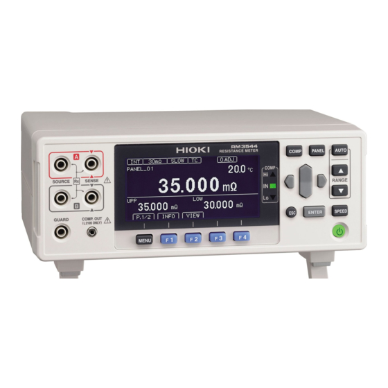
1.2 Names and Functions of Parts 1.2 Names and Functions of Parts Front Panel Viewing Measured Viewing Comparator Results Values and Settings COMP indicator LEDs Indicate the judgment result of the measured value (p.60). Display Screen (Mono- chrome graphical LCD) Measured value is above upper limit Pass (meets criteria) Display of measurements and... -
Page 26: Rear Panel
1.2 Names and Functions of Parts Rear Panel Sending and Receiving Switching between NPN and PNP Data via USB EXT I/O NPN/PNP switch USB jack Left : Current sink (NPN) Connect to a computer (p.123). Right : Current source (PNP) Connecting the Power Cord Power Inlet... -
Page 27: Measurement Process
1.3 Measurement Process 1.3 Measurement Process Front Panel Rear Panel Connect the external interface Install this instrument (p. 5) (RM3544-01; as necessary) Using the printer (p.137) • Using the USB or RS-232C inter- Connect the power • cord (p.25) face (p.121) Using the EXT I/O (p.89) - Page 28 1.3 Measurement Process *1 About zero-adjustment Perform zero-adjustment in the following circumstances: The measured value is not cleared due to thermal EMF or other factors. • → The measured value will be adjusted to zero. (Accuracy is not affected by whether or not the zero adjustment is performed.) Four-terminal connection (called Kelvin connection) is difficult.
-
Page 29: Screen Organization And Operation Overview
1.4 Screen Organization and Operation Overview 1.4 Screen Organization and Operation Overview The instrument’s screen interface consists of a Measurement screen and various Settings screens. The screen examples in this guide appear reversed (black on white) for best visibility on the printed page. - Page 30 (3) Panel Save/Load screen Select a panel number. Perform action with an F key. (4) Settings screen Move to the [MEAS], [SYS], [I/O], or [IF] tab. ([I/O] and [IF] tabs: RM3544-01 only. Not shown on RM3544.) Move among Select a settings. setting.
- Page 31 JUDGE/BCD MODE EXT I/O output mode (p.116) EXT I/O TEST Test EXT I/O (p.117) Communication INTERFACE Configure interface settings (p.123) Interface SPEED Settings screen DATA OUT Communications (p.121) (IF) CMD MONITOR PRINT INTRVL Printing (p.137) PRINT COLUMN *1 RM3544-01 only.
- Page 32 1.4 Screen Organization and Operation Overview...
-
Page 33: Chapter 2 Measurement Preparations
2.1 Connecting the Power Cord Measurement Chapter 2 Preparations Be sure to read the "Operating Precautions" (p.5) before installing and connecting this instrument. Refer to "Appendix 14 Rack Mounting" (p. A28) for rack mounting. 2.1 Connecting the Power Cord Turn off the power before disconnecting the power cord. Rear Panel Power inlet Confirm that the instrument's Main power... -
Page 34: Connecting Measurement Leads
2.2 Connecting Measurement Leads 2.2 Connecting Measurement Leads Connect the included or optional Hioki measurement leads to the measurement terminals. Before connecting the measurement leads, read "Operating Precautions" (p.5) carefully. Refer to "Options" (p.2) for details. We recommend using optional Hioki measurement leads. -
Page 35: Connecting Z2001 Temperature Sensor (When Using The Tc)
2.3 Connecting Z2001 Temperature Sensor (When using the TC) 2.3 Connecting Z2001 Temperature Sensor (When using the TC) Before connecting the temperature sensor, read "Operating Precautions" (p.5) carefully. Connection Methods Connecting the Z2001 Temperature Sensor Rear Panel TEMP.SENSOR jack Confirm that the instrument's Main power switch (rear panel) is OFF( Plug the Z2001 Temperature Sensor into the TEMP.SENSOR jack on the rear... -
Page 36: Turning The Power On And Off
2.4 Turning the Power On and Off 2.4 Turning the Power On and Off Turning On the Instrument with the Main Power Switch Turn on ( ) the main power switch on the rear of the instrument. If the main power switch was turned off while the instrument was not in the standby state, the standby state will be automatically canceled when the main power switch is turned on. -
Page 37: Placing The Instrument In The Standby State
2.4 Turning the Power On and Off After the standby state is canceled, a self-test (instrument diagnostic routine) is per- formed. During the self-test, the following information is displayed while the hardware is verified. Self-test The following information is displayed during self-testing: •... -
Page 38: Pre-Operation Inspection
Before using the instrument for the first time, verify that it operates normally to ensure that no damage occurred during storage or shipping. If you find any dam- age, contact your authorized Hioki distributor or reseller. Peripheral Device Inspection Metal Exposed... -
Page 39: Chapter 3 Basic Measurements
Basic Measurements Chapter 3 Before making measurements, read "Operating Precautions" (p. 12) carefully. This chapter explains basic operating procedures for the instrument. "3.1 Selecting the Measurement Range" (p.32) "3.2 Setting the Measurement Speed" (p.33) "3.3 Connecting Measurement Leads to the Measurement Target" (p.34) "3.4 Checking Measured Values"... -
Page 40: Selecting The Measurement Range
3.1 Selecting the Measurement Range 3.1 Selecting the Measurement Range The measurement range can be set as follows. Auto-ranging (the AUTO range) can also be selected. Manual Range Setting Select the range to use. (AUTO off) The decimal point location and unit indicator change with each key press. -
Page 41: Setting The Measurement Speed
3.2 Setting the Measurement Speed 3.2 Setting the Measurement Speed The measurement speed can be set to FAST, MED (medium), or SLOW. The MED (medium) and SLOW settings offer increased measurement precision compared to the FAST setting as well as greater resistance to the effects of the external environment. If the setup is excessively susceptible to the effects of the external environment, shield the measurement target and measurement leads adequately and twist the cables together. -
Page 42: Connecting Measurement Leads To The Measurement Target
3.3 Connecting Measurement Leads to the Measurement Target 3.3 Connecting Measurement Leads to the Mea- surement Target Before making measurements, read "Operating Precautions" (p.5) carefully. Example with L2101 Example with L2102 (Place leads in contact with target.) Example with L2104 SOURCE A SENSE A SENSE B... -
Page 43: Checking Measured Values
3.4 Checking Measured Values 3.4 Checking Measured Values The resistance value will be displayed. If the display does not indicate the mea- • sured value, see "Confirming Measure- ment Faults" (p. 38). To convert the value into a parameter • other than resistance, see below. - Page 44 3.4 Checking Measured Values Example displays Display of pre-calculation measured values varies with the settings. (No display) (Temperature display) (Value before TC calculation (Value before scaling calculation : With TC ON) : With scaling ON) Rt: Resistance measured value R: Resistance measured value before TC calculation before scaling (Value before REF% calculation...
- Page 45 3.4 Checking Measured Values Displaying a list of measurement conditions and settings Display the measurement conditions. Switch the function menu to P.1/2. [INFO] Display measurement conditions. Check the measurement conditions. If the interface type has been set to "printer," you can print settings with Return to the Measurement screen.
-
Page 46: Confirming Measurement Faults
3.4 Checking Measured Values Confirming Measurement Faults When a measurement is not performed correctly, a measurement fault indicator appears and a ERR signal of the EXT I/O is output (no ERR signal is output for over-range or unmeasured events). Operation when a current fault occurs can be changed with the set- tings. - Page 47 3.4 Checking Measured Values *1 Over-range Detection Function Examples of Over-range Faults Over-range Detection Measurement Example The measured value is outside of Attempting to measure 40 mΩ with the 30 mΩ range selected the measurement range. The relative tolerance (%) display Measuring 500 Ω...
- Page 48 3.4 Checking Measured Values Setting the measurement method for an open target (current fault mode setting) This section describes how to configure instrument operation when current fault output is detected. When set to current fault, a break in the measurement target wiring is determined to be an error, and no comparator judgment is made.
-
Page 49: Holding Measured Values
3.4 Checking Measured Values Holding Measured Values The auto-hold function provides a convenient way to check measured values. Once the measured value stabilizes, the beeper will sound, and the value will be automatically held. Open the Settings Screen. Switch the function menu to P.2/2. - Page 50 3.4 Checking Measured Values...
-
Page 51: Chapter 4 Customizing Mea- Surement Conditions
Customizing Measurement Chapter 4 Conditions Before making measurements, read "Operating Precautions" (p. 12) carefully. This chapter explains functionality employed to make more advanced, more accurate mea- surements. "4.1 Zero Adjustment" (p. 44) "4.2 Stabilizing Measured Values (Averaging Function)" (p. 50) "4.3 Correcting for the Effects of Temperature (Temperature Correction (TC))"... -
Page 52: Zero Adjustment
4.1 Zero Adjustment 4.1 Zero Adjustment Perform zero-adjustment in the following circumstances: The measured value is not cleared due to thermal EMF or other factors. • → The measured value will be adjusted to zero. (Accuracy is not affected by whether or not the zero adjustment is performed.) Four-terminal connection (called Kelvin connection) is difficult. - Page 53 4.1 Zero Adjustment Performing zero-adjustment Short the measurement leads together. L2101 Bring the "V" marks together at the same position. SENSE SENSE SOURCE SOURCE Correct Black SOURCE SENSE SENSE SOURCE Incorrect Black SENSE A SENSE B SOURCE A SOURCE B Connection Connection L2102, L2103 (options)
- Page 54 4.1 Zero Adjustment Verify that the measured value is within ±3%f.s. If the zero-adjustment range is set to NORMAL (-3%f.s. to 50%f.s.), zero-adjustment can be performed when the measured value is 50%f.s. or less in each range, but a warning will be issued when it is greater than 3%f.s.
- Page 55 4.1 Zero Adjustment Zero Adjustment Faults If zero adjustment fails, the following error message appears. Before attempting zero adjustment again, confirm the following: Verify that the measured value is within each range (NORMAL: -3%f.s. to 50%f.s., • TIGHT: -3%f.s. to 3%f.s.). When using measurement leads that you made, reduce the wiring resistance.
- Page 56 4.1 Zero Adjustment Select the zero-adjustment range setting function to be TIGHT. Selection Range: -3%f.s. to 3%f.s. Range: -3%f.s. to 50%f.s. (default) Return to the Measurement screen. Return to the Measurement screen. The changed setting will be applied to the zero-adjustment that will be performed after the setting is changed.
- Page 57 4.1 Zero Adjustment Select 0 ADJUST. Selection Cancel zero-adjustment. A confirmation message will be displayed. Confirm and return to the Mea- surement screen. Clear zero-adjustment and return Settings screen. Cancel the operation and return previous screen. Return to the Measurement screen. Return to the Measurement screen.
-
Page 58: Stabilizing Measured Values (Averaging Function)
4.2 Stabilizing Measured Values (Averaging Function) 4.2 Stabilizing Measured Values (Averaging Function) The averaging function averages multiple measured values and displays the results. It can be used to reduce variation in measured values. For internal trigger measurement (Free-Run), a moving average is calculated. For external trigger measurement (and command operation) (Non-Free-Run), a :READ? - Page 59 4.2 Stabilizing Measured Values (Averaging Function) Set the number of averaging iterations. Move the cursor to the setting you wish to configure. Make the value editable with the key. Move among Change digits. values. Move the cursor to the digit you wish to set with the left and right cursor keys.
-
Page 60: Correcting For The Effects Of Temperature (Temperature Correction (Tc))
4.3 Correcting for the Effects of Temperature (Temperature Correction (TC)) 4.3 Correcting for the Effects of Temperature (Temperature Correction (TC)) Temperature correction converts resistance values to resistance values at standard tem- perature and displays the result. For more information about the principle of temperature correction, see "Appendix 4 Tem- perature Correction (TC) Function"... - Page 61 4.3 Correcting for the Effects of Temperature (Temperature Correction (TC)) Set the reference temperature and temperature coefficient. (Set the reference temperature and temperature coefficient by following steps 1 through 3 for each.) Move the cursor to the setting you wish to configure. Make the value editable with the key.
-
Page 62: Correcting Measured Values And Displaying Physical Properties Other Than Resistance Values (Scaling Function)
4.4 Correcting Measured Values and Displaying Physical Properties Other than Resistance 4.4 Correcting Measured Values and Displaying Physical Properties Other than Resistance Values (Scaling Function) This function applies a correction to measured values. It can be used to cancel the effects of the probing position or differences between measuring instruments, or to apply a user- specified offset as an alternative to zero-adjustment. - Page 63 4.4 Correcting Measured Values and Displaying Physical Properties Other than Resistance Open the Measurement Settings Screen. Move cursor [MEAS] tab with the left and right cursor keys. Enable the scaling function. Selection Enables the scaling func- tion Disables the scaling func- tion (default) (go to step 8) Set the gain coefficient.
- Page 64 4.4 Correcting Measured Values and Displaying Physical Properties Other than Resistance Set the offset. Move the cursor to the setting you wish to configure. Make the value editable with the key. Move among Change digits. values. Move the cursor to the digit you wish to set with the left and right cursor keys.
- Page 65 4.4 Correcting Measured Values and Displaying Physical Properties Other than Resistance Edit the unit as desired. Make the value editable with the key. Move among Change digits. values. Move the cursor to the digit you wish to set with the left and right cursor keys.
-
Page 66: Changing The Number Of Measured Value Digits
4.5 Changing the Number of Measured Value Digits 4.5 Changing the Number of Measured Value Digits Open the Settings Screen. Switch the function menu to P.2/2. The Settings screen appears. Open the Measurement Settings Screen. Move cursor [MEAS] tab with the left and right cursor keys. -
Page 67: Chapter 5 Judgment Function
Judgment Chapter 5 Function This chapter explains measured value judgments (the comparator function). The compara- tor function provides the following capabilities: Displaying information on the instrument (COMP lamp Hi/IN/Lo) • Measured value > Upper limit value Upper limit value ≥ Measured value ≥ Lower limit value Measured value <... -
Page 68: Judging Measured Values (Comparator Function)
5.1 Judging Measured Values (Comparator Function) 5.1 Judging Measured Values (Comparator Function) The comparator judgment mode can be set as one of the following: Select the ABS (absolute values) judgment mode Decide whether a measured val- ue is between specified upper example Upper and lower threshold values (ab-... -
Page 69: Enabling And Disabling The Comparator Function
5.1 Judging Measured Values (Comparator Function) Enabling and Disabling the Comparator Function The comparator function is disabled by default. When the function is disabled, comparator settings are ignored. Open the Comparator Settings screen. The Comparator Settings screen appears. Enable or disable the comparator function. Switch the comparator function ON or OFF. -
Page 70: Decide According To Upper/Lower Thresholds (Abs Mode)
5.1 Judging Measured Values (Comparator Function) Decide According to Upper/Lower Thresholds (ABS Mode) Setting example: Upper threshold 150 mΩ, lower threshold 50 mΩ To abort the setting process, press . Settings are abandoned and the display returns to the pre- vious screen. - Page 71 5.1 Judging Measured Values (Comparator Function) Set the negative tolerance in the same way. Accept the settings and return to the Measurement screen.
-
Page 72: Decide According To Reference Value And Tolerance (Ref% Mode)
5.1 Judging Measured Values (Comparator Function) Decide According to Reference Value and Tolerance (REF% Mode) When REF% mode is enabled, the measured value will be displayed as an absolute value (%). Measured Value Relative Value = × 100 [%] Display range: -999.99% to +999.99% Reference (tolerance) Value... - Page 73 5.1 Judging Measured Values (Comparator Function) Set the allowable range (upper and lower limit values). Move among Change digits. values. Move the cursor to the digit you wish to set with the left and right cursor keys. Change the value with the up and down cursor keys.
-
Page 74: Delaying The Judge Timing
5.1 Judging Measured Values (Comparator Function) Delaying the judge timing The judge timing can be delayed not to decide any judgment until a measurement value becomes stable. Example when the judge delay function is set to OFF Measure- Measurement ment Fault (“- - - - -”) - Page 75 5.1 Judging Measured Values (Comparator Function) Enable the judge delay function. Selection Enables the judge delay function Disables the judge delay function (default) (go to step 5) Set the the number of unjudged measurements. Move the cursor to the setting you wish to configure.
-
Page 76: Checking Judgments Using Sound (Judgment Sound Setting Function)
5.1 Judging Measured Values (Comparator Function) Checking Judgments Using Sound (Judgment Sound Setting Function) The comparator judgment beeper can be enabled and disabled. The judgment beeper is disabled (OFF) by default. Separate judgment tones can be set for Hi, IN, and Lo judgments. Open the Settings Screen. - Page 77 5.1 Judging Measured Values (Comparator Function) Select the number of times to sound the beeper for Hi judgments. Move the cursor to the setting you wish to configure. To sound the beeper con- tinuously To set the number of beeps: Change the number of beeps.
-
Page 78: Checking Judgments With The L2105 Led Comparator Attachment (Option)
5.1 Judging Measured Values (Comparator Function) Checking Judgments with the L2105 LED Comparator Attachment (Option) By connecting the L2105 LED Comparator Attachment to the COMP.OUT jack, you can check judgment results easily at a distance from the instrument. The indicator will turn green for IN judgments and red for Hi and Lo judgments. -
Page 79: Chapter 6 Saving And Loading Panels (Saving And Loading Measure- Ment Conditions)
Saving and Loading Panels Chapter 6 (Saving and Loading Measurement Conditions) Current measurement conditions can be saved and loaded using the panel load function from the key operations, communications commands, or EXT-I/O. The instrument can save up to 10 sets of measurement conditions. Saved conditions are retained even when the instrument is turned off. -
Page 80: Saving Measurement Conditions (Panel Save Function)
6.1 Saving Measurement Conditions (Panel Save Function) 6.1 Saving Measurement Conditions (Panel Save Function) Open the Panel List Screen. The Panel List Screen appears. Save the measurement conditions. Selection Save the conditions. Enter the panel name. (If you enter the number of a previously saved panel, a warning message will be displayed.) Move Change... -
Page 81: Loading Measurement Conditions (Panel Load Function)
6.2 Loading Measurement Conditions (Panel Load Function) 6.2 Loading Measurement Conditions (Panel Load Function) Loads the measurement settings saved by the Panel Save function. By default, loading a panel causes zero-adjustment values to be loaded. If you do not wish to load zero-adjustment values, see "Preventing Loading of Zero-adjustment Values"(p.74). -
Page 82: Preventing Loading Of Zero-Adjustment Values
6.2 Loading Measurement Conditions (Panel Load Function) Panels can also be loaded with the EXT I/O LOAD0 to LOAD3 control and communica- • tions commands. See: "Chapter 8 External Control (EXT I/O)"; "Input Signals" (p. 93) For more information about commands, see the included application disc. If measurement conditions are changed after being loaded, the panel name will no longer •... -
Page 83: Changing Panel Names
6.3 Changing Panel Names 6.3 Changing Panel Names Open the Panel List Screen. The Panel List Screen appears. Select a panel number. Selection Edit the panel name. Edit the panel name. Move Change among characters. characters. Move the cursor to the character you wish to set with the left and right cursor keys. -
Page 84: Deleting Panel Data
6.4 Deleting Panel Data 6.4 Deleting Panel Data Open the Panel List Screen. The Panel List Screen appears. Select a panel number. Selection Delete the panel. Verify that the confirmation message is shown and return to the Measurement screen. Delete the panel and switch to the previous screen (you can also do this with the key). -
Page 85: Chapter 7 System Settings
Chapter 7 System Settings This chapter describes system settings. "7.1 Disabling and Enabling Key Operations" (p. 78) "7.2 Power Line Frequency Manual Setting" (p. 80) "7.3 Enabling or Disabling the Key Beeper" (p. 82) "7.4 Adjusting Screen Contrast" (p. 83) "7.5 Adjusting the Backlight"... -
Page 86: Disabling And Enabling Key Operations
7.1 Disabling and Enabling Key Operations 7.1 Disabling and Enabling Key Operations Disabling Key Operations (Key-Lock Function) Activate the key-lock function to disable the instrument’s front panel key operations. Three key-lock levels are available to suit specific purposes. Disabling All Except Comparator Settings Only basic settings RANGE ▲▼... -
Page 87: Re-Enabling Key Operations (Key-Lock Cancel)
7.1 Disabling and Enabling Key Operations Enable or disable key operations. Disable all except key-lock cancel and return to the Measurement screen. Disable all except key-lock cancel and basic settings change and return to the Measurement screen. Return to the Measurement screen. -
Page 88: Power Line Frequency Manual Setting
7.2 Power Line Frequency Manual Setting 7.2 Power Line Frequency Manual Setting With the default setting (AUTO), the instrument attempts to automatically detect the line fre- quency, but manual setting is also available. Unless the line frequency is set correctly, measured values may be unstable. •... -
Page 89: 7.2 Power Line Frequency Manual Setting
7.2 Power Line Frequency Manual Setting Select the line frequency being used. Selection Automatically detect local line frequency (default) When the line frequency is 50 Hz When the line frequency is 60 Hz Return to the Measurement screen. Return to the Measurement screen. -
Page 90: Enabling Or Disabling The Key Beeper
7.3 Enabling or Disabling the Key Beeper 7.3 Enabling or Disabling the Key Beeper The key beeper sound can be enabled and disabled. The key beeper is enabled (ON) by default. Open the Settings Screen. Switch the function menu to P.2/2. The Settings screen appears. -
Page 91: Adjusting Screen Contrast
7.4 Adjusting Screen Contrast 7.4 Adjusting Screen Contrast The screen may become hard to see when ambient temperature changes. In this case, adjust the contrast. Open the Settings Screen. Switch the function menu to P.2/2. The Settings screen appears. Open the System Setting Screen. Move the cursor to the [SYS] tab with the left and right cur- sor keys. -
Page 92: Adjusting The Backlight
7.5 Adjusting the Backlight 7.5 Adjusting the Backlight Adjust backlight brightness to suit ambient illumination. When external (EXT) triggering is selected, backlight brightness is automatically reduced • after non-operation for one minute. Be aware that the display may be hard to see when brightness is set too low (near 0%). •... -
Page 93: Initializing (Reset)
7.6 Initializing (Reset) 7.6 Initializing (Reset) Two reset functions are available. For more information about communications commands, see the included application disc. Reset: Returns measurement conditions (except the panel data) to factory defaults. The instrument can be reset by three methods. Reset from the System setting screen •... - Page 94 7.6 Initializing (Reset) Select RESET. Selection Perform a reset. Perform a system reset. Select whether to initialize the instrument. Execute Cancel the operation The Measurement screen is displayed when system reset finishes.
-
Page 95: Initializing (Reset)
(p.110) (I/O) TRIG/PRINT FILT (p.112) EOM MODE HOLD (p.114) JUDGE/BCD MODE JUDGE (p.116) Communications INTERFACE RS232C (p.123) Interface SPEED 9600bps (p.126) Settings screen DATA OUT (p.133) (IF) CMD MONITOR (p.131) PRINT INTRVL (p.142) PRINT COLUMN 1LINE (p.141) *1 RM3544-01 only... - Page 96 7.6 Initializing (Reset)
-
Page 97: Chapter 8 External Control
External Control Chapter 8 (EXT I/O) The EXT I/O connector on the rear of the instrument supports external control by providing output of the EOM and comparator judgment signals, and accepting input of TRIG and KEY_LOCK signals. All signals are isolated from the measurement circuit and ground (I/O common pins are shared). -
Page 98: External Input/Output Connector And Signals
The NPN/PNP switch allows you to change the type of programmable controller that is sup- ported. The instrument ships with the switch set to the NPN position. See: "8.3 Internal Circuitry"(p.104) NPN/PNP switch setting RM3544 input circuit Supports sink output. Supports source output. RM3544 output circuit Non-polar Non-polar... -
Page 99: Connector Type And Signal Pinouts
8.1 External Input/Output Connector and Signals Connector Type and Signal Pinouts Before connecting a connector, see "Before Connecting EXT I/O" (p. 11). Use of EXT I/O enables the following control functionality: Measurement start (TRIG) → Measurement end (EOM, INDEX) • →... - Page 100 8.1 External Input/Output Connector and Signals Pin Signal name I/O Function Logic Pin Signal name I/O Function Logic LOAD3 Panel load Level 24 (Reserved) (Reserved) (Reserved) Printing of PRINT measured values (Reserved) Edge General-pur- pose input Isolated power Isolated appli- ISO_5V supply +5 V ISO_COM...
-
Page 101: Signal Descriptions
8.1 External Input/Output Connector and Signals Signal Descriptions (1) Isolated power supply NPN/PNP switch setting Signal name Isolated power Isolated power ISO_5V supply +5 V supply -5 V 9, 27 ISO_COM Isolated common signal ground (2) Input Signals TRIG p.110 The TRIG signal operates at either the ON or OFF edge. - Page 102 8.1 External Input/Output Connector and Signals (3) Output Signals p.114 This signal indicates the end of measurement and zero-adjustment. At this point in time, the comparator judgment results and the ERR and BCD signals have been finalized. INDEX This signal indicates that A/D conversion in the measurement circuit is fin- ished.
- Page 103 8.1 External Input/Output Connector and Signals JUDGE mode and BCD mode Output signals operate under either JUDGE mode or BCD mode. In BCD mode, signals are used for both the upper and lower digits (and range information). See: "Switching Output Modes (JUDGE Mode/ BCD Mode)" (p. 116) Pin functions in JUDGE mode Function Function...
- Page 104 8.1 External Input/Output Connector and Signals (4) Signal correspondence chart LOAD0 to LOAD3 LOAD3 LOAD2 LOAD1 LOAD0 Panel number No change No change No change No change No change No change RNG_OUT0 to RNG_OUT3 RNG_OUT3 RNG_OUT2 RNG_OUT1 RNG_OUT0 Range 30 mΩ 300 mΩ...
-
Page 105: Timing Chart
8.2 Timing Chart Timing Chart Each signal level indicates the ON/OFF state of a contact. When using the current source (PNP) setting, the level is the same as the EXT I/O pin voltage level. When using the cur- rent sink (NPN) setting, the high and low voltage levels are reversed. From Start of Measurement to Acquisition of Judgment Results (1) External trigger [EXT] setting (EOM output hold) TRIG... - Page 106 8.2 Timing Chart (2) External trigger [EXT] setting (EOM output pulse) The EOM signal turns ON at the end of measurement and then reverts to the OFF state once the time (t5) that has been set as the EOM pulse width elapses. TRIG Measurement INDEX...
- Page 107 8.2 Timing Chart Timing Chart Interval Descriptions Interval Description Duration Remarks Trigger Pulse 0.1 ms or more ON/ OFF-edge selectable Asserted (ON) Trigger Pulse 1 ms or more De-asserted (OFF) Measurement 1 ms, max start time Acquisition process- FAST (50 Hz) : 20 ms Reference value ing time FAST (60 Hz) : 17 ms...
-
Page 108: Panel Load Timing
8.2 Timing Chart Panel Load Timing LOAD0 to LOAD3 Panel 1 Panel 2 Approx. , max Approx. 0.5 s 10 ms State Panel 1 Load processing Panel 2 BCD Signal Timing BCDm_n signal transition time based on the BCD_LOW signal BCD_LOW Upper (OFF) Lower (ON) -
Page 109: Output Signal State At Power-On
8.2 Timing Chart Output Signal State at Power-On When transitioning from the Startup screen to the Measurement screen after turning on the instrument’s power, the EOM and INDEX signals will turn ON. When using pulse EOM output, the signals will remain OFF. Power-On Initial Screen Measurement Screen... -
Page 110: Acquisition Process When Using An External Trigger
8.2 Timing Chart Acquisition Process When Using an External Trigger This section describes the process from measurement start to acquisition of judgment results or measured values when using an external trigger. The instrument outputs the EOM signal immediately once the judgment result (HI, IN, LO, ERR) has been finalized. - Page 111 8.2 Timing Chart Measured value (BCD) acquisition processing when using an external trigger For BCD output, the upper and lower digits must be acquired separately. The upper and lower digits can be acquired in any order. In the following example, the upper digits are acquired first.
-
Page 112: Internal Circuitry
8.3 Internal Circuitry 8.3 Internal Circuitry NPN Setting Do not connect external power to pin 8. RM3544, RM3544-01 PLC, etc. Output Common Internally isolated power PLC, etc. Input Zener Voltage 30 V Common Internally Isolated Common Signal Ground * Isolate from the instrument protective ground. - Page 113 8.3 Internal Circuitry PNP Setting Do not connect external power to pin 8. RM3544, RM3544-01 PLC, etc. Output Common Internally isolated power PLC, etc. Input Zener Voltage 30 V Common Internally Isolated Common Signal Ground * Isolate from the instrument protective ground.
-
Page 114: Electrical Specifications
8.3 Internal Circuitry Electrical Specifications Input type Optocoupler-isolated, non-voltage contact inputs Input Signals (Current sink/source output compatible) Input asserted (ON) Residual voltage: 1 V (Input asserted (ON) current: 4 mA typ) Open (shutoff current: 100 μA or less) Input de-asserted (OFF) Output type Optocoupler-isolated, open drain output (non-polar) Output Signals... -
Page 115: Connection Examples
8.3 Internal Circuitry Connection Examples Input Circuit Connection Examples RM3544 RM3544 Input Input Switch Connections Relay Connections RM3544 RM3544 Input Input Output Output Common Common PLC Output (NPN Output) Connections PLC Output (PNP Output) Connections Output Circuit Connection Examples RM3544... -
Page 116: External I/O Settings
8.4 External I/O Settings 8.4 External I/O Settings The following external I/O settings are provided: Input settings Set the measurement start conditions (trigger source).(p.108) • Set the TRIG signal logic.(p.110) • Eliminate TRIG/PRINT signal chatter (filter function).(p.112) • Output settings Set the EOM signal.(p.114) •... - Page 117 8.4 External I/O Settings Switching the trigger source Open the Settings Screen. Switch the function menu to P.2/2. The Settings screen appears. Open the EXT I/O Setting Screen. Move the cursor to the [I/O] tab with the left and right cur- sor keys.
-
Page 118: Setting The Trig Signal Logic
8.4 External I/O Settings Setting the TRIG Signal Logic Select the ON or OFF edge as the logic at which the TRIG signal is enabled. When using the OFF edge, measurement times will be increased by approximately 1.0 ms. Open the Settings Screen. Switch the function menu to P.2/2. - Page 119 8.4 External I/O Settings ON edge and OFF edge operation ON edge • TRIG Measurement Measurement processing OFF edge • TRIG Measurement Measurement processing Measurement times will be 1.0 ms longer when using the OFF edge than when using the ON edge.
-
Page 120: Eliminating Trig/Print Signal Chatter (Filter Function)
8.4 External I/O Settings Eliminating TRIG/PRINT Signal Chatter (Filter Function) The filter function, which eliminates chatter, is useful when connecting a foot switch or sim- ilar device to the TRIG/PRINT signal. Open the Settings Screen. Switch the function menu to P.2/2. The Settings screen appears. - Page 121 8.4 External I/O Settings Set the response time. Move the cursor to the setting you wish to configure. Make the value editable with the key. Move among Change digits. values. Move the cursor to the digit you wish to set with the left and right cursor keys.
-
Page 122: Setting Eom Signal
8.4 External I/O Settings Setting EOM Signal You can select whether to hold EOM signal output until the next trigger is input or output a user-specified pulse width. When using the internal trigger [INT], the EOM pulse width is fixed at 5 ms, regardless of the settings. - Page 123 8.4 External I/O Settings (When PULSE is selected) Select the pulse width. Move the cursor to the setting you wish to configure. Make the value editable with the key. Move among Change digits. values. Move the cursor to the digit you wish to set with the left and right cursor keys.
-
Page 124: Switching Output Modes (Judge Mode/ Bcd Mode)
8.4 External I/O Settings Switching Output Modes (JUDGE Mode/ BCD Mode) Open the Settings Screen. Switch the function menu to P.2/2. The Settings screen appears. Open the EXT I/O Setting Screen. Move the cursor to the [I/O] tab with the left and right cur- sor keys. -
Page 125: Checking External Control
8.5 Checking External Control 8.5 Checking External Control Performing an I/O Test (EXT I/O Test Function) In addition to switching output signals ON and OFF manually, you can view the input signal state on the screen. Open the Settings Screen. Switch the function menu to P.2/2. - Page 126 8.5 Checking External Control Perform the EXT I/O test. Output signals Allows you to perform signal oper- ations. (ON: Reverse video; OFF: Normal display) : Select signal. : Turn signal ON. : Turn signal OFF. Input signals Displays the signal state. (ON: Reverse video;...
-
Page 127: Supplied Connector Assembly
8.6 Supplied Connector Assembly 8.6 Supplied Connector Assembly The EXT I/O connector and shell are supplied with the instrument. Assemble as shown below. Use shielded cables to connect a PLC to the EXT I/O connector. Using non-shielded con- • ductors may result in system errors from electrical noise. Connect the shield to the ISO_COM pin of the EXT I/O connector. - Page 128 8.6 Supplied Connector Assembly...
-
Page 129: Chapter 9 Communications
Use the sample application.* Acquiring Data" (p.130) ment) (Data Output Function)" (p.133) * The sample application can be downloaded from the Hioki website (http://www.hioki.com). Communications times There may be a display processing lag depending on the frequency and nature of any •... -
Page 130: Specifications
9.1 Overview and Features Specifications You must select one communications interface for use. Communications control using dif- ferent interfaces cannot be performed simultaneously. USB Specifications Connector Series B receptacle Electrical specification USB2.0 (Full Speed) Class CDC Class, HID Class Message terminator Receiving: CR+LF, CR (delimiter) Transmitting: CR+LF... -
Page 131: Preparations Before Use (Connections And Settings)
9.2 Preparations before Use (Connections and Settings) 9.2 Preparations before Use (Connections and Settings) Using the USB Interface 1. Configuring USB Interface Communications Make these instrument settings. Open the Settings Screen. Switch the function menu to P.2/2. The Settings screen appears. - Page 132 9.2 Preparations before Use (Connections and Settings) Select the USB connection mode. Move the cursor to the setting you wish to configure. USB keyboard mode COM mode (default) Return to the Measurement screen. Return to the Measure- ment screen, and enable the communications inter- face.
- Page 133 USB driver. The following procedure need not be fol- lowed if the driver has already been installed, for example in the course of using another Hioki product. The USB driver can be found on the included application disc or down- loaded from the Hioki website (http://www.hioki.com).
-
Page 134: Using The Rs-232C Interface
9.2 Preparations before Use (Connections and Settings) Using the RS-232C Interface 1. Configuring RS-232C Interface Communications Make these instrument settings. Open the Settings Screen. Switch the function menu to P.2/2. The Settings screen appears. Open the Communications Interface Settings Screen. Move the cursor to the [IF] tab with the left and right cursor keys. - Page 135 9.2 Preparations before Use (Connections and Settings) Select the interface transfer rate (baud rate). Selection 9600 (bps) (default) 19200 (bps) 38400 (bps) 115200 (bps) Return to the Measurement screen. Return to the Measure- ment screen, and enable the communications inter- face.
- Page 136 9.2 Preparations before Use (Connections and Settings) 2. Connect the RS-232C cable. Connect the RS-232C cable to the RS-232C connector. When connecting the cable, be sure to tighten the connector in place with screws. 1 2 3 4 5 Male 9-pin D-sub #4-40 attaching screws 6 7 8 9 To connect the instrument to a controller (DTE), use a cross-...
- Page 137 PC/AT-end Pin No. Pin No. Recommended cable: HIOKI Model 9637 RS-232C Cable (1.8 m) Connecting a controller with a 25-pin D-sub female port Use a crossover cable with a female 9-pin D-sub and a male 25-pin D-sub connector. As the figure shows, RTS and CTS pins are shorted together and crossed to DCD in the other connector.
-
Page 138: Controlling The Instrument With Commands And Acquiring Data
9.3 Controlling the Instrument with Commands and Acquiring Data 9.3 Controlling the Instrument with Commands and Acquiring Data For more information about communications commands and query notation (from the com- munications message reference), see the Communications Command Instruction Manual on the included application disc. When creating programs, the communications monitor function can be used to display commands and their associated responses on the Mea- surement screen. -
Page 139: Displaying Communications Commands (Communications Monitor Function)
9.3 Controlling the Instrument with Commands and Acquiring Data Displaying Communications Commands (Communications Monitor Function) The communications monitor function can be used to display communications commands and query responses on the instrument’s screen. Open the Settings Screen. Switch the function menu to P.2/2. - Page 140 9.3 Controlling the Instrument with Commands and Acquiring Data Command and queries will be displayed on the bottom of the Measurement screen. Messages displayed in the communications monitor and their meanings If an error occurs during command execution, the following information will be displayed: Command error (improper command, improper argument format, etc.) •...
-
Page 141: Auto-Exporting Measured Values (At End Of Measurement) (Data Output Function)
9.4 Auto-Exporting Measured Values (at End of Measurement) (Data Output Function) 9.4 Auto-Exporting Measured Values (at End of Measurement) (Data Output Function) Once measurement completes, the instrument can send measured values automatically as data to a computer via its UBS or RS-232C interface. There are two methods for sending data. -
Page 142: 9.4 Auto-Exporting Measured Values (At End
9.4 Auto-Exporting Measured Values (at End of Measurement) (Data Output Function) Open the Settings Screen. Switch the function menu to P.2/2. The Settings screen appears. Open the Communications Interface Settings Screen. Move the cursor to the [IF] tab with the left and right cursor keys. -
Page 143: 9.4 Auto-Exporting Measured Values (At End
9.4 Auto-Exporting Measured Values (at End of Measurement) (Data Output Function) Select the auto-exporting condition (depending on a judgment). Selection Select judgment con- dition Exports measurement values re- gardless of judgments (default) Exports measurement values only with Hi judgments Exports measurement values only with IN judgments... -
Page 144: 9.4 Auto-Exporting Measured Values (At End
9.4 Auto-Exporting Measured Values (at End of Measurement) (Data Output Function) -
Page 145: Connecting The Printer To The Instrument
10.1 Connecting the Printer to the Instrument Printing Chapter 10 (Using an RS-232C Printer) Connecting Printing (p.140) Make instrument Make printer the printer to Measured values and • settings (p.139) settings the instrument comparator judgments List of measurement • conditions and set- tings 10.1 Connecting the Printer to the Instrument Before connecting a printer, read "Operating Precautions"... - Page 146 AC Adapter RS-232C Cable Connector Pinouts 1 2 3 4 5 13 ....... 1 25 ....... 14 6 7 8 9 RM3544 (9-pin) Connector Printer (25-pin) Connector (Example) Signal Signal Circuit name Circuit name Name Name Receive Data...
- Page 147 10.1 Connecting the Printer to the Instrument Instrument Settings Open the Settings Screen. Switch the function menu to P.2/2. The Settings screen appears. Open the Communications Interface Settings Screen. Move the cursor to the [IF] tab with the left and right cursor keys.
-
Page 148: Printing
10.2 Printing 10.2 Printing Before Printing Verify that the instrument settings (p.139) are correct. Printing Measured Values and Comparator Judgments Printing by key operation Pressing on Measurement [PRINT] screen P.1/2 causes the current mea- sured value to be printed. When the is used as the trigger, one mea- surement will be performed and the results printed. - Page 149 10.2 Printing Changing the number of columns printed per row Normally a row consists of one column, but you can also print three columns per row. When printing three columns per row, the temperature and interval time are not printed. Open the Settings Screen.
- Page 150 10.2 Printing Interval printing You can automatically print measured values at a fixed time interval. Open the Settings Screen. Switch the function menu to P.2/2. The Settings screen appears. Open the Communications Interface Settings Screen. Move the cursor to the [IF] tab with the left and right cursor keys.
- Page 151 10.2 Printing Set the interval. Move the cursor to the setting you wish to configure. Make the value editable with the key. Move among Change digits. values. Move the cursor to the digit you wish to set with the left and right cursor keys.
- Page 152 10.999 Ohm IN , 11.998 Ohm Hi , 11.998 Ohm Hi Interval printing 00:00:00 21.597mOhm 00:00:01 21.600mOhm 00:00:02 21.605mOhm 00:00:03 21.608mOhm 00:00:04 21.612mOhm 00:00:05 21.615mOhm List of measurement conditions and settings MODEL RM3544-01 000000000 RANGE 300Ohm(1mA) SPEED SLOW A.HOLD OFF 0 ADJ SCALE LINE AUTO(60Hz) TRIG PRINT...
-
Page 153: Chapter 11 Specifications
Chapter 11 Specifications Chapter 11 Specifications 11.1 Instrument Specifications Measurement Ranges 0.000 mΩ (30 mΩ range) to 3.500 0 MΩ (3 MΩ range) (in 9 ranges) Measurement Method Measurement signal Constant current Measurement method Four-terminal Measurement terminals Banana terminals SOURCE A Current detection terminal SOURCE B Current sourcing terminal... -
Page 154: Measurement Specifications
Chapter 11 Specifications Measurement Specifications (1) Resistance Measurement Accuracy Conditions of guaranteed accuracy Temperature and hu- 23±5°C, 80%RH or less midity range for guar- anteed accuracy Period of guaranteed 1 year accuracy Temperature Add (±1/10th of measurement accuracy per °C) from 0 to 18°C and from 28 to coefficient 40°C. - Page 155 Chapter 11 Specifications (2) Temperature measurement accuracy (Thermistor sensor) Guaranteed accuracy -10.0 to 99.9°C range Display range -10.0 to 99.9°C Measurement period 2 ± 0.2 s (speed) Period of guaranteed 1 year accuracy Combined accuracy with Model Z2001 Temperature Sensor Accuracy Temperature range ±(0.55 + 0.009×|t -10|)°C...
-
Page 156: About Instrument Accuracy
Chapter 11 Specifications About Instrument Accuracy We define measurement tolerances in terms of f.s. (full scale), rdg. (reading) and dgt. (digit) values, with the following meanings. f.s. (maximum display value) This is usually the name of the maximum displayable value. For this instrument, it indicates the currently selected range. -
Page 157: Functions
Chapter 11 Specifications Functions (1) Resistance range switching function Mode AUTO/ MANUAL (fixed to MANUAL when comparator function is ON) Default setting AUTO (2) Number of measurement digits selection function Number measure- 5digits/ 4digits ment digits selection Default setting 5digits (3) Measurement Speed Setting FAST/ MED/ SLOW... - Page 158 Chapter 11 Specifications (6) Averaging function Operation A moving average is used when using the internal trigger source with continu- ous measurement on (free-run). A mean average is used when using an exter- nal trigger source or with continuous measurement off (non-free-run). Moving average Mean average −...
- Page 159 Chapter 11 Specifications (8) Scaling Function Operation Measured values are corrected with the linear function R = A × R + B : Value after scaling : Gain coefficient Setting range: 0.2000 × 10 to 1.9999 × 10 : Measured value after zero-adjustment and temperature correction : Offset Setting range: 0 to ±1 ×...
- Page 160 Chapter 11 Specifications (10)Comparator Function Operation Compares setting and measured values Setting ON/OFF (fixed range when comparator function is ON) Comparator mode REF%/ ABS Default state OFF, ABS mode Judgment Measured value > Upper limit value Upper limit value ≥ measured value ≥ Lower limit value Lower limit value >...
- Page 161 Chapter 11 Specifications (12)Comparator Beeper Setting Operation Sounds a beeper based on the comparator judgment result. Operation settings and Hi : type 1/ type 2/ type 3/ OFF tones IN : type 1/ type 2/ type 3/ OFF Lo : type 1/ type 2/ type 3/ OFF Number of beeps Hi : 1 to 5 times / continuous IN : 1 to 5 times / continuous...
-
Page 162: Interface
Chapter 11 Specifications Interface (1) Display LCD type Monochrome graphical LCD 240 × 110 Backlight White LED Brightness adjustment range: 0 to 100% (5% increments), Default setting: 80% When using EXT trigger source, brightness is automatically reduced when keys are not used. Brightness recovers upon front panel key operation. - Page 163 Chapter 11 Specifications (3) Communications interfaces Interface types RS-232C/ PRINTER/ USB Default setting RS-232C RS-232C and printer communications settings Communication Remote control, measured value output (export) contents Transfer method Asynchronous, Full duplex Transmission speed 9,600bps (default setting)/ 19,200bps/ 38,400bps/ 115,200bps Data length 8 bit Stop bit...
- Page 164 Auto-exporting depending on judgments: ALL Maintenance terminal Function Unused (maintenance use only) (4) EXT I/O (RM3544-01 only) Input Signals TRIG (IN0), KEY_LOCK, 0ADJ, PRINT (IN1), LOAD0 to LOAD3 Valid only with BCD mode output: BCD_LOW Optocoupler-isolated : no-voltage contact inputs (current sink/source output...
- Page 165 Chapter 11 Specifications TRIG/ PRINT filter function Setting ON/ OFF Response time 50 to 500 ms Default setting OFF, 50 ms Start Logic Setting Setting OFF edge/ ON edge Default setting ON edge EOM output timing setting Setting HOLD/ PULSE Pulse width...
-
Page 166: Environment And Safety Specifications
Maximum rated power 15 VA Dimensions Approx. 215W × 80H × 166D mm (8.46"W × 3.15"H × 6.54"D) Mass Approx. 0.9 kg (31.7 oz.) (RM3544) Approx. 1.0 kg (35.3 oz.) (RM3544-01) Product warranty period 1 year Accessories • Power Cord (2-line + ground) •... -
Page 167: Chapter 12 Maintenance And Service
If damage is suspected, check the "Q&A (Frequently Asked Questions)" (p.160) section before contact your authorized Hioki distributor or reseller. Transporting Use the original packing materials when transporting the instrument, if possible. -
Page 168: Troubleshooting
12.1 Troubleshooting 12.1 Troubleshooting Q&A (Frequently Asked Questions) The following tables provide information about general issues. For more information about issues related to measured values, or the instrument’s external interfaces, see the following pages. If you are unable to find information about a particular issue, please contact your distributor. 1. - Page 169 12.1 Troubleshooting Possible causes → Solutions Issue Items to check p.70 1-4 The LED Com- Instrument’s com- The attachment is not properly parator Attach- parator lamp connected. →Connect the LED Comparator ment will not turn Attachment properly COMP.OUT jack. − There is a broken connection.
- Page 170 12.1 Troubleshooting 2. Measurement issues Possible causes → Solutions Issue Items to check p.A13 2-1 Measured val- Effects of noise Susceptibility to See Appendix 7(1)(2). p.A15 ues are unstable. noise p.A16 Measurement leads Clip-type leads See Appendix 7(3). p.A19 Wiring becomes See Appendix 7(10).
- Page 171 12.1 Troubleshooting Possible causes → Solutions Issue Items to check p.44 2-2 Measured val- Zero-adjustment Zero-adjustment is not accurate. →Perform zero-adjustment again. p.35 ues differ from expected values. p.44 Values are being affected by wir- (A negative value ing resistance or thermoelectric is shown.) power due to two-terminal mea- surement.
- Page 172 12.1 Troubleshooting Possible causes → Solutions Issue Items to check p.A8 2-5 It is impossible to Measured values before zero-adjust- There is a problem with the wiring. →Repeat zero-adjustment with perform zero- ment exceed -3% to 50% of each range adjustment.
- Page 173 12.1 Troubleshooting 3. EXT I/O issues The EXT I/O test (p.117) function can be used to more easily check operation. Issue Items to check Possible causes→Solutions p.89 3-1 The instrument is The IN and OUT values displayed on The wiring is incorrect. →Check EXT I/O (p.89) again.
- Page 174 12.1 Troubleshooting Issue Items to check Possible causes→Solutions p.165 3-5 EOM is not being The measured value is not being See No. 3-2 above. output. updated. − EOM signal logic (The EOM signal turns ON when measurement completes.) p.114 EOM signal setting Pulse The pulse width is too narrow, and the EOM signal is not being read...
- Page 175 12.1 Troubleshooting Issue Items to check Possible causes→Solutions 4-2 An error is being Display Command error The command isn’t being recognized as encountered. a valid instruction. →Check the spelling of the command (space: x20H). →Do not append a question mark to commands that are not queries.
- Page 176 PLC side. Measured values can be acquired using the sample appli- Can free-running measured values cation. The sample application can be downloaded from the be acquired using a footswitch? Hioki website (http://www.hioki.com).
-
Page 177: Troubleshooting
Error Displays and Remedies The following messages are displayed when the instrument detects an error or abnormal measurement setting. If repair is necessary, contact your authorized Hioki distributor or reseller. If damage is suspected, check the "Q&A (Frequently Asked Questions)" (p.160) section •... - Page 178 (or SYSTEM RESET) The Adjustment screen is used Enter password for Enter the password for adjust- in repairs and adjustment car- INFO:040 Adjustment Mode. ment mode. ried out by HIOKI. It is not avail- able for use by end-users.
-
Page 179: Replacing The Measurement Circuit's Protective Fuse
12.2 Replacing the Measurement Circuit’s Protective Fuse 12.2 Replacing the Measurement Circuit’s Protective Fuse Replace the fuse only with one of the specified type, characteristics, • rated current, and rated voltage. Do not use fuses other than those specified (especially, do not use a fuse with higher-rated current) or do not short circuit and use the fuse holder. -
Page 180: Inspection And Repair
Replaceable Parts and Operating Lifetimes Useful life depends on the operating environment and frequency of use. Operation cannot be guaranteed beyond the following periods. For replacement parts, contact your autho- rized Hioki distributor or reseller. Part Life Electrolytic Capacitors Approx. -
Page 181: Appendix
Appendix 1 Block Diagram Appendix Appendix 1 Block Diagram Constant current (determined by the measurement range) is applied between the • SOURCE B and SOURCE A terminals while voltage is measured between the SENSE B and SENSE A terminals. The resistance value is obtained by dividing the measured volt- age (B) by the constant current flow (A). -
Page 182: Appendix 2 Four-Terminal (Voltage-Drop) Method
Consequently, measure- ment can be performed accurately without being affected by the measurement lead resis- tance or contact resistance. *RM3544 voltmeter’s input impedance: Approx. 1 GΩ (reference value) Two-Terminal Measurement Method Four-Terminal Measurement Method... -
Page 183: Appendix 3 Dc And Ac Measurement
Appendix 3 DC and AC Measurement Appendix 3 DC and AC Measurement Resistance (impedance) measurement can be performed using the DC or AC method. DC method • RM3542, RM3543, RM3544, RM3545, RM3548 resistance meters Standard digital multimeters Standard insulation resistance meters AC method •... -
Page 184: Appendix 4 Temperature Correction (Tc) Function
Appendix 4 Temperature Correction (TC) Function Appendix 4 Temperature Correction (TC) Function The temperature correction function converts the resistance values of temperature-depen- dent measurement targets such as copper wire into resistance values at a specific temper- ature (known as the standard temperature) and displays the results. Resistances R and R below are the resistance values of the measurement target (having... - Page 185 Appendix 4 Temperature Correction (TC) Function Reference _____________________________________________________ Conductive Properties of Metals and Alloys Density (x10 Temp. Coeff. Material Content [%] Conductivity (20°C) [ppm/°C] [ kg/m Annealed copper wire Cu>99.9 8.89 1.00 to 1.02 3810 to 3970 Hard-drawn copper Cu>99.9 8.89 0.96 to 0.98 3770 to 3850...
-
Page 186: Appendix 5 Effect Of Thermal Emf
Appendix 5 Effect of Thermal EMF Appendix 5 Effect of Thermal EMF ≠ Thermoelectromotive force Temperature t Temperature t (thermal EMF) is the potential Metal A difference that occurs at the This This junction of two dissimilar met- instrument instrument als, including between Metal B... - Page 187 Appendix 5 Effect of Thermal EMF 1. Increasing the detection voltage by increasing the measurement current In the above thermal EMF example, assume that the measurement current is increased from 100 mA to 1 A. The error will be reduced to 1%. 1 mΩ...
-
Page 188: Appendix 6 Zero Adjustment
Appendix 6 Zero Adjustment Appendix 6 Zero Adjustment Zero adjustment is a function which adjusts the zero point by deducting the residual value obtained during 0 Ω measurement. For this reason, zero adjustment must be performed when connection is made to 0 Ω. However, connecting a sample with no resistance is diffi- cult and therefore is not practical. - Page 189 Appendix 6 Zero Adjustment To perform zero adjustment appropriately Table 1 shows the correct and wrong connections. The resistances in the figure indicate lead resistances; there will be no problem if they are less than few Ω respectively In (a), if you connect SENSE A and SENSE B as well as SOURCE A and SOURCE B respectively, and use one path to make connection between SENSE and SOURCE, no potential difference occurs between SENSE A and SENSE B, and 0 V is input.
- Page 190 Appendix 6 Zero Adjustment To perform zero adjustment using measurement leads When you actually perform zero adjustment using measurement leads, you may unexpect- edly make the connection shown in Table 1 (b). Therefore, when performing zero adjust- ment, you need to pay sufficient attention to the connection state of each terminal. Here, L2101 Clip Type Lead is used as an example for the connection explanation.
- Page 191 Appendix 6 Zero Adjustment To perform zero adjustment using 9454 Zero Adjustment Board When performing zero adjustment, you cannot use a metal board or similar object to replace 9454 Zero Adjustment Board. 9454 Zero Adjustment Board is not just a metal board. Its structure consists of two layers of metal boards screwed at one point.
- Page 192 Table 1 (a) and perform zero adjustment. However, if a HIOKI product is used, even in AC resistance measurement, if the required resolution exceeds 100 μΩ, the same zero adjustment method used in DC resistance meter...
- Page 193 Appendix 7 Unstable Measured Values Appendix 7 Unstable Measured Values If the measured value is unstable, verify the following. (1) Effects of induced noise Power cords, fluorescent lights, solenoid valves, computer displays, and other devices emit large amounts of noise. Two sources of noise with the potential to affect resistance mea- surement are: 1.
- Page 194 Appendix 7 Unstable Measured Values When measuring a 1 mΩ resistor with 1 A, the effect measures 0.07%. Since the detection voltage can easily be increased for high-resis- tance measurement, this effect does not pose a Twisting significant problem. The influence of electromagnetic coupling can be reduced by keeping the noise generating line away from the voltage detection line and .
- Page 195 Susceptibility to Conductive Noise Figure 5. An effective approach is to monitor conductive noise with an instrument such as the Hioki 3145 Noise HiLogger and implement countermeasures as appropriate. Once the path along which the noise is traveling has been identified, the countermeasures show in Fig. 6 are effective.
- Page 196 Appendix 7 Unstable Measured Values Using separate power supply lines It is preferable to place power circuits, welders, and other equipment on a separate power supply from the instrument. Adding a common-mode filter (EMI choke) to the noise path Choose common mode filters with as high an impedance as possible and use multiple fil- ters for increased effectiveness.
- Page 197 Appendix 7 Unstable Measured Values (4) Wider/Thicker measurement targets When the measurement target is wide or thick like a board or block, or when using a current sensing 0.1mΩ resistor (shunt resistor) of less than 100 mΩ, it will 0.2mΩ be difficult to measure accurately using Pin Type Ω...
- Page 198 When measuring measurement targets with a large inductance component and a high Q value, such as large transformers or motors, measured values may be unstable. The RM3544 depends on constant current flow through the measurement target. To obtain stability in a constant-current source with a large inductance, response time is sacrificed. If you find that resistance values are scattered when measuring large transformers or motors, please consider the above or contact your local HIOKI distributor for further assistance.
- Page 199 Appendix 7 Unstable Measured Values (9) Non-Four-Terminal Measurements SOURCE A The four-terminal method requires that four probes be con- SENSE A nected to the measurement target. SENSE B SOURCE B By measuring as shown in Fig.12, the measured resistance includes that of the contacts between the probes and mea- surement target.
- Page 200 Appendix 7 Unstable Measured Values SOURCE A SOURCE B Current probes SENSE A SENSE B Current Resistance value in mounted state Figure. 18 Difference between Figure. 17 Flow of Current in the Test State Mounted State and Test State...
-
Page 201: Appendix 8 Detecting The Location Of A Short On A Printed Circuit Board
Appendix 8 Detecting the Location of a Short on a Printed Circuit Board Appendix 8 Detecting the Location of a Short on a Printed Circuit Board Comparing the resistance values at multiple locations provides a useful way to infer the location of a short on an unpopulated printed circuit board. -
Page 202: Appendix 9 Jec 2137 Induction Machine-Com- Pliant Resistance Measurement
Transforming Formula 1 provides the following: − ..... Formula 2 On the other hand, Formula 3 shows the temperature correction process with the RM3544. So the temperature coefficient to be set is determined as shown in Formula 4. α −... -
Page 203: Appendix 10Making Your Own Measurement Leads
Poor example Good example When using two or more RM3544 units, do not group the wires from multiple instruments • together. Induction phenomena may cause measured values to become unstable. Refer to the block diagram (p. A1) for internal circuit details. -
Page 204: Specifications (P
After extending measurement leads, confirm operation and accuracy ("Measurement • Specifications" (p.146)). If cutting the ends off of HIOKI measurement leads, • make sure that the shield does not touch the center Center conductor of the SOURCE A, SENSE A, SENSE B conductor and SOURCE B leads. - Page 205 Disconnect the measurement lead plugs from the instrument while keeping the probes in contact with the measurement target. SENSE A Unplug SOURCE A RM3544 SENSE B Black SOURCE B Check the resistance between SOURCE A and SENSE A with a tester or other instrument.
-
Page 206: Appendix 12Using The Instrument With A
Appendix 12 Using the Instrument with a Withstanding Voltage Tester Appendix 12 Using the Instrument with a Withstanding Voltage Tester The instrument can also be used in conjunction with a withstanding voltage tester to test windings. When used with a withstanding voltage tester, the charge stored in the winding may flow into the instrument at the moment it is connected, damaging it. -
Page 207: Appendix 13Measurement Leads (Options)
Appendix 13 Measurement Leads (Options) Appendix 13 Measurement Leads (Options) To purchase any of the options, contact your authorized Hioki distributor or reseller. Model L2101 Clip Type Lead Model L2102 Pin Type Lead These leads have clip tips. Four-terminal measure-... -
Page 208: Appendix 14Rack Mounting
(Feet: M3 × 6 mm) If you loose any screw or find that any screws are damaged, please contact your Hioki distributor for a replacement. Rack Mounting Plate Template Diagram and Installation Procedure Rack Mounting Plate (EIA) - Page 209 Appendix 14 Rack Mounting Rack Mounting Plate (JIS)
- Page 210 Appendix 14 Rack Mounting M3×6 mm Extend the legs on the bottom of the instrument and remove the four screws. Affix the Rack Mounting Plate with the M3×6 mm screws. When installing into the rack, reinforce the installation with a commercially available support stand.
-
Page 211: Appendix 15Dimensional Diagram
Appendix 15 Dimensional Diagram Appendix 15 Dimensional Diagram... -
Page 212: Appendix 16Calibration
300 kΩ FLUKE Multi-product calibrator Equivalent to 5520A 3 MΩ FLUKE Multi-product calibrator Equivalent to 5520A Resistance measurement leads HIOKI L2104 4-Terminal Lead If the FLUKE 5520A cannot be used, please use the following equipment. Calibration Equipment Manufacturer Standard model point 1 Ω... - Page 213 Appendix 16 Calibration Temperature measurement (Thermistor) Equipment Calibration point Manufacturer Standard model 25°C, 2186.0 Ω Multi-product calibrator FLUKE Equivalent to 5520A If the FLUKE 5520A cannot be used, please use the following equipment. Equipment Calibration point Manufacturer Standard model 25°C, 2186.0 Ω Dial-type resistor Alpha Electronics Equivalent to ADR-6105M...
- Page 214 Connection to standard resistance (30 mΩ range to 300 mΩ range) Shielded wire, 2 m or less FLUKE 5520A Connection to FLUKE 5520A (3 Ω range to 3 MΩ range) HIOKI RM3544 FLUKE Temperature 5520A sensor jack Wire resistance: 500 mΩ or less...
- Page 215 Do not use alligator clips with the voltage detection terminals. Thermal • EMFs may cause measured values to diverge. When using the YOKOGAWA 2792 to calibration Use the 4-terminal Lead from Hioki. Note that connection cannot be made with the Clip Type Lead. Correct Wrong...
-
Page 216: Appendix 17Adjustment Procedure
Appendix 17 Adjustment Procedure Appendix 17 Adjustment Procedure The System Settings screen includes an adjustment screen. The Adjustment screen is used in repairs and adjustment carried out by Hioki. It is not avail- able for use by end-users. Do not press. -
Page 217: Appendix 18Instrument Settings (Memo)
0ADJ RANGE CONTRAST BACKLIGHT POWER FREQ EXT I/O TRIG SOURCE Settings screen TRIG EDGE (I/O) TRIG/PRINT FILT EOM MODE JUDGE/BCD MODE Communica- INTERFACE tions Interface SPEED Settings screen DATA OUT (IF) CMD MONITOR PRINT INTRVL PRINT COLUMN *1: RM3544-01 only... - Page 218 Appendix 18 Instrument Settings (Memo)
- Page 219 Index Index Index Number DC method ............A 3 Default settings ..........87 0ADJ ..............93 Dimensional diagram ........A 31 ABS mode .............60, 62 Electromagnetic coupling ........ A 13 AC method ............A 3 ENTER ............... 17 Accuracy ............148 ..............94 Example calculation of ........148 ............
- Page 220 Index Index KEY_LOCK ............93 Panel Changing panel names ........75 Key-Lock Cancel ..........79 Deleting panel data ........76 Key-Lock Function ..........78 Panel Load ............73 Panel Save ............72 Power cord ............25 Line frequency ............ 80 Power switch ............
- Page 221 Index Index Upper threshold ..........62 Upper/Lower Thresholds ........62 USB Interface ............123 USB jack .............18 VIEW ..............21 Voltage-Drop ............. A 2 Wiring .............. A 23 Zero Adjustment .......... 44, A 8 Zero Adjustment Faults ........47...
- Page 222 Index Index...
Need help?
Do you have a question about the RM3544 and is the answer not in the manual?
Questions and answers