Table of Contents
Advertisement
Quick Links
Communication Command Instruction Manual
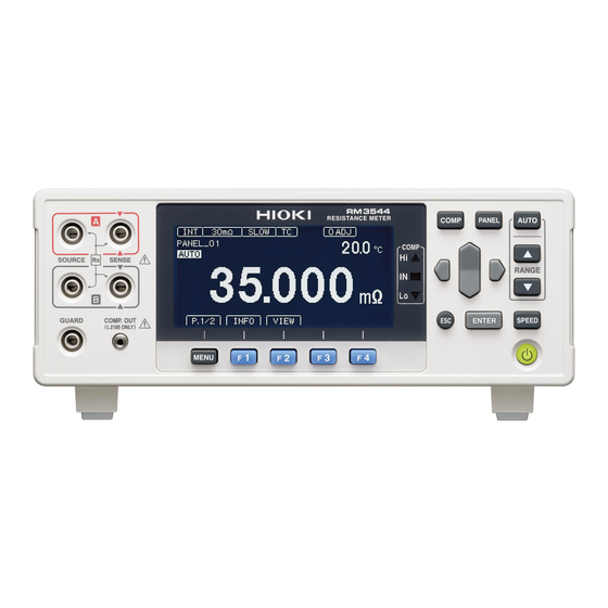
RM3545 RM3545-01 RM3545-02
This manual explains the communication commands for Models RM3544 / RM3545 /
RM3545A Resistance Meter.
Please refer to the instruction manual for Models RM3544 / RM3545 / RM3545A for
details regarding command settings.
Although all reasonable care has been taken in the production of this instruction manual,
should you find any points which are unclear or in error, please contact your local
distributor or HIOKI's website.(https://www.hioki.com/contact)
In the interest of product development, the contents of this manual may be subject to
revision without notice.
Unauthorized copying and replication of the contents of this instruction manual are strictly
prohibited. All Rights Reserved.
RM3545A-1 RM3545A-2
RESISTANCE METER
HIOKI RM3544A986-04
RM3544-01
November 2023 RM3544A986-04
Advertisement
Table of Contents

Related Manuals for Hioki RM3544-01


Summary of Contents for Hioki RM3544-01
- Page 1 Although all reasonable care has been taken in the production of this instruction manual, should you find any points which are unclear or in error, please contact your local distributor or HIOKI’s website.(https://www.hioki.com/contact) In the interest of product development, the contents of this manual may be subject to ...
-
Page 2: Table Of Contents
:READ :MEASure:RESistance :MEASure:RESistance:LP :MEASure:TEMPerature :ABORt (3) Zero Adjustment .......................... 32 :ADJust :ADJust:CLEar :ADJust:STATe :ADJust:ENABle (4) Measurement Speed ........................33 :SAMPle:RATE (5) Averaging Function ........................33 :CALCulate:AVERage:STATe :CALCulate:AVERage:COUNt (6) Comparator ..........................33 :CALCulate:LIMit:STATe :CALCulate:LIMit:BEEPer :CALCulate:LIMit:MODE :CALCulate:LIMit:UPPer :CALCulate:LIMit:LOWer :CALCulate:LIMit:REFerence :CALCulate:LIMit:PERCent HIOKI RM3544A986-04... - Page 3 :MEMory:STATe :MEMory:CLEar :MEMory:COUNt :MEMory:DATA (14) Hold ............................. 42 [:SENSe:]HOLD:AUTO [:SENSe:]HOLD:STATe [:SENSe:]HOLD:OFF (15) Multiplexer Settings RM3545 RM3545A ..................43 [:SENSe:]WIRE [:SENSe:]SCAN:MODE [:SENSe:]SCAN:STATe [:SENSe:]SCAN:RESet [:SENSe:]SCAN:FAIL:STOP [:SENSe:]SCAN:DATA [:SENSe:]FRONtcheck? [:SENSe:]CH [:SENSe:]CH:STATe [:SENSe:]CH:AVAirable [:SENSe:]INSTrument [:SENSe:]TERMinal (16) Multiplexer Channel Reset RM3545 RM3545A ................ 46 HIOKI RM3544A986-04...
- Page 4 :SYSTem:PANel:CLEar (32) Key-Lock ............................59 :SYSTem:KLOCk (33) Line Frequency ..........................59 :SYSTem:LFRequency (34) Clock RM3545 RM3545A ......................59 :SYSTem:DATE :SYSTem:TIME (35) Key Beeper ..........................60 :SYSTem:BEEPer:STATe (36) Communications Settings ......................60 :SYSTem:LOCal :SYSTem:DATAout :SYSTem:HEADer :SYSTem:TERMinator :SYSTem:COMMunicate :SYSTem:COMMunicate:MONitor :SYSTem:COMMunicate:LAN:IPADdress HIOKI RM3544A986-04...
- Page 5 Measurement by external trigger 2 ..................... 75 LAN communication setting example RM3545A ................ 75 7 Sample Programs ............................ 76 Using Visual Basic ..........................76 Using Visual C# ............................84 8 Device Compliance Statement [GP-IB] ....................93 HIOKI RM3544A986-04...
-
Page 6: Introduction
1 Introduction In this publication, items relevant only to the RM3544-01 are indicated as RM3544, and items relevant only to the RM3545, RM3545-01, and RM3545-02 are indicated as RM3545, and items relevant only to the RM3545A-1, RM3545A-2 are indicated as RM3545A. Also, the RM354-01, RM3545, RM3545-01, RM3545-02, RM3545A-2, , and RM3545A-2 are indicated as “the instrument.”... - Page 7 As shown by the following examples, a query is formed by appending a question mark “ ” after a program header. :FETCh? :CALCulate:LIMit:REFerence? Characters within square brackets [ ] may be omitted. Either form is valid [:SENSe:]RESistance:RANGe :SENSe:RESistance:RANGe RESistance:RANGe HIOKI RM3544A986-04...
- Page 8 In a message consisting of both a header and data, the header is separated from the data by a space “ ” (ASCII code 20H). :SYSTEM:HEADER OFF (3) Data Separator In a message containing multiple data items, commas are required to separate the data items from one another. :CALCulate:LIMit:BEEPer IN,1,0 HIOKI RM3544A986-04...
- Page 9 The instrument does not fully support IEEE 488.2. As much as possible, please use the data formats shown in the Reference section. Also, be careful to avoid constructing single commands line that could overflow the input buffer or output queue. HIOKI RM3544A986-04...
-
Page 10: Output Queue And Input Buffer
If 256 bytes are allowed to accumulate in this buffer so that it becomes full, the USB and GP-IB interface bus enters the waiting state until space is cleared in the buffer. The RS-232C interface will not accept data beyond 256 bytes. Note: Ensure that the no command ever exceeds 256 bytes. HIOKI RM3544A986-04... -
Page 11: Status Byte Register
Note: SRQ (Service Request) is a GP-IB function only. However, STB (Status Byte Register) information can be acquired with RS-232C/USB/LAN using the *STB? command. [RS-232C/USB/LAN] RS-232C/USB/LAN does not provide a function for issuing service requests. Still, SRER setup and STB reading are available. HIOKI RM3544A986-04... - Page 12 This is the logical sum of Event Status Register 0. Service Request Enable Register (SRER) This register masks the Status Byte Register. Setting a bit of this register to 1 enables the corresponding bit of the Status Byte Register to be used. HIOKI RM3544A986-04...
-
Page 13: Event Registers
Bit 1 (unused) Operation Complete This bit is set to 1 in response to an “ *OPC ” command. Bit 0 ・ It indicates the completion of operations of all messages up to the “ *OPC ” command HIOKI RM3544A986-04... - Page 14 Event Status Registers 0 and 1 are cleared in the following situations: • When a command is executed :ESR0? :ESR1? • When an Event Status Register query ( ) is executed • When the instrument is powered on HIOKI RM3544A986-04...
- Page 15 & & & & & & & & ↑ ↑ ↑ ↑ ↑ ↑ ↑ ↑ bit7 bit6 bit5 bit4 bit3 bit2 bit1 bit0 CONC CONC CURR UNIT ACT A ACT B Event Status Enable Register 1 (ESER1) HIOKI RM3544A986-04...
-
Page 16: Initialization Items
Output Queue Input buffer Status Byte Register *1 *2 Event registers *3 Enable register Current path Headers on/off HIOKI RM3544A986-04... -
Page 17: Command Execution Time
When message syntax (spelling) is invalid When the data format in a command or query is invalid • Query Error When the response message exceeds 64 bytes • Execution Error When invalid character or numeric data is present HIOKI RM3544A986-04... -
Page 18: Message List
Waits for trigger and reads the value>) measured value. RM3545/RM3545A :<NDAT RM3545/RM3545A : :READ? a/JUDGe> √ √ √ Responds with the total judgment or PASS/FAIL result only if For scanning OFF/STEP:(< NDATa is included in the data Measured value>) formats. For AUTO scanning:([< HIOKI RM3544A986-04... - Page 19 Queries the upper threshold. :CALCulate:LIMit:LOWer <Lower threshold> √ √ √ √ √ Sets the lower threshold. :CALCulate:LIMit:LOWer? (<Lower threshold>) √ √ √ √ √ Queries the lower threshold. :CALCulate:LIMit:REFerence <Reference resistance> √ √ √ √ √ Sets the reference resistance. HIOKI RM3544A986-04...
- Page 20 Queries the minimum value. no.>) (<Hi count>,<IN count>,<Lo :CALCulate:STATistics:LIMit? count>,<Measurement fault √ √ Queries the comparator results. count> (<BIN0 count>,...,<BIN9 :CALCulate:STATistics:BIN? count>,<OUT count>, √ √ Queries the BIN result. <Measurement fault count>) :CALCulate:STATistics:DEViati (<σn>,<σn-1>) √ √ Queries the standard deviation. HIOKI RM3544A986-04...
- Page 21 [:SENSe:]WIRE 4/2/W4/W2 Sets the measurement method. Queries the measurement √ √ [:SENSe:]WIRE? (W4/W2) method. √ √ [:SENSe:]SCAN:MODE OFF/AUTO/STEP Sets the scanning function. √ √ [:SENSe:]SCAN:MODE? (OFF/AUTO/STEP) Queries the scanning function. √ √ [:SENSe:]SCAN:STATe? Queries the scanning execution (1/0) HIOKI RM3544A986-04...
- Page 22 Sets the resistance measurement 1/0/ON/OFF √ √ √ √ √ AUTO AUTO range. [:SENSe:]RESistance:RANGe: Queries the resistance (ON/OFF) √ √ √ √ √ AUTO? measurement AUTO range. [:SENSe:]RESistance:LP:RAN 0 to 1000E+0 √ √ √ √ Sets the Low-Power Resistance HIOKI RM3544A986-04...
- Page 23 (THERMISTOR/ANALOG) √ √ Queries the temperature sensor. [:SENSe:]TEMPerature:PARam Sets the analog input scaling <V1>,<T1>,<V2>,<T2> √ √ eter constants. [:SENSe:]TEMPerature:PARam Queries the analog input scaling (<V1>,<T1>,<V2>,<T2>) √ √ eter? constants. Trigger 1/0/ON/OFF √ √ √ :INITiate:CONTinuous Sets the continuous HIOKI RM3544A986-04...
- Page 24 Sets the command delimiter. :SYSTem:TERMinator? (0/1) √ √ Queries the command delimiter. Sets the Communication :SYSTem:COMMunicate USB/LAN/RS232c/PRINter √ interface (USB/LAN/RS232C/PRINR Queries the Communication :SYSTem:COMMunicate? √ interface :SYSTem:COMMunicate:MONi 1/0/ON/OFF √ Sets the Communication monitor :SYSTem:COMMunicate:MONi Queries the Communication (ON/OFF) √ tor? monitor HIOKI RM3544A986-04...
- Page 25 Multiplexer Unit <Unit number> :UNIT:IDN? (<Model name>,<Serial √ √ Queries the unit. number>) <Unit number> :UNIT:SCOunt? √ √ Queries the relay usage count. (<Relay count>) :UNIT:TEST? <Unit number> (<0 to 8>) √ √ Queries the unit test and result. HIOKI RM3544A986-04...
-
Page 26: Message Reference
PON URQ CME EXE DDE QYE RQC OPC *ESE 36 Example Shows an example of an (Sets bits 5 and 2 of SESER) actual command application. (Normally described with HEADER OFF [except the HEADER command itself].) Command, Query Instrument Controller Response HIOKI RM3544A986-04... -
Page 27: Standard Commands
<Software version> Example *IDN? HIOKI,RM3545,123456789,V1.00 The Device ID is HIOKI RM3545, 123456789, software version 1.00. The <Model name> includes the following devices in addition to the example RM3544-01, RM3545-01, RM3545-02, RM3545A-1 and RM3545A-2 . Note The response message has no header. -
Page 28: Synchronization Commands
NR1 value (0 to 255). bit 7 bit 6 bit 5 bit 4 bit 3 bit 2 bit 1 bit 0 PON URQ CME EXE DDE QYE RQC OPC Example *ESE 36 (Sets bits 5 and 2 of SESER) HIOKI RM3544A986-04... -
Page 29: Esr
5 bit 4 bit 3 bit 2 bit 1 bit 0 ESB1 ESB0 unused unused unused Example *SRE Set SRER bits 0 and 5 to 1. *SRE? SRER bits 0 and 5 have been set to 1. HIOKI RM3544A986-04... -
Page 30: Stb
Event Status Register. bit 7 bit 6 bit 5 bit 4 bit 3 bit 2 bit 1 bit 0 OutBIN OvrRng ERR INDEX Note Data initializes to zero at power-on. RES:ERR:CURR OVER OvrRng and ERR can not be Changed by HIOKI RM3544A986-04... -
Page 31: Esr0
± □□. □□□ E+00 ±10.000E+19 10.000E+29 300Ω ± □□□. □□ E+00 ±100.00E+18 100.00E+28 3kΩ ± □. □□□□ E+03 ±1.0000E+20 1.0000E+30 30kΩ ± □□. □□□ E+03 ±10.000E+19 10.000E+29 300kΩ ± □□□. □□ E+03 ±100.00E+18 100.00E+28 3MΩ ± □. □□□□ E+06 ±1.0000E+20 1.0000E+30 HIOKI RM3544A986-04... - Page 32 Note: For positive measured values, a space (ASCII 20H) represents the sign. Time to receive measured values is different for the :FETCh? and :READ? commands. See: Data Exporting Methods (p.71), Triggering (p.53) Also see “4 Multiplexer Commands (p.67)” for the multiplexer unit. HIOKI RM3544A986-04...
- Page 33 • When the front terminal is used or the scanning function is OFF, JUDGe or LIMJdge is selected as the data. • When the front terminal is used, a channel number is specified for the data. • During auto scanning HIOKI RM3544A986-04...
-
Page 34: Fetch:temperature
[:SENSe:]CH:AVAilable? query. If a measurement has not been performed, the value for a measurement fault is returned. STEP One channel is measured when a trigger is received. A response is returned after one channel is measured. HIOKI RM3544A986-04... - Page 35 • An execution error occurs when the auto range is turned ON if the comparator function and BIN measurement function are ON. • When the scanning function is set to STEP or AUTO, an execution error occurs. HIOKI RM3544A986-04...
-
Page 36: Measure:resistance:lp
/Scan measurement/Scan zero adjustment is abort (forced Executes :READ ermination). Example :READ? :ABOR Executes an abort. Note An abort cannot be executed as the instrument waits until all prior commands finish if the query is sent after command. *WAI HIOKI RM3544A986-04... -
Page 37: Zero Adjustment
Query Zero Adjustment Execution State RM3545 RM3545A Syntax :ADJust:STATe? Query Response <ON/OFF> Example CH 10 :ADJ:STAT? Set and Query Scan Zero Adjustment Execution RM3545 RM3545A Syntax :ADJust:ENABle Command <1/0/ON/OFF> :ADJust:ENABle? Query Response <ON/OFF> Example CH 10 :ADJ:ENAB ON :ADJ:ENAB? HIOKI RM3544A986-04... -
Page 38: Measurement Speed
<1/0/ON/OFF> :CALCulate:LIMit:STATe? Query Response <ON/OFF> Example :CALC:LIM:STAT ON :CALC:LIM:STAT? Note When the comparator is executed, the auto range , the temperature conversion function and BIN function enter the OFF state. RM3545 RM3545A An execution error occurs during scanning. HIOKI RM3544A986-04... -
Page 39: Calculate:limit:beeper
<Lower threshold[Ω]> = 0 to 9E+9 (NR3) Example :CALC:LIM:LOW 0.9 The lower threshold is 0.9Ω (regardless of range). Note The value will be 0 when the lower threshold is less than 1E-9. RM3545 RM3545A An execution error occurs during scanning. HIOKI RM3544A986-04... -
Page 40: Calculate:limit:reference
… Obtains the comparator result of Channel 10 Set and Query PASS Judgment Condition RM3545 RM3545A Syntax :CALCulate:LIMit:JUDGe:CONDition Command <Condition> :CALCulate:LIMit:JUDGe:CONDition? Query Response <Condition> <Condition> = OFF/IN/HI/LO/HILO/ALL Example :CALC:LIM:JUDG:COND IN :CALC:LIM:JUDG:COND? Note An execution error occurs during scanning. HIOKI RM3544A986-04... -
Page 41: Calculate:limit:judge
“1” will be the BIN number bit used to execute the BIN measurement. bit9 bit8 bit7 bit6 bit5 bit4 bit3 bit2 bit1 bit0 BIN9 BIN8 BIN7 BIN6 BIN5 BIN4 BIN3 BIN2 BIN1 BIN0 Example :CALC:BIN:ENAB 15 BIN0 to BIN3 can be used. HIOKI RM3544A986-04... -
Page 42: Calculate:bin:mode
When the reference resistance is less than 1E-9, a command error occurs. Set and Query REF% Mode Judgment Range Syntax :CALCulate:BIN:PERCent Command <BIN No.>,<Range[%]> :CALCulate:BIN:PERCent? Query <BIN No.> Response <Range[%]> <BIN No.> = 0 to 9 <Range[%]> = 0 to 99.999 (NR2) Example :CALC:BIN:PERC 0,1.5 HIOKI RM3544A986-04... -
Page 43: Calculate:bin:result
Syntax :CALCulate:STATistics:CLEar Command Query Data Count Syntax :CALCulate:STATistics:NUMBer? Query Response <Total data count (NR1)>,<Valid data count (NR1)> Data count = 0 to 30000 Example :CALC:STAT:NUMB? 23456,23449 Query Mean Value Syntax :CALCulate:STATistics:MEAN? Query Response <Mean[Ω] (NR3)> Example :CALC:STAT:MEAN? 11.4859E+03 HIOKI RM3544A986-04... -
Page 44: Calculate:statistics:maximum
Query Process Capability Indices Syntax :CALCulate:STATistics:CP? Query Response <Cp (NR2)>,<Cpk (NR2)> Example CALC:STAT:CP? 0.86,0.14 (9) Scaling RM3545 RM3545A An execution error occurs during scanning. Execute and Query Scaling Function Syntax :CALCulate:SCALing:STATe Command <1/0/ON/OFF> :CALCulate:SCALing:STATe? Query Response <ON/OFF> Example :CALC:SCAL:STAT ON :CALC:SCAL:STAT? HIOKI RM3544A986-04... -
Page 45: Calculate:scaling:parametera
<Initial resistance [Ω] >,<Initial temperature >,<Constant > <Initial resistance [Ω] > = 0 to 9000.000E+6 (NR3) [ᵒC] > = -10.0 to 99.9 (NR2) <Initial temperature [ᵒC] > = -999.9 to 999.9 (NR2) <Constant Example :CALC:TCON:DELT:PAR 100,20,235 :CALC:TCON:DELT:PAR? 100.000E+0,20.0E+0,235.0 HIOKI RM3544A986-04... -
Page 46: Temperature Correction (Tc)
Syntax :DISPlay:CONTrast Command <0 to 100> :DISPlay:CONTrast? Query Response <0 to 100 (NR1)> Example :DISP:CONT 80 :DISP:CONT? Set and Query Backlight Syntax :DISPlay:BACKlight Command <0 to 100> :DISPlay:BACKlight? Query Response <0 to 100 (NR1)> Example :DISP:BACK 50 :DISP:BACK? HIOKI RM3544A986-04... -
Page 47: Memory Functions Rm3545 Rm3545A
An execution error occurs during scanning. Execute and Query Auto Hold Syntax [:SENSe:]HOLD:AUTO Command <1/0/ON/OFF > [:SENSe:]HOLD:AUTO? Query Response <ON/OFF> Example HOLD:AUTO ON HOLD:AUTO? Note :INITIATE:CONTINUOUS ON When auto hold is executed, and internal trigger (trigger source <IMMEDIATE>) are enabled. HIOKI RM3544A986-04... -
Page 48: [:Sense:]Hold:state
Responds with whether scanning is being executed or not. 0 is returned when the scanning function is OFF or scanning is paused. 1 is returned during auto scanning or step scanning. 2 is returned during the scanning and the measuring. HIOKI RM3544A986-04... -
Page 49: [:Sense:]Scan:fail:stop
[:SENSe:]CH:AVAirable? query. If a measurement has not been performed, the value for a measurement fault is returned. See: “Measurement Value Formats” (p.26) Example CH:AVA? SCAN:DATA? 1023.579E-00,1000.000E-03, 100.0000E-03 Note An execution error occurs during scanning. HIOKI RM3544A986-04... -
Page 50: [:Sense:]Ch
An execution error occurs during scanning. Set and Query Multiplexer Channel Syntax [:SENSe:]CH:STATe <1/0/ON/OFF>[,<Channel number>] Command [:SENSe:]CH:STATe? [<Channel number>] Query Response <ON/OFF> <Channel number> = 1 to 42 (NR1) Example CH:STAT ON,10 CH:STAT? 10 Note An execution error occurs during scanning. HIOKI RM3544A986-04... -
Page 51: Multiplexer Channel Reset Rm3545 Rm3545A
An execution error occurs during scanning. Execute Multiplexer Channel Reset Syntax [:SENSe:]CHReset Command Description Initializes the multiplexer channel settings including the measurement conditions. Note An execution error occurs when the front terminal is used as a measurement terminal or during scanning. HIOKI RM3544A986-04... -
Page 52: Low-Power Resistance Measurement Rm3545 Rm3545A
When the scaling function is being used, set the <Expected measurement value> to the value that existed prior to scaling (value in range being used). When a range is set, the auto-range function will be automatically turned off. HIOKI RM3544A986-04... -
Page 53: [:Sense:]Resistance:range
(value in range being used). Query Queries the measurement range setting. The setting will be that of Low-Power ON. For the Low-Power OFF setting, use: [:SENSe:]RESistance:RANGe [:SENSe:]RESistance:RANGe? Example RES:LP:RANG? 1000.00E+00 Low-Power Resistance measurement has been set to the 1000mΩ range. HIOKI RM3544A986-04... -
Page 54: 100Mω Range High Precision Function Rm3545 Rm3545A
√ 1000 mΩ 100 mA 10 mA √ √ 10 Ω 10 mA 1 mA √ √ 100 Ω 10 mA 1 mA *1:PR mode is RM3545A only *2:500 mA is RM3546 only Example :RES:CURR HIGH :RES:CURR? HIGH HIOKI RM3544A986-04... -
Page 55: Offset Voltage Correction Function (Ovc) Rm3545 Rm3545A
When Low-Power is ON, the query response will definitely be OFF. (24) Current Error Mode An execution error occurs during scanning. Set and Query Current Error Mode Syntax [:SENSe:]RESistance:ERRor:CURRentcheck Command <ERRor/OVER> [:SENSe:]RESistance:ERRor:CURRentcheck? Query Response <ERROR/OVER> <ERROR> = Current error <OVER> = Out-of-range Example RES:ERR:CURR ERR RES:ERR:CURR? ERROR HIOKI RM3544A986-04... -
Page 56: Sense:resistance:error:over
RM3544 <Number of digits> = 4/5 (NR1) RM3545 RM3545A <Number of digits> = 5/6/7 (NR1) Example :RES:DIG 5 :RES:DIG? Note When Low-Power is ON, six (6) digits will actually be displayed even when the number of digits is set to seven (7). HIOKI RM3544A986-04... -
Page 57: Temperature Measurement (Analog Input) Rm3545 Rm3545A
<V2> = 0 to 2.00 (NR2) ......Reference voltage 2 [V] <T2> = -99.9 to 999.9 (NR2) ....Reference temperature 2 [°C] Example TEMP:PAR 0,-10,2,100 TEMP:PAR? 0.00,0.00,1.00,100.0 0°C is displayed with 0 V, and 100°C is displayed with 1 V. HIOKI RM3544A986-04... -
Page 58: Triggering
After measurement, enters the trigger wait state. Idle State Trigger Wait State :INITIATE:IMMEDIATE or :READ? TRIG signal, [ENRER] key, Trigger Wait State *TRG TRIG signal Trigger Delay Trigger Delay Measurement Measurement Calculation Calculation Measured Value Output Measured Value Output HIOKI RM3544A986-04... - Page 59 Idle State Trigger Wait State :INITIATE:IMMEDIATE TRIG siglnal, [ENTER] key, or or :READ? *TRG Trigger Wait State Channel 1 measurement TRIG signal Channel 2 measurement ・・・ Channel 1 measurement Channel 2 measurement Channel n measurement ・・・ Channel n measurement HIOKI RM3544A986-04...
- Page 60 If this has been set to OFF, when operation is returned to the Local state or power is turned off, :INITIATE:CONTINUOUS ON state occurs when power is turned back on. p.71) “Return to Local Control” (p.60) or Exporting measured values: “Data Exporting Methods” ( HIOKI RM3544A986-04...
- Page 61 Set and Query Trigger Source Syntax :TRIGger:SOURce Command <IMMediate/EXTernal> :TRIGger:SOURce? Query Response <IMMEDIATE/EXTERNAL> <IMMEDIATE> = Internal triggering <EXTERNAL> = External triggering Example :TRIG:SOUR IMM :TRIG:SOUR? IMMEDIATE Note RM3545 RM3545A An execution error occurs during scanning. HIOKI RM3544A986-04...
-
Page 62: Trigger:edge
An execution error occurs during scanning. Execute Self-Calibration Syntax :SYSTem:CALibration Command Note If this command is received while measuring, self-calibration executes after the measurement is finished. Execute and Set Self-Calibration Syntax :SYSTem:CALibration:AUTO Command <1/0/ON/OFF> :SYSTem:CALibration:AUTO? Query Response <ON/OFF> HIOKI RM3544A986-04... -
Page 63: Saving And Reading Measurement Conditions
For information on character string data, see Data Formats. (p.4) Example :SYST:PAN:NAME 1,“PANEL_1” :SYST:PAN:NAME? 1 1,“PANEL_1” Clear Panel Syntax :SYSTem:PANel:CLEar Command <Table No> RM3544 <Table No> = 1 to 10 (NR1) RM3545 RM3545A <Table No> = 1 to 38 (NR1) Example :SYST:PAN:CLE 10 HIOKI RM3544A986-04... -
Page 64: Key-Lock
Sets the date to January 10, 2013. :SYST:DATE? 13,12,10 The date is December 10, 2013. Note Attempting to set an out-of-range numerical value returns an execution error. Attempting to set a non-existent date (such as 13,06,31) returns an execution error. HIOKI RM3544A986-04... -
Page 65: System:time
When there is an internal trigger (trigger source <IMMEDIATE>), measurement values are automatically sent when the [ENTER] key is pressed and TRIG signal have been input. <OFF> = Measured values are not automatically sent. Note This command is not applicable to the GP-IB Interface. HIOKI RM3544A986-04... -
Page 66: System:header
Changes the interface upon receiving a command. (Communication during command will be disconnected) Set and Query Command Monitor Syntax :SYSTem:COMMunicate:MONitor Command <1/0/ON/OFF> :SYSTem:COMMunicate:MONitor? Query Response <ON/ OFF> <1/ON> = display ON <0/OFF> =display OFF Description Configure the command monitor. Note HIOKI RM3544A986-04... -
Page 67: System:communicate:lan:ipaddress
Syntax :SYSTem:COMMunicate:LAN:CONTrol Command <port NO.> :SYSTem:COMMunicate:LAN:CONTrol? Query Response <port NO.> <port No.> = 11~65535(80 is excluded) Description Sets and queries the LAN port number. Example :SYST:COMM:LAN:CONT 3545 :SYST:COMM:LAN:UPD :SYST:COMM:LAN:CONT? 3545 Note Updates are reflected when you run ":SYSTem:COMMunicate:LAN:UPDate" HIOKI RM3544A986-04... -
Page 68: System:communicate:lan:mac
Example :SYST:COMM:RS232C 9600 :SYST:COMM:RS232C:SPEED? 9600 Note (37) System Reset RM3545 RM3545A An execution error occurs during scanning. Execute System Reset Syntax :SYSTem:RESet Command Description Initializes all except communications and clock settings. After initialization, panel data, too, is initialized. HIOKI RM3544A986-04... -
Page 69: Ext I/O
:IO:FILTer:STATe? Query Response <ON/OFF> Example :IO:FILT:STAT ON :IO:FILT:STAT? Set and Query TRIG/PRINT Signal's Filter Time Syntax :IO:FILTer:TIME Command <Filter time> :IO:FILTer:TIME? Query Response <Filter time> <Filter time> = 0.05 to 0.50 (NR2) [sec] Example :IO:FILT:TIME 0.1 :IO:FILT:TIME? 0.10 HIOKI RM3544A986-04... -
Page 70: Io:judge:mode
<PULSE> = Sets EOM=OFF according to the specified pulse width. Example :IO:EOM:MODE PULS :IO:EOM:MODE? PULSE Set and Query EOM Pulse Width Syntax :IO:EOM:PULSe Command <Pulse width> :IO:EOM:PULSe? Query Pulse width (NR2) Response < > <Pulse width> = 0.001 to 0.100 (NR2) [sec] Example :IO:EOM:PULS 0.005 :IO:EOM:PULS? 0.005 HIOKI RM3544A986-04... -
Page 71: Multiplexer Unit Rm3545 Rm3545A
Replace the fuse and execute the test again. NO UNIT(8) The unit is not inserted. Insert the unit and execute the test again. For information on unit test, see the instrument instruction manual. Example :UNIT:TEST? 1 Note RM3545 RM3545A An execution error occurs during scanning. HIOKI RM3544A986-04... -
Page 72: Multiplexer Commands
:CALC:LIM:UPP 10E-03 :CALC:LIM:LOW 1E-03 :CALC:LIM:JUDG:COND IN CH 2 Channel 2 settings TERM 1,3,4 Measures between Unit 1 TERM 3 and TERM 4 RES:RANG 10E-03 Sets the range. :CALC:LIM:STAT ON Sets the comparator. :CALC:LIM:UPP 8E-03 :CALC:LIM:LOW 3E-03 :CALC:LIM:JUDG:COND IN HIOKI RM3544A986-04... -
Page 73: Multiplexer Measurement
Obtains the comparator result of each channel. :CALC:LIM:RES? 2 :CALC:LIM:JUDG? 1 Obtains the PASS/FAIL result of each channel. FAIL :CALC:LIM:JUDG? 2 PASS :CALC:LIM:JUDG:TOT? Obtains the total judgment result. FAIL :READ? NDAT Executes scanning (all channels measured). FAIL Reads the total judgment result. HIOKI RM3544A986-04... - Page 74 CH:STAT ON,2 CH:STAT ON,3 (External trigger input) Executes scanning. Reads the measured values and :FETC? 1 judgment values of all channels. 1020.000E-03 :FETC? LIM,2 100.000E-03,HI :FETC? JUDG,3 100.000E-03,PASS :SCAN:DATA? Reads the measured values of all 1020.000E-03, 100.000E-03, 100.000E-03 channels. HIOKI RM3544A986-04...
- Page 75 Reads the measured values and judgment values of all :FETC? 1 channels. 1020.000E-03 :FETC? LIM,2 100.000E-03,HI :FETC? JUDG,3 100.000E-03,PASS :SCAN:DATA? Reads the measured values of all channels. 1020.000E-03, 100.000E-03, 100.000E-03 SCAN:RES Clears the measured value and switches to Channel 1. HIOKI RM3544A986-04...
-
Page 76: Data Exporting Methods
Default Setting (continuous measurement disable) :TRIGger:SOURce EXT (external triggering) :READ? Exporting When triggered by the [ENTER] Key or TRIG signal, a measurement is performed and the result is transferred. :INITiate:CONTinuous OFF Note When :READ? is sent, automatically occurs. HIOKI RM3544A986-04... - Page 77 Start Single Measurement Command Processing Returns the measured value after single measurement to the PC Response Use this method to measure (and export) synchronously with the controller (PC, PLC) or external trigger signal. Measurement time can be minimized. HIOKI RM3544A986-04...
- Page 78 When the scanning function is set to AUTO or STEP, the measured values of all channels are obtained with the SCAN:DATA? command after scanning. Measurement Scan measurement Channel 1 Channel 2 Channel 3 Measured Value measurement value measurement value measurement value Command Processing SCAN:DATA? Returns the measured values Response of all channels to the PC HIOKI RM3544A986-04...
-
Page 79: Examples Of Communication Commands
You can also download sample programs compatible with various programming languages from our website. Please refer to this when creating communication programs for measuring instruments. Please search for Sample program for communication with HIOKI products on an internet search site. Confirmation before measurement ... -
Page 80: Measurement By External Trigger 1
Setting the default gateway :SYST:COMM:LAN:GAT 172,16,1,1 Setting the port number :SYST:COMM:LAN:CONT 523 Confirming LAN settings :SYST:COMM:LAN:UPD (LAN restart) Check IP address :SYST:COMM:LAN:IPAD? 172,16,1,100 Check subnet mask :SYST:COMM:LAN:SMASk? 255,255,255,0 Checking the default gateway :SYST:COMM:LAN:GAT? 172,16,1,1 Check port number :SYST:COMM:LAN:CONT? HIOKI RM3544A986-04... -
Page 81: Sample Programs
Note: Depending on the environment of the PC and VB2022, the procedure may differ slightly from the one described here. For a detailed explanation on how to use VB2022, refer to the instruction manual or Help of VB2022. 1. Create a new project. 1. Startup Visual Studio. 2. Select [Create a new project]. Click HIOKI RM3544A986-04... - Page 82 3. Select [Visual Basic]-[Windows]-[Desktop]-[Windows Forms App (.NET Framework)] from the templates. Click Click 4. Click [Next]. 5. Click [Create]. Click HIOKI RM3544A986-04...
- Page 83 2. Place a button. 1. Click [Button] from [Common Controls] of [Toolbox]. Click Drag 2. Drag and drop the button onto the form layout screen. 3. Change [Text] to “Start Measurement” from the Properties window. HIOKI RM3544A986-04...
- Page 84 4. The [Start Measurement] is placed on the form. 3. Place a serial communication component. 1. Click [SerialPort] from [Components] of [Toolbox]. Click HIOKI RM3544A986-04...
- Page 85 2. Drag and drop the [SerialPort] component onto the form layout screen. Drag 3. Change [PortName] to the port name to use for communication from the properties window. Check the port to use for communication beforehand. HIOKI RM3544A986-04...
- Page 86 4. Describe the code. 1. Double-click the placed button to display the code editor. Double-click 2. Enter the sample program into the code editor. HIOKI RM3544A986-04...
- Page 87 When the [Begin Measurement] button is pressed, the instrument performs 10 measurements and writes the measurement values to a “data.csv” file. When the [X] button is pressed, the program closes. The following program is written entirely in [Form1] code. HIOKI RM3544A986-04...
- Page 88 MessageBox.Show(ex.Message, "Error", MessageBoxButtons.OK, MessageBoxIcon.Error) End Try End Sub 'Set measurement conditions Private Sub SendSetting(ByVal sp As SerialPort) sp.WriteLine(":TRIG:SOUR IMM") 'Select internal triggering sp.WriteLine(":INIT:CONT ON") 'Continuous measurement ON Catch ex As Exception MessageBox.Show(ex.Message, "Error", MessageBoxButtons.OK, MessageBoxIcon.Error) End Try End Sub End Class HIOKI RM3544A986-04...
-
Page 89: Using Visual C
Note: Depending on the environment of the PC and CS2022, the procedure may differ slightly from the one described here. For a detailed explanation on how to use CS2022, refer to the instruction manual or Help of CS2022. 1. Create a new project. 1. Startup Visual Studio. 2. Select [Create a new project]. Click HIOKI RM3544A986-04... - Page 90 3. Select [C#]-[Windows]-[Desktop]-[Windows Forms App (.NET Framework)] from the templates. Click Click 4. Click [Next]. 5. Click [Create]. Click HIOKI RM3544A986-04...
- Page 91 2. Place a button. 1. Click [Button] from [Common Controls] of [Toolbox]. Click Drag 2. Drag and drop the button onto the form layout screen. 3. Change [Text] to “Start Measurement” from the Properties window. HIOKI RM3544A986-04...
- Page 92 4. The [Start Measurement] is placed on the form. 4. Describe the code. 1. Double-click the placed button to display the code editor. Double-click HIOKI RM3544A986-04...
- Page 93 When the [Begin Measurement] button is pressed, the instrument performs 10 measurements and writes the measurement values to a “data.csv” file. When the [X] button is pressed, the program closes. The following program is written entirely in [Form1] code. HIOKI RM3544A986-04...
- Page 94 // Select internal triggering SendMsg(":INIT:CONT ON"); // Continuous measurement ON for (i = 1; i <= 10; i++) SendQueryMsg(":FETCH?"); // Get the latest measurement results fp.Write(MsgBuf + "\r\n"); // Write to file // Close the file fp.Close(); // Disconnection CloseInterface(); HIOKI RM3544A986-04...
- Page 95 // Send command private Boolean SendMsg(String strMsg) Boolean ret = false; Byte[] sendBuffer; strMsg += "\r\n"; // Add terminator "CR+LF" sendBuffer = Encoding.Default.GetBytes(strMsg); // Convert to byte type LanSocket.GetStream().Write(sendBuffer, 0, sendBuffer.Length); // Write to send buffer ret = true; HIOKI RM3544A986-04...
- Page 96 // Ignore terminator 'CR' else MsgBuf += Convert.ToChar(rcv[0]); // Save received data // Timeout processing if (sw.ElapsedMilliseconds > timeout) MsgBuf = "Timeout"; MessageBox.Show(MsgBuf); return ret; sw.Stop(); // Stop the stopwatch ret = true; catch (Exception e) MsgBuf = "Error"; MessageBox.Show(e.Message); HIOKI RM3544A986-04...
- Page 97 // Send and receive commands private Boolean SendQueryMsg(String strMsg, long timeout = Timeout_default) Boolean ret = false; ret = SendMsg(strMsg); // Send command if (ret) ret = ReceiveMsg(timeout); // Receive response after successful transmission return ret; HIOKI RM3544A986-04...
-
Page 98: Device Compliance Statement [Gp-Ib]
• Whether any queries produce responses when read: There are no queries which produce response messages when they are read in by the controller. • Whether any commands are coupled: There are no relevant commands. HIOKI RM3544A986-04... - Page 99 23. Criterion relating to the functions required at the Termination occurs when the command has been nstant that the termination message is produced, as a parsed. response to each command The :READ? query finishes when the measurement data is received. HIOKI RM3544A986-04...
- Page 100 HIOKI RM3544A986-04...
Need help?
Do you have a question about the RM3544-01 and is the answer not in the manual?
Questions and answers