
Related Manuals for Hioki CHT3548


Summary of Contents for Hioki CHT3548
- Page 1 CHT3548 User’s Manual RESISTANCE METER 2015-4-15 Hope Electronics Technology Manual Edition V1.0...
-
Page 2: Table Of Contents
Contents Introduction ........................4 Checking Package Contents ..................4 Safety Notes ........................5 Usage Notes ........................6 Chapter 1 Overview ......................9 1.1Overview and Features ...................9 1.2 Component Names and Operation Overview ..........10 1.3 Screen Layout ....................... 14 1.4 Checking the Measurement Target ..............18 1.5 Dimension ...................... - Page 3 7.5 Delete saved measurement data (clear memory) ........68 7.6 The saved measurement data read into the computer ......69 Chapter 8 System Settings..................71 8.1 confirmation screen displays the date and time ......... 71 8.2 calibration clock ....................71 8.3 initialized (reset) ....................
-
Page 4: Introduction
Introduction Thank you for purchasing the HIOKI RM3548 Resistance Meter. To obtain maximum performance from the product, please read this manual first, and keep it handy for future reference. Registered trademarks Windows and Excel are registered trademarks of Microsoft Corporation in the United States and/or other countries. -
Page 5: Safety Notes
Safety Notes The instrument is designed to conform to IEC 61010 Safety Standards, and has been thoroughly tested for safety prior to shipment. However, using the instrument in a way not described in this manual may negate the provided safety features. -
Page 6: Usage Notes
In this manual, the risk seriousness and the hazard levels are classified as follows. Indicates an imminently hazardous situation that will result in death or serious injury to the operator. Indicates a potentially hazardous situation that will result in death or serious injury to the operator. - Page 7 -10°C to 50°C 80%RH or less (no condensation) and humidity ranges Installing the instrument in inappropriate locations may cause a malfunction of instrument or may give rise to an accident. Avoid the following locations. Exposed to direct sunlight or high temperature Exposed to corrosive or combustible gases Exposed to water, oil, chemicals, or solvents Exposed to high humidity or condensation...
- Page 8 Measurement precautions To avoid electric shock accident and short circuit, please operate the instrument as following: Do not allow the instrument to get wet, and do not use it with wet hands. This may cause electric shock accident. Do not modify, disassemble, or repair the instrument.
-
Page 9: Chapter 1 Overview
Chapter 1 Overview 1.1Overview and Features The CHT3548 employs the four-terminal method to highly accurately measure the DC resistance of measurement targets including motor and transformer windings, and welding, PC board patterns, fuses, resistors, and materials such as conductive rubber. The instrument allows temperature correction and so is especially suitable for measurement targets whose resistance values change with temperature. -
Page 10: Component Names And Operation Overview
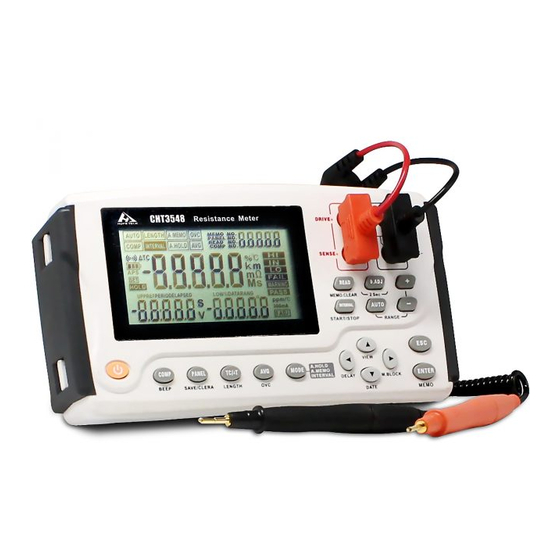
1.2 Component Names and Operation Overview Front Panel Rear Panel Rear panel Hope Electronics Technology Manual V1.0 Edition... - Page 11 Description [ COMP] Comparator: oFF — ON (ABS mode) — ON (REF% mode). [BEEPSET] key (press and hold) Judgment sound: oFF — Hi — in — Lo — Hi-Lo — ALL1 — ALL2. [PANEL] Panel load: Changes the panel No. “PrSEt” initializes the measurement conditions.
- Page 12 [▼]key Changes values and items. [DATE] key (press and hold) Displays the date and time confirmation screen. [ESC] Cancels the setting (when in the setting screen). Releases a HOLD state (if in a HOLD state). [ENTER] Applies the setting. [MEMORY] key (press and hold) Saves the measured values (manual memory).
- Page 13 Clearing all measurement data saved Resetting the current measurement conditions Resetting the system Hope Electronics Technology Manual V1.0 Edition...
-
Page 14: Screen Layout
1.3 Screen Layout Display (when the entire display is lit) Displays measurement conditions, settings, measured values, memory numbers (MEMORY No.), panel numbers, comparator settings, judgment results, etc. For information on the error display, see “Error display and actions” Resistance measurement screen Length conversion measurement screen Hope Electronics Technology Manual... - Page 15 Temperature conversion (ΔT) measurement screen Interval measurement screen Non-measured value display Out-of-range Current fault Hope Electronics Technology Manual V1.0 Edition...
- Page 16 The protection function is working Fuse blown out Indicator Description Lit: The zero adjustment function is enabled. Blinking: 0.ADJ Zero adjustment is in progress. The auto-hold function is enabled. A.HOLD The auto-memory function is enabled. A.MEMO The beeper function is enabled. The auto-power-save function is enabled.
- Page 17 The notation appears when using the data storage MEMO NO. function, showing the memory number. The notation appears when reading the saved data, READ NO. showing the read number of the data. The notation appears when doing the settings for each function.
-
Page 18: Checking The Measurement Target
1.4 Checking the Measurement Target To carry out proper resistance measurement, change the measurement conditions appropriately according to the measurement target. Before starting measurement, use the examples recommended in the following table to configure the instrument. l When the measurement target significantly depends on temperature, use the temperature correction function. -
Page 19: Dimension
1.5 Dimension Hope Electronics Technology Manual V1.0 Edition... -
Page 20: Chapter 1 Preparing For Measurement
Chapter 1 Preparing for Measurement 2.1 Attaching the Strap Attaching the strap to the instrument allows you to use it with the strap around your neck. Follow the procedure below to attach the strap. Note: Use the four attachment points on the instrument to attach the strap securely. -
Page 21: Loading Or Replacing The Batteries
2.2 Loading or Replacing the Batteries Before using the instrument for the first time, load the eight alkaline batteries (LR6). Before measurement, check that the instrument has sufficient remaining battery power. If the remaining battery level is low, replace the batteries. - Page 22 Lithium battery replacement Hope Electronics Technology Manual V1.0 Edition...
-
Page 23: Connecting The Test Leads
2.3 Connecting the Test Leads To avoid electric shock accident, connect the test leads correctly. To be safe, do not use any test lead other than the ones specified by our company. The ends of leads are sharp. Be careful to avoid injury. Connect the test leads to the instrument. - Page 24 A self-test is started. The model name and version number are displayed during the self-test. Turning the power off Press the key to turn the power off. Hold the key down until the [POWER] entire display turns off. Entire display off IMPORTANT When the instrument is turned on again, it starts up with the previous state used immediately before turning it off.
- Page 25 Then, when a specific time elapses after the start of blinking, the instrument automatically turns off. If no key is operated for 10 minutes or the instrument is in a measurement error state continuously, the APS indicator starts blinking. IMPORTANT During an interval measurement, the APS function automatically turns OFF.
- Page 26 Hope Electronics Technology Manual V1.0 Edition...
-
Page 27: Pre-Measurement Inspection
2.5 Pre-measurement Inspection Before using the instrument, inspect it to verify that no damage has occurred during storage or transportation and it operates normally. If you find any damage, contact your authorized Hopetech’s distributor or reseller. Instrument and peripheral checking Inspection item Action Is there any damage or a... -
Page 28: Chapter 3 Basic Measurement
Chapter 3 Basic Measurement Before measurement, be sure to read this chapter. 3.1 Setting the Measurement Range Select a measurement range. Automatic range selection (the auto range) is also available. IMPORTANT When the auto range is used or the measurement range is set to 30mO or less, a maximum current of 1 A may constantly flow through the measurement target, and a maximum power of approximately 2 W may be applied*. - Page 29 IMPORTANT When the range is manually changed in the auto range mode, the auto range is automatically disabled and the manual range is enabled. If the comparator function is turned ON, the range is fixed and cannot be changed. To change the range, turn the comparator function OFF or change the range in the comparator setting.
-
Page 30: Connecting The Test Leads To The Measurement Target
3.2 Connecting the Test Leads to the Measurement Target Example 9363-A Test clip Example 9363-B Test Probe Hope Electronics Technology Manual V1.0 Edition... -
Page 31: Reading The Measured Value
3.3 Reading the Measured Value The instrument displays a resistance value. If a non-resistance value is displayed, see "Verifying measurement errors". To convert the measured resistance value, see the following pages: “5.2 Performing Temperature Rise Test (Temperature Conversion Function (ΔT))" “5.3 Measuring the Length of a Conductor (Length Conversion Function)"... - Page 32 Verifying measurement errors If a measurement is not performed correctly, the measurement error is displayed on the screen. Out-of-range* Indicates that the measurement or display range has been exceeded. If oF is displayed, the comparator judgment is “Hi”, and if -oF is displayed, the comparator judgment is “Lo”.
- Page 33 If an overvoltage is applied to a measurement terminal, the function for protecting the internal circuitry is activated in this instrument. If an overvoltage is accidentally applied, remove the test leads from the measurement target immediately. Measurement cannot be performed while the protection function is activated.
- Page 34 Out-of-range detection Measurement examples measurement range 40 mΩis measured in the 30 mΩ range. exceeded. The relative display (% display) 5000 (+2400%) is measured with a of a measured value exceeds the reference value of 200. display range (999.99%). The A/D converter input range is Such an error occurs, for example, if a exceeded during a measurement.
- Page 35 Save a measured value The storage function helps to verify a measured value later. It saves the displayed measured value. For more details about the save function, see “Saving Data at Specified Time (Manual Memory)” Hope Electronics Technology Manual V1.0 Edition...
-
Page 36: Chapter 4 Customizing Measurement Conditions
Chapter 4 Customizing Measurement Conditions This chapter describes the functions useful to perform more sophisticated and accurate measurement. 4.1 Using Zero Adjustment In the following cases, perform zero adjustment: (A resistance of up to ±3%f.s. can be canceled for any range.) l The measurement value is not cleared due to thermal EMF or other factors. - Page 37 Performing zero adjustment 1 Short the test leads. Example 9363-A Test CliP Correct Incorrect Example 9363-B Text Probe 2. Confirm that the measured value is within ±3%f.s. If no measured value is displayed, make sure that the test leads are connected correctly.
- Page 38 If the connection is wrong 3. Press and hold the [0 ADJ] key to perform zero adjustment If it is difficult to press the key as the Zero Adjustment Board is used, press key before shorting the measurement lead. Zero adjustment is [0 ADJ] automatically performed after the measured value is stabilized.
- Page 39 Zero adjustment has failed The buzzer sounds and appears. Then, the measurement screen [FAIL] appears. Zero adjustment has failed When zero adjustment cannot be performed, the measured value before zero adjustment already exceeds ±3% of the full scale of each range or the instrument is in a measurement error state.
-
Page 40: Stabilizing Measured Values (Averaging Function)
4.2 Stabilizing Measured Values (Averaging Function) This function averages the measurement values in order to display a single value. It helps to stabilize fluctuations in the measured values. Hope Electronics Technology Manual V1.0 Edition... -
Page 41: Compensating For Thermal Effects (Temperature Correction (Tc))
4.3 Compensating for Thermal Effects (Temperature Correction (TC)) This function converts a measured resistance value, based on the reference temperature, to display the converted value. For the principles of temperature correction, see “Appx. Temperature Correction Function (TC)”. To perform temperature correction, connect the Temperature Sensor to the TEMP.SENSOR terminal on the side of the instrument. - Page 42 IMPORTANT If the “t.Err” is displayed, the Temperature Sensor may not be connected, or Of is displayed for the temperature. Check the connection of the Temperature Sensor. Hope Electronics Technology Manual V1.0 Edition...
-
Page 43: Compensating For Thermal Emf Offset (Offset Voltage Compensation Function: Ovc Function)
4.4 Compensating for Thermal EMF Offset (Offset Voltage Compensation Function: OVC Function) This function automatically compensates for an offset voltage caused by thermal EMF or an internal offset voltage. (OVC: Offset Voltage Compensation) See: “Appx. Effect of Thermoelectromotive Force (Thermal EMF)”. The function uses the resistance value measured when a measurement current flows, RP and that measured when no measurement current flows, RZ, to display the actual resistance value RP-RZ. -
Page 44: Setting The Delay Time For Measurement (Delay Function)
4.5 Setting the Delay Time for Measurement (Delay Function) This function adjusts the time for measurement to stabilize by inserting a waiting period after use of the OVC or the auto range function to change the measurement current. When this function is used, the instrument waits for its internal circuitry to stabilize before starting measurement, even if the measurement target has a high reactance component. - Page 45 Delay time guideline If the measurement target, for example, is an inductor that takes longer to stabilize after applying a measurement current, and it cannot be measured with the initial delay (preset), adjust the delay. Set the delay time to approximately ten times the following calculation so that the reactance component (inductance or capacitance) does not affect the measurement.
-
Page 46: Switching The Measurement Current (In The 300Mω Range)
4.6 Switching the Measurement Current (In the 300mΩ Range) With this instrument, the measurement current for the 300mQ range can be changed to 300 mA (100 mA at the time of shipment from the factory). This makes it possible to measure large current wiring under conditions that are similar to the actual usage conditions. - Page 47 l Even in a connection completely free from abnormality, a relatively high resistance may be indicated at a lower measurement current. This is due to an oxide film that is generated around the contact while it is not used. l Even when it is judged that no abnormality is found using a small current, the connection sections are occasionally melted when a large current flows.
-
Page 48: Chapter 5 Judgment And Conversion Functions
Chapter 5 Judgment and Conversion Functions This chapter describes the measured value judgment and conversion functions. 5.1 Judging Measured Values (Comparator Function) This function judges a measured value to be Hi (measured value > upper limit), IN (upper limit > measured value > lower limit), or Lo (lower limit > measured value) against the set reference value, or upper or lower limit values. - Page 49 -------- No judgment If the power is turned off during a setting process, any setting changes are lost and the previous values remain valid. To apply the changes, press the [ENTER] ABS (absolute value judgment) mode Set the upper and lower limit values for judgment, as absolute values. Example: Upper limit value……………..100.00 mΩ...
- Page 50 Judging based on upper and lower limit values (ABS mode) Hope Electronics Technology Manual V1.0 Edition...
- Page 51 IMPORTANT Any setting changes cannot be applied when: upper limit value<lower limit value. Judging based on a reference value and allowable range (REF% mode) In REF% mode, a measured value is displayed as a relative value. The upper and lower limit values cannot be set separately. Hope Electronics Technology Manual V1.0...
- Page 52 IMPORTANT The settings cannot be confirmed when the reference value is set to 0. Verifying a judgment with a sound (judgment sound function) This function sounds the buzzer, based on a comparator judgment result. Hope Electronics Technology Manual V1.0 Edition...
- Page 53 Hope Electronics Technology Manual V1.0 Edition...
-
Page 54: Performing Temperature Rise Test (Temperature Conversion Function (△T))
5.2 Performing Temperature Rise Test (Temperature Conversion Function (△T)) This function converts the change in the winding resistance into a temperature rise value, based on the temperature conversion principle (p. Appx.7). It can be used to estimate the temperature of the motor or the inside of the coil while the power is cut off based on the change in the winding resistance. -
Page 55: Measuring Conductor Length (Length Conversion Function)
Measurement screen 5.3 measuring conductor length (length conversion function) Hope Electronics Technology Manual V1.0 Edition... - Page 56 This function converts a resistance value to a length to display the length of the measurement target (such as a conductor). Press and hold the key to display the ON/OFF setting [TC/△T](LENGTH) screen for the length conversion function. Example: When the measured resistance is 8Ω and per meter resistance is 100mΩ/m IMPORTANT When length conversion function is set to ON, the comparator...
- Page 57 IMPORTANT The display format (decimal point position and unit) automatically changes depending on the range and setting. For details, see the product specifications. For some ranges, oF is always displayed, because the display range is exceeded, depending on the setting. Hope Electronics Technology Manual V1.0...
-
Page 58: Chapter 6 Panel Save And Load
Chapter 6 Panel Save and Load (Saving and Loading Measurement) The panel save function can save up to nine sets of measurement conditions displayed at the time of the panel save operation, and the panel load function can load any set of the measurement conditions at any time. The panel data is retained even if the instrument is turned off. -
Page 59: Reads The Measurement Conditions (Panel Reading Function)
IMPORTANT If the already saved panel number is selected and the key is [ENTER] pressed, the existing contents are overwritten. Zero adjustment values are not saved. 6.2 Reads the measurement conditions (panel reading function) This function replaces the current measurement conditions with a saved set of measurement conditions. - Page 60 IMPORTANT Once deleted, the contents of the panel cannot be restored. Hope Electronics Technology Manual V1.0 Edition...
-
Page 61: Chapter 7 Memory Function
Chapter 7 Memory function What the memory function does This function can save a value currently being measured. The saved data is held even if the instrument is turned off. There are three different saving methods: Manual memory (up to 1,000 entries) Auto memory (up to 1,000 entries) Interval memory (up to 6,000 entries) Data to be saved in the memory (Some items cannot be displayed only with... - Page 62 Press the [▶](M.BLOCK)key,to go to the memory block selection screen. Rolling the[▲] key to change the memory block. [▼] Press the key to move the measurement screen, or press the [Enter] key to cancel the measurement screen. [Esc] Hope Electronics Technology Manual V1.0 Edition...
-
Page 63: Press Any Timing To Save (Manual Storage)
7.1 Press any timing to save (manual storage) Press the key to save the displayed measured value [ENTER] MEMO The memory number is incremented by one each time data is saved, and cannot be specified. If data is accidentally saved, clear the last data item saved (latest data) Hope Electronics Technology Manual... -
Page 64: After Stable Measurement Values Automatically Save
7.2 After stable measurement values automatically save When a measured value stabilizes, the value is automatically held and saved. Press the key to switch saving mode. [MODE] oFF→Auto-hold (A.HOLD) →Auto-memory (A.HOLD, A.MEMORY) →Interval (INTERVAL) → oFF Press the key to confirm the saving mode; press the key to [ENTER] [ESC]... -
Page 65: Save At Regular Intervals (Interval Memory Function)
7.3 save at regular intervals (interval memory function) This function can save measured data at specified intervals. Using this function together with T makes it easy to perform a temperature rise test (for △ estimation of power-off temperature). Press the key to switch the saving mode [MODE] oFF→Auto-hold... - Page 66 Press and hold key to start interval function; press and hold [INTERVAL] once again the key to stop the interval function. [INTERVAL] IMPORTANT When an interval measurement starts, data is automatically saved in an available free block. The memory block used cannot be changed. When the interval measurement stops, the used memory block displays FULL.
-
Page 67: Display Saved Measurement Data (Stored Display)
7.4 Display saved measurement data (stored display) Press the key to display the saved measurement data. [READ] Press the key to change the saved read number. [▲][▼][◀][▶] Press key to return measurement screen. [ENTER] [ESC] Hope Electronics Technology Manual V1.0 Edition... -
Page 68: Delete Saved Measurement Data (Clear Memory)
7.5 Delete saved measurement data (clear memory) There are three different methods to clear saved measurement data. Clearing only the last data (latest data) saved in a block Clearing an entire block Clearing all Press and hold the key to display the clearing [READ]MEMO.CLEAR measurement data screen. -
Page 69: The Saved Measurement Data Read Into The Computer
“Safely Remove Hardware” icon on the PC. Install desktop software CHT3548 desktop software.exe is green software. It works just by copying a file to the PC. Please make sure you’ve installed the framework 4.0 before you use the CHT3548 desktop software. Otherwise, you cannot use it. - Page 70 After the connecting successfully, click data to read measurement Click the data export; the data can be exported to a .CSV file. Hope Electronics Technology Manual V1.0 Edition...
-
Page 71: Chapter 8 System Settings
Chapter 8 System Settings 8.1 confirmation screen displays the date and time Press and hold the key to verify the date and time [▼](DATE) Press the key to return the measurement screen. [Esc] [Enter] 8.2 calibration clock Set the date and time. To display the time setting screen, press and hold the key in [▼](DATE) - Page 72 Press key to switch the digits, items, press the key to change [◀] [▶] [▲] [▼] the values. Press the key to confirm and switch the time and date screen. [Enter] Press the key to cancel and switch the time and data screen. [Esc] Hope Electronics Technology Manual...
-
Page 73: Initialized (Reset)
8.3 initialized (reset) This function provides the following three types of reset: • Memory clear: Initializes the memory that stores measurement data. (This type of initialization is possible even if the power is on.) Reset (to reset the current measurement conditions): Resets data and settings other than the panel data, saved measurement data, and the clock settings to the factory defaults. -
Page 74: Chapter 9 Appendix
Chapter 9 Appendix Appx. 1 block diagram Apply constant current determined by the measurement range from the SOURCE B terminal to the SOURCE A terminal, and measure the voltage between the SENSE B and SENSE A terminals. The resistance value (R=V/I) is obtained by dividing the measured voltage (V) by the constant current value (I). -
Page 75: Appx. 2 Four-Terminal (Voltage-Drop) Method
Appx. 2 Four-Terminal (Voltage-Drop) Method The accuracy of low resistance measurement is significantly affected by the resistance of wires between a measuring instrument and probes, and by the contact resistance between the probes and a measurement target. Wiring resistance varies significantly, depending on the thickness and length of the wire. - Page 76 Current I flows from r2 through measurement target resistance R0 to r1. The high input impedance of the voltmeter allows only negligible current flow through r3 and r4. So the voltage drop across r3 and r4 is practically nil, and voltage E across the measurement terminals and voltage E0 across test object resistance R0 are essentially equal, allowing test object resistance to be measured without being affected by r1 to r4.
-
Page 77: Appx. 3 On Dc Mode And Ac Mode
Appx. 3 on DC mode and AC mode There are two resistance measurement (or impedance measurement) types: DC and AC. l DC type Resistance meters CHT3540,CHT3548. Common digital multimeters. Common insulation testers. l AC type Battery Testers CHT3560,CHT3563,CHT3554. Common LCR meters. -
Page 78: Appx. 4 On Temperature Compensation (Tc)
Appx. 4 on temperature compensation (TC) Temperature correction converts the value of a resistance that depends on temperature, such as that of a copper wire, to a resistance value at a particular temperature to display it. Resistances Rt and Rt 0 below are the resistance values of the measurement target (having resistance temperature coefficient at t °C of αt 0) at t°C and t... - Page 79 Conductive properties of metals and alloys Temperature Correction Function (TC) The temperature coefficient changes according to the temperature and conductivity. If the temperature coefficient at 20°C is a and the temperature coefficient for conductivity C at t°C is a is determined as follows near the ambient temperature.
-
Page 80: Appx. 5 On Temperature Conversion Function ( T)
△ Appx. 5 on temperature conversion function ( T) Utilizing the temperature-dependent nature of resistance, the temperature conversion function converts resistance measurements for display as temperatures. This method of temperature conversion is described here. According to IEC 60034, the resistance law may be applied to determine temperature increase as follows: Example With resistance R... -
Page 81: Appx. 6 Effect Of Thermoelectromotive Force (Thermal Emf)
For example, the temperature coefficient of copper at 20°C is 3930 ppm/°C, so the constant k in this case is as follows, which shows almost the same value as the constant for copper 235 defined by the IEC standard. Hope Electronics Technology Manual V1.0 Edition...
Need help?
Do you have a question about the CHT3548 and is the answer not in the manual?
Questions and answers