
Subscribe to Our Youtube Channel
Related Manuals for REMEHA Gas 320 Ace


Summary of Contents for REMEHA Gas 320 Ace
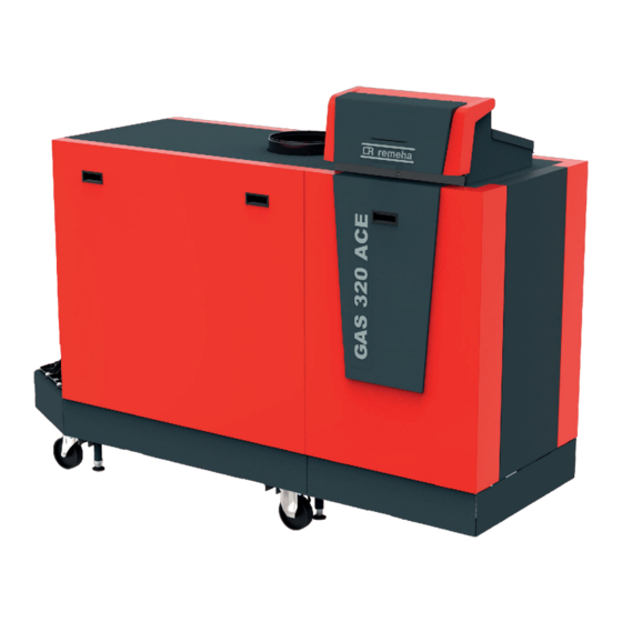
- Page 1 United Kingdom Installation and User Manual High-efficiency standing gas boiler Gas 320 Ace - Gas 620 Ace HMI T-control SCB-01 SCB-02...
- Page 2 Dear Customer, Thank you very much for buying this appliance. Please read through the manual carefully before using the product, and keep it in a safe place for later reference. In order to ensure continued safe and efficient operation we recommend that the product is serviced regularly. Our service and customer service organisation can assist with this.
-
Page 3: Table Of Contents
Contents Contents Safety ................... . 6 General safety instructions . - Page 4 CU-GH13 control unit parameters - Gas 320 Ace ....... . .
- Page 5 Contents 13 Appendix ..................92 13.1 ErP information .
-
Page 6: Safety
1 Safety Safety General safety instructions 1.1.1 For the installer Danger If you smell gas: 1. Do not use naked flames, do not smoke and do not operate electrical contacts or switches (doorbell, lighting, motor, lift etc.). 2. Shut off the gas supply. 3. -
Page 7: Recommendations
1 Safety Warning The condensate drain must not be modified or sealed. If a condensate neutralisation system is used, the system must be cleaned regularly in accordance with the instructions provided by the manufacturer. Caution Ensure that the boiler is regularly serviced. Contact a qualified installer or arrange a maintenance contract for the servicing of the boiler. -
Page 8: Liabilities
Instruction and warning labels must never be removed or covered and must be clearly legible throughout the entire service life of the boiler. Damaged or illegible instructions and warning stickers must be replaced immediately. Important Modifications to the boiler require the written approval of Remeha. Liabilities 1.3.1 Manufacturer's liability Our products are manufactured in compliance with the requirements of the various Directives applicable. -
Page 9: Symbols Used In The Manual
Boiler types The following boiler types are available: Tab.1 Boiler types Name Output Heat exchanger size Gas 320 Ace 285 279 kW 5 sections Gas 320 Ace 355 350 kW 6 sections Gas 320 Ace 430 425 kW 7 sections... -
Page 10: Main Components
9 Data plate 10 Siphon 11 Document holder AD-3001552-01 Fig.2 Gas 320 Ace - back 1 Flow connection 2 Second return connection 3 Return temperature sensor (when no second return is fitted) 4 Flue gas outlet connection 5 Return connection... -
Page 11: Introduction To The E-Smart Controls Platform
3 Description of the product Fig.4 Gas - air unit 1 Gas pressure measuring point 2 Gas supply tube 3 Gas - air connection piece 4 Pressure measurement point 5 Non-return valve 6 Gas filter 7 Gas valve 8 Air box 9 Fan 10 Venturi 11 Air supply hose... - Page 12 3 Description of the product Fig.7 Generic example R-Bus L-Bus S-Bus AD-3001366-02 Tab.2 Components in the example Item Description Function Control Unit: Control unit The control unit handles all basic functionality of the appli ance. Connection Board: Connection PCB The connection PCB provides easy access to all connectors of the control unit.
-
Page 13: Before Installation
B Boiler length (see table) 2 Support surface C Total length required (see table) A Support surface length (see table) Tab.4 Dimensions A / B / C (mm) Gas 320 Ace Gas 620 Ace A (mm) B (mm) C (mm) 1862... -
Page 14: Requirements For Water Connections
4 Before installation Gas 320 Ace Gas 620 Ace A (mm) B (mm) C (mm) 1862 2962 1000 1032 2172 3272 1150 1032 2172 3272 1300 1032 2172 3272 Requirements for water connections Before installation, check that the connections meet the set requirements. -
Page 15: Requirements On The Flue Gas Discharge System
Roof terminal and connection material Flue gas discharge via the roof. The air inlet is in the same pressure zone as the flue (e.g. a Remeha, combined with con concentric roof terminal). nection material from Muelink & Grol Remeha 350/350, in combi... - Page 16 4 Before installation Tab.7 Type of flue system: C Principle Description Recommended manufactur Connection in different pressure zones. Connection material and roof terminal: Closed unit. Separate air inlet and flue. Alukan Discharging into various pressure areas. Cox Geelen The air inlet and flue must not be placed on opposite walls. Muelink &...
-
Page 17: Material
4 Before installation 4.5.2 Material Use the string on the flue gas outlet material to check whether it is suitable for use on this appliance. Fig.10 Sample string 1 EN 14471 or EN 1856–1: The material is UKCA and CE approved according to this standard. -
Page 18: Length Of The Flue And Air Supply Pipes
L Length of the flue to roof terminal Flue gas outlet connection Tab.12 Maximum length (L) Diameter 250 mm Gas 320 Ace 285 50 m Gas 320 Ace 355 50 m Gas 320 Ace 430 50 m Gas 320 Ace 500... - Page 19 4 Before installation Fig.14 Room-sealed system Gas 320 Ace L Combined length of the flue and air supply channel to the roof terminal Flue gas outlet connection Air supply connection Tab.14 Maximum length (L) Diameter 250 mm 300 mm Gas 320 Ace 285...
-
Page 20: Additional Guidelines
4 Before installation Fig.17 Different pressure zones Gas 620 L Combined length of the flue and air supply channel Flue gas outlet connection Air supply connection Tab.17 Maximum length (L) Diameter 300 mm 350 mm 400 mm Gas 620 Ace 570 100 m 100 m 100 m... -
Page 21: Requirements For The Electrical Connections
4 Before installation on short term after installation. Check and clean the trap more often for these reasons. Requirements for the electrical connections Establish the electrical connections in accordance with all local and national current regulations and standards. Electrical connections must always be made with the power supply disconnected and only by qualified installers. - Page 22 4 Before installation Fig.19 Zone The schemes are divided in columns. All relevant connections and settings are grouped per column. AD-3001510-01 Fig.20 Heat demand Heat demand: The top row shows the heat demand (if applicable) for the zone. AD-3001506-01 Fig.21 Hydraulic connections Hydraulic connections: Only the essential parts are shown, parts to be connected to a PCB are numbered.
-
Page 23: How To Find The Desired Installation Example
4 Before installation Fig.26 Normal connector These connectors can be connected normally. AD-3001511-01 Fig.27 Combined connector These connectors combine two plugs into one connector. In the installation examples they appear with one highlighted part, which is to be used. AD-3001512-01 Fig.28 Connector to be bridged Row B shows all connectors to be bridged. - Page 24 4 Before installation Fig.31 Producer Tab.21 Producer Number Description Unknown / undefined producer Boiler with primary heating circuit (no pump) Boiler with primary heating circuit (internal pump) Boiler with primary heating circuit (external pump) Boiler with heating and domestic hot water (internal pump) Boiler with heating and domestic hot water (external pump) Boiler with primary and secondary heating circuit (internal pump)
-
Page 25: Symbols Used
4 Before installation Fig.33 Zones Tab.23 Zones Number Description Empty (no zone) Direct circuit Mixing circuit Swimming pool (direct) High temperature Fan convector (direct) Domestic hot water tank Domestic hot water tank (electrical) AD-3001530-02 Time program Process heat Domestic hot water tank (layered) Domestic hot water tank (internal) Underfloor heating (mixing) Heat interface unit... - Page 26 4 Before installation Tab.27 Hydraulic components Symbol Explanation Symbol Explanation Mixing valve or diverter valve Valve, electronically actuated Plate heat exchanger Low loss header Pump Safety group Tab.28 Sensors and contacts Symbol Explanation Symbol Explanation Outdoor temperature sensor Temperature sensor Safety thermostat Electrical cable Tab.29...
-
Page 27: Scb-02 Installation Example H-01-01-02-06-00-00-00
4 Before installation 4.8.4 SCB-02 Installation example H-01-01-02-06-00-00-00 Tab.32 Hydraulic scheme Producer Connection CH 1 / CircB 1 DHW 1 H 01 AD-3001435-01 AD-3001437-01 AD-3001484-01 AD-3001475-01 AD-3001432-01 AD-3001538-01 AD-3001486-01 (1) 01: Boiler with primary heating circuit (no pump) (2) 01: Direct connection (3) 02: Mixing circuit (4) 06: Domestic hot water tank (5) 00: Empty (no zone) - Page 28 4 Before installation Tab.34 Electrical connections to be bridged on CB-01 Producer Connection CH 1 / CircB 1 DHW 1 CB-01 (1) Bridge: These connectors must be bridged. Some bridges are already factory-fitted, some need to be fitted for this specific installation example.
-
Page 29: Scb-02 Installation Example H-01-01-01-06-00-00-00
4 Before installation 4.8.5 SCB-02 Installation example H-01-01-01-06-00-00-00 Tab.37 Hydraulic scheme Producer Connection CH 1 / CircB 1 DHW 1 H 01 AD-3001435-01 AD-3001437-01 AD-3001484-01 AD-3001475-01 AD-3001464-02 AD-3001538-01 AD-3001486-01 (1) 01: Boiler with primary heating circuit (no pump) (2) 01: Direct connection (3) 01: Direct circuit (4) 06: Domestic hot water tank (5) 00: Empty (no zone) -
Page 30: Installation
5 Installation Tab.39 Electrical connections to be bridged on CB-01 Producer Connection CH 1 / CircB 1 DHW 1 CB-01 (1) Bridge: These connectors must be bridged. Some bridges are already factory-fitted, some need to be fitted for this specific installation example. -
Page 31: Rotating The Control Box
5 Installation Fig.36 Place the boiler 1. Manoeuvre the boiler to the exact location. 2. Unscrew the levelling feet until they stand firmly on the floor. AD-3001416-02 Fig.37 Open the casing 3. Open the casing by lifting up the front panel and taking it off. AD-3001417-02 Fig.38 Level the boiler... - Page 32 5 Installation Fig.39 Open the control box 1. Undo the quarter turn screw. 2. Remove the cover. 3. Disconnect the earth wire from the cover. AD-3001868-01 Fig.40 Lift up the PCB mounting plate 4. Unscrew the two screws at the bottom of the PCB mounting plate. 5.
-
Page 33: Connecting The Heating Circuit
5 Installation Connecting the heating circuit For boiler Gas 620 Ace, apply the instructions to each boiler module. Fig.43 Connecting the heating circuit 1. Remove the dust caps from the flow and return connections. 2. Connect a safety valve to the flow connection. 3. -
Page 34: Connecting The Air Inlet And Flue Gas Outlet
5 Installation Connecting the air inlet and flue gas outlet Fig.46 Fit the flue gas outlet pipe to the 1. Fit the flue gas outlet pipe to the boiler. boiler 2. Fit the subsequent flue gas outlet pipes in accordance with the manufacturer's instructions. -
Page 35: The Cb-01 Connection Pcb
5 Installation 5.7.2 The CB-01 connection PCB Fig.49 Connection PCB CB-01 The CB-01 is placed in the control box. It provides easy access to all the standard connectors. S-Bus Pump 0-10 On/off Pump Tout AD-3000672-03 Connecting the system pump Fig.50 System pump 1. - Page 36 5 Installation Fig.53 Temperature regulation graph 1 Boiler on 2 Parameter CP010 3 Maximum flow temperature 4 Calculated value Tab.42 Temperature regulation Input signal (V) Temperature °C Description 0–1.5 0–15 Boiler off 1.5–1.8 15–18 Hysteresis 1.8–10 18–100 Desired temperature 0 - 10 V AD-0001156-03 0-10 Volt analogue output-based control The appliance can be controlled by a 0-10 Volt input signal.
- Page 37 5 Installation Room thermostat connector (On/off - OT) Fig.56 On/off - OT connector The On/off - OT connector can be used to connect a room thermostat. The connector supports the following types: On/off OpenTherm thermostat (for example, the iSense) OpenTherm Smart Power thermostat On/off thermostat It does not matter which wire is connected to which cable clamp.
-
Page 38: The Scb-01 Expansion Pcb
5 Installation 5.7.3 The SCB-01 expansion PCB Fig.59 SCB-01 PCB The SCB-01 has the following features: Two potential free contacts for status notifications 0–10 V output connection for a PWM system pump Expansion PCBs are automatically recognised by the control unit of the boiler. -
Page 39: The Scb-02 Expansion Pcb
5 Installation Caution If possible, use the pump modulation signal. This provides the most accurate pump control. If the automatic burner unit does not support pump modulation, the pump will behave as an on/off pump. 5.7.4 The SCB-02 expansion PCB Fig.62 SCB-02 PCB Status A... - Page 40 5 Installation Fig.64 Mixing valve connector Connect the mixing valve as follows: Earth N Neutral Open Close AD-4000015-03 Connecting the system pump Fig.65 System pump 1. Connect a system pump to the Pump terminals of the connector. Important The maximum power consumption is 300 VA. The function of the system pump can be changed using parameters PP015, PP016 and PP018.
-
Page 41: Connecting The Power Cable
5 Installation Connecting an outdoor temperature sensor An outdoor temperature sensor can be connected to the Tout connector. Always connect the sensor to the PCB that controls the zones. For example: when the zones are controlled by an SCB-02 or SCB-10, connect the sensor to that PCB. -
Page 42: Cable Routing In The Control Box Front Part
6 Preparation of commissioning Fig.72 Connecting the power cable 1. Undo the quarter turn screw. 2. Remove the cover. 3. Connect the power cable to the connector block. 4. Close the cover. 5. Tighten the quarter turn screw. AD-3001593-01 5.7.6 Cable routing in the control box front part Caution Make sure the cable routing matches the illustration when closing... -
Page 43: Filling The Siphon
6 Preparation of commissioning Fig.74 Filling and drain valve location 2. Fill the central heating system with clean water, using the filling and drain valve (½", fitted on the front section). 3. Check the water-side connections for tightness. 4. Power up the boiler. AD-3001559-01 6.1.2 Filling the siphon... -
Page 44: Control Panel Description
6 Preparation of commissioning Fig.77 Check the gas inlet pressure 1. Check the gas inlet pressure at measuring point P1. AD-3002127-01 Fig.78 Check and set the VPS dial 2. Check which pressure is set on the VPS dial. The VPS is located on the gas control valve. 7/8/9 3. -
Page 45: Description Of The Main Menu
6 Preparation of commissioning Fig.80 Icons on home screen 1 Tiles: the selected tile is highlighted 2 Date and time | Name of the screen (actual position in the menu) 3 Information about the selected tile 4 Icons indicating navigation level, operating mode, errors and other 22/02/2018 11:20 Home Screen information. -
Page 46: Commissioning
7 Commissioning Icon Description The solar calorifier is on and its heat level is displayed. CH operation is enabled. CH operation is disabled. DHW operation is enabled. DHW operation is disabled. The burner is on. The burner is off. Burner output level (1 to 5 bars, with each bar representing 20% output). The pump is running. -
Page 47: Gas Settings
Gas settings 7.2.1 Factory setting The factory setting of the boiler is for operation with the natural gas group G20 (H gas). Tab.48 Gas 320 Ace - Factory settings G20 (H-gas) Code Display text Description DP003 Abs. max fan Maximum fan speed on Domestic... -
Page 48: Fan Speeds For Breeam Compliance
For boiler Gas 620 Ace, apply the instructions to each boiler module. 1. Adjust the fan speed according to the tables below. The setting can be changed with a parameter setting. Tab.50 Gas 320 Ace - Adjustment for BREEAM with gas type G20 (H gas) Code Displayed text Description DP003 Abs. - Page 49 3. Compare the measured value with the checking values in the table. Tab.52 Checking/setting values for O at full load for G20 (H gas) Values at full load for G20 (H gas) Gas 320 Ace 285 4.3 – 4.8 – 9.3 Gas 320 Ace 355 4.3 – 4.8 – 9.3 Gas 320 Ace 430 4.3 –...
- Page 50 BREEAM with G20 (H gas) Values at full load for BREEAM with (1)(2) (3)(4) G20 (H gas) Gas 320 Ace 285 6.0 – 6.5 – 8.4 Gas 320 Ace 355 6.0 – 6.5 – 8.4 Gas 320 Ace 430 6.0 –...
- Page 51 3. Compare the measured value with the checking values in the table. Tab.54 Checking/setting values for O at low load for G20 (H gas) Values at low load for G20 (H gas) Gas 320 Ace 285 – 5.4 8.7 – 9.0 Gas 320 Ace 355 – 5.4 8.7 – 9.0 Gas 320 Ace 430 –...
-
Page 52: Final Instructions
7 Commissioning Values at low load for BREEAM with (1)(2) (3)(4) G20 (H gas) Gas 620 Ace 1150 – 7.2 7.7 – 8.0 Gas 620 Ace 1300 – 7.2 7.7 – 8.0 (1) Nominal value (2) These values are only applicable when the fan speeds have been set for BREEAM. -
Page 53: Saving The Commissioning Settings
8 Settings Fig.87 Example filled-in sticker 10. Fill in the following data on the sticker included, and attach it next to the data plate on the appliance. Adjusted for / Réglée pour / Parameters / Paramètres / The gas supply pressure; Ingesteld op / Eingestellt auf Parameter / Parametri / The flue type, if set to overpressure application;... -
Page 54: Searching The Parameters, Counters And Signals
8 Settings Fig.90 Second letter The second letter is the type. CP010 Parameter: Parameters Counter: Counters AD-3001376-01 Measurement: Signals Fig.91 Number The number is always three digits. In certain cases, the last of the three digits relates to a zone. CP010 AD-3001377-01 Searching the parameters, counters and signals... -
Page 55: Configuring The Installation At Installer Level
8 Settings Fig.95 Installer level 2.2. Use code: 0012. When the installer level is enabled or disabled, the status of ........00:12 the tile [ ] changes into On or Off............ -
Page 56: List Of Parameters
8 Settings List of parameters 8.4.1 CU-GH13 control unit parameters - Gas 320 Ace All tables show the factory setting for the parameters. Important The tables also list parameters that are only applicable if the boiler is combined with other equipment. - Page 57 8 Settings Code Display text Description Adjustment range Subme CP660 Icon display Choice icon to display this 0 = None CIRCA zone zone 1 = All 2 = Bedroom 3 = Livingroom 4 = Study 5 = Outdoor 6 = Kitchen 7 = Basement CP750 MaxZone...
- Page 58 8 Settings Code Display text Description Adjustment range Subme AP080 Frost min Outside temperature be -30 - 20 °C Outdoor out temp low which the antifreeze tempera protection is activated ture AP091 Outside Type of outside sensor 0 = Auto Outdoor Sens.
- Page 59 8 Settings Code Display text Description Adjustment range Subme CP640 OTH Logi Opentherm Logic level 0 = Open CIRCA cLev con contact of the zone 1 = Closed tact CP730 Zone Heat Selection of heat up speed 0 = Extra Slow CIRCA up speed of the zone...
- Page 60 8 Settings Tab.63 Factory settings at advanced installer level Code Display text Description Adjustment range Subme AP002 Manual Enable manual heat de 0 = Off Heat De mand function 1 = With setpoint fired ap mand pliance AP004 Hydr Valve Heat generator wait time 0 - 255 Sec Wait Time...
-
Page 61: Cu-Gh13 Control Unit Parameters - Gas 620 Ace
8 Settings Code Display text Description Adjustment range Subme GP010 GPS Check Gas Pressure Switch 0 = No check on/off 1 = Yes fired ap pliance GP017 Max power Maximum power percent 0 - 1000 kW 293. 353. 414. 496. 565. - Page 62 8 Settings Code Display text Description Adjustment range Subme 1000 1150 1300 CP080 User Room setpoint tempera 5 - 30 °C CIRCA CP081 T.Room Ac ture of the user zone activ CP082 tivity CP083 CP084 CP085 CP200 Manu Zo Manually setting the room 5 - 30 °C CIRCA neRoom...
- Page 63 8 Settings Code Display text Description Adjustment range Subme 1000 1150 1300 AP011 Service Hours powered to raise a 100 - 51000 Hours 1750 1750 1750 1750 1750 1750 hours mains service notification fired ap pliance AP013 Release Function of the release in 0 = Disabled function put contact...
- Page 64 8 Settings Code Display text Description Adjustment range Subme 1000 1150 1300 CP220 Zone HCZP Reduced footpoint of the 15 - 90 °C CIRCA Reduced temperature of heat curve of the circuit CP230 Zone Heat Heating curve temperature 0 - 4 CIRCA ing Curve gradient of the zone...
- Page 65 8 Settings Code Display text Description Adjustment range Subme 1000 1150 1300 GP009 Fan RPM Fan speed at appliance 900 - 5000 Rpm 2500 2500 1400 1400 1500 1600 Start start fired ap pliance Pneu matic PP015 CH Pump Central heating pump post 1 - 99 Min postrun time run time...
- Page 66 8 Settings Code Display text Description Adjustment range Subme 1000 1150 1300 CP290 ConfigZone Configuration of Zone 0 = Zone output CIRCA PumpOut Pump Output 1 = CH mode 2 = DHW mode 3 = Cooling mode 4 = Error report 5 = Burning 6 = Service flag 7 = System error...
-
Page 67: Maintenance
9 Maintenance Maintenance Maintenance regulations Important The boiler must be maintained by a qualified installer in accordance with local and national regulations. Important An annual inspection is mandatory. Perform the standard checking and maintenance procedures once a year. Perform the specific maintenance procedures if necessary. Important Adjust the frequency of inspection and service to the conditions of use. -
Page 68: Disposal And Recycling
The meaning of the code can be found in the various error code tables. Important The error code is needed to find the cause of the error quickly and correctly and for any support from Remeha. 10.1.1 Display of error codes... -
Page 69: Warning
10 Troubleshooting Fig.99 Error code display on HMI T-control 1 The display will show a corresponding code and message. 2 The status LED of the control panel will show: Continuous green = Normal operation Flashing green = Warning 22/02/2018 11:20 Home Screen .. -
Page 70: Blocking
10 Troubleshooting Code Display text Description Solution A.02.55 Inval or miss SerNR Invalid or missing device serial num Contact your supplier. A.03.17 Safety check Periodically safety check ongoing Safety check procedure active: No action 10.1.3 Blocking Tab.72 Blocking codes Code Display text Description Solution... - Page 71 10 Troubleshooting Code Display text Description Solution H.01.07 Max Delta TH-TR Maximum difference between heat Maximum difference between heat exchanger exchanger temperature and return and return temperature exceeded: temperature No flow or insufficient flow: Check the circulation (direction, pump, valves). Check the water pressure.
- Page 72 10 Troubleshooting Code Display text Description Solution H.02.00 Reset In Progress Reset In Progress Reset procedure active: No action H.02.02 Wait Config Number Waiting For Configuration Number Configuration error or unknown configuration number: Reset CN1 and CN2 H.02.03 Conf Error Configuration Error Configuration error or unknown configuration number:...
-
Page 73: Locking
10 Troubleshooting Code Display text Description Solution H.03.00 Parameter Error Safety parameters level 2, 3, 4 are Parameter error: security kernel not correct or missing Restart the boiler Replace the CU-GH H.03.01 CU to GVC data error No valid data from CU to GVC re Communication error with the CU-GH: ceived Restart the boiler... - Page 74 10 Troubleshooting Code Display text Description Solution E.00.08 THeat Ex Open Heat exchanger temperature sensor Heat exchanger temperature sensor open: is either removed or measures a Bad connection: check the wiring and connec temperature below range tors. Incorrectly fitted sensor: check that the sensor has been correctly fitted.
- Page 75 10 Troubleshooting Code Display text Description Solution E.02.04 Parameter Error Parameter Error Configuration error: Reset CN1 and CN2 The data plate for the CN1 and CN2 values. E.02.13 Blocking Input Blocking Input of the Control Unit Blocking input is active: from device external environment External cause: remove external cause Wrong parameter set: check the parameters...
- Page 76 10 Troubleshooting Code Display text Description Solution E.04.07 TFlow Sensor Deviation in flow sensor 1 and flow Flow temperature sensor deviation: sensor 2 detected Bad connection: check the connection Faulty sensor: replace the sensor E.04.08 Safety input Safety input is open Air pressure differential switch activated: Bad connection: check the wiring and connec...
-
Page 77: Error History
10 Troubleshooting Code Display text Description Solution E.04.13 Fan speed has exceeded normal op Fan fault: erating range Bad connection: check the wiring and connec tors. Fan operates when it should not be operating: check for excessive chimney draught Faulty fan: replace the fan E.04.15 FlueGas Pipe Blocked The flue gas pipe is blocked... -
Page 78: 11 User Instructions
11 User instructions Fig.100 Error details 3. Select the error code you want to investigate. The display shows an explanation of the error code and several ....22/02/2018 11:20 ... details of the appliance when the error occurred. Error Code: A.00.00 4. -
Page 79: Changing The Control Panel Settings
11 User instructions Menu Function Time programs heating Set and configure the time programs used when in operating mode Scheduling. Zone configuration Configure the settings of the zone circuit. Tab.75 Extended menu to configure a heating circuit Zone configuration Menu Function Short temperature change Change the room temperature temporarily, if required. -
Page 80: Reading The Installer's Name And Phone Number
11 User instructions 3. Select the timer program you want to modify: Schedule 1, Schedule 2 or Schedule 3. Activities scheduled for Monday are displayed. The last scheduled activity of a day is active until the first activity of the next day. At initial start-up, all weekdays have two standard activities;... -
Page 81: Cleaning The Casing
12 Technical specifications If the water temperature is higher than 10℃, the burner shuts down and the pump continues to run for a short time. To prevent the system and radiators freezing in frost-sensitive areas (e.g. a garage), a frost thermostat or, if feasible, an outdoor sensor can be connected to the boiler. -
Page 82: Bluetooth ® Wireless Technology
12 Technical specifications ® 12.1.3 Bluetooth wireless technology Fig.104 Logo This product is equipped with Bluetooth wireless technology. ® The Bluetooth word mark and logos are registered trademarks owned by Bluetooth SIG, Inc. and any use of such marks by BDR Thermea Group is under license. -
Page 83: Dimensions And Connections Gas 320 Ace
12 Technical specifications 22 Gas pressure switch (GPS) 23 Fan PWM signal 12.3 Dimensions and connections Gas 320 Ace Fig.106 Dimensions Gas 320 Ace AD-3001442-02 Gas 320 Ace Base length 1833 mm 2142 mm Flue gas outlet centre dimension 1635 mm... -
Page 84: Dimensions And Connections Gas 620 Ace
12 Technical specifications 12.4 Dimensions and connections Gas 620 Ace Fig.107 Dimensions Gas 620 Ace AD-3001443-02 Gas 620 Ace 1000 1150 1300 Base length 1833 mm 2142 mm Flue gas outlet centre dimension 1582 mm 1892 mm Total length 1862 mm 2172 mm Casing length 1490 mm... -
Page 85: Hydraulic Resistance
Gas 620 Ace 1000 9 sections: Gas 320 Ace 575 Gas 620 Ace 1150 10 sections: Gas 320 Ace 650 Gas 620 Ace 1300 12.6 Gas 320 Ace technical data Tab.80 General Gas 320 Ace Number of sections Nominal output 80/60 °C 51.1 64.8... - Page 86 12 Technical specifications Gas 320 Ace Full load central heating ef ) 70/50 °C 88.7 88.7 88.8 88.8 88.9 88.9 ficiency Full load central heating ef 50/30 °C 94.4 94.8 95.1 95.5 95.9 96.2 ficiency Min load central heating ef...
- Page 87 12 Technical specifications Gas 320 Ace Water flow at full load cen 80/60 °C 11.1 13.9 16.8 19.6 22.5 22.5 tral heating Water flow at full load cen 70/50 °C 11.3 14.1 17.1 19.9 22.9 25.9 tral heating Water flow at full load cen...
-
Page 88: Gas 620 Ace Technical Data
12 Technical specifications Tab.85 Technical parameters Gas 320 Ace Condensing boiler Low-temperature boiler B1 boiler Cogeneration space heater Combination heater Prated Rated heat output Useful heat output at nominal heat output 260.7 326.7 394.8 461.0 530.4 600.9 and high temperature operation Useful heat output at 30% of rated heat out... - Page 89 12 Technical specifications Gas 620 Ace 1000 1150 1300 Full load central heating ef ) 80/60 °C 98.0 98.1 98.2 98.3 98.4 98.5 ficiency Full load central heating ef ) 70/50 °C 98.5 98.5 98.6 98.6 98.7 98.7 ficiency Full load central heating ef 50/30 °C 104.8 105.2...
- Page 90 12 Technical specifications Gas 620 Ace 1000 1150 1300 Flue efficiency ) 80/60 °C Am 97.8 97.8 97.8 97.7 97.7 97.7 bient temperature 20 °C Flue losses ) 80/60 °C Am bient temperature 20 °C Tab.88 Central heating circuit data Gas 620 Ace 1000 1150...
- Page 91 12 Technical specifications Gas 620 Ace 1000 1150 1300 Fuse – CU-GH13 (AT) Fuse – CB-01 (AT) (1) Without pump (2) For a room-sealed system. Tab.90 Other data Gas 620 Ace 1000 1150 1300 Total weight with packaging Including control 1111 1179 1249...
-
Page 92: Ble Smart Antenna Technical Data
13 Appendix 13.1 ErP information 13.1.1 Product fiche Tab.93 Product fiche Remeha - Gas 320 Ace Seasonal space heating energy efficiency class (Prated or Psup) Rated heat output Seasonal space heating energy efficiency Annual energy consumption Sound power level L indoors Tab.94... - Page 93 13 Appendix 13.2.1 Declaration of conformity for wireless devices Fig.108 QR code All wireless communication devices comply with the standard type described in the EC declaration of conformity. They have been manufactured and commissioned in accordance with European and British directives.
- Page 94 13 Appendix 7734324 - v.07 - 21092022...
- Page 95 Original instructions - © Copyright All technical and technological information contained in these technical instructions, as well as any drawings and technical descriptions supplied, remain our property and shall not be multiplied without our prior consent in writing. Subject to alterations.
- Page 96 T +44 (0)330 678 0140 E technical@remeha.co.uk W www.remeha.co.uk Remeha Commercial UK Brooks House Coventry Road Warwick CV34 4LL 7734324 - v.07 - 21092022 7734324...
Need help?
Do you have a question about the Gas 320 Ace and is the answer not in the manual?
Questions and answers