REMEHA Gas 310 ECO Technical Information
Hide thumbs
Also See for Gas 310 ECO:
- User manual lines (20 pages) ,
- Assembly instructions manual (8 pages) ,
- Installation, user and service manual (36 pages)

Related Manuals for REMEHA Gas 310 ECO


Summary of Contents for REMEHA Gas 310 ECO
- Page 1 Technical Information Remeha Gas 310 ECO • High effi ciency condensing boiler with low NO emission • Heat outputs: 51 - 573 kW Supplied By www.heating spares.co Tel. 0161 620 6677...
-
Page 2: Table Of Contents
INHOUD Preface Installation instructions for ELECTRICAL installer Safety instructions General Symbols Electrical specifications 8.2.1 Mains voltage General description of boiler 8.2.2 Control unit 8.2.3 Power consumption Design 8.2.4 Fuse ratings Boiler version 8.2.5 Temperature control Operating principle 8.2.6 Low water level protection (flow and content) Technical data 8.2.7... - Page 3 Remeha Gas 310 ECO Installation instructions for gas installer 13.2.9 Maximum flue gas tempera- Gas connection ture (F) Gas pressures 13.2.10 Maximum temperature Gas/ air ratio control setting (G) 13.2.11 Modulation start point at dT (H) 10 Commissioning 13.2.12 Minimum water pressure (I) 10.1 Initial lighting...
-
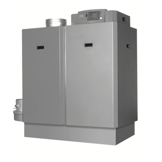
Page 4: Preface
Broag Ltd. for record purposes. fig. 01 Artist impression Gas 310 ECO 3D.AL.31H.000.S.01 Supplied By www.heating spares.co Tel. 0161 620 6677... -
Page 5: Safety Instructions 6 8.1 General
Boiler modifications and spare parts tions. The boiler must not be modified or non-Remeha spare parts fitted without the express written approval of Be aware of gas escapes Remeha. -
Page 6: General Description Of Boiler
The Gas 310 ECO frame is fitted with a set the heat output to suit the system load. The control is of casters to enable the assembled unit to be easily able to react to external “negative”... -
Page 7: Design
Remeha Gas 310 ECO DESIGN 3.1 Boiler version fig. 02 Cross-section Remeha Gas 310 ECO (Left hand boiler illustrated) 00.31H.79.00002 The service side of the boiler (with the heat exchanger inspection cover) is the front. Pressure gauge Air supply grille... -
Page 8: Operating Principle
3.2 Operating principle The boiler can be supplied, as an option with a Combustion air is drawn into the inlet connection from second (constant temperature) return connection. This the plant room (room ventilated version) or from outside additional connection enables the boiler to make full use via the eccentric flue system (room sealed) by an air of its condensing ability whilst accepting both fixed and supply fan. -
Page 9: Technical Data
Remeha Gas 310 ECO TECHNICAL DATA 4.1 Dimensions fig. 03 Elevation drawings (left-hand version shown) 04.31H.79.00002 É Flow connection NW 80, DIN 2576 Ê Return connection NW 80, DIN 2576 Ï Gas connection 2” BSP (F) Ò Condensate drain 1 ¼” nb plastic waste Ñ... -
Page 10: Technical Data
Weight dry Floor area Noise level at a distance of 1 m from the dB(A) boiler (average) Colour of casing 2002 (red); 9023 (grey) table 02 Technical data Remeha Gas 310 ECO Supplied By www.heating spares.co Tel. 0161 620 6677... -
Page 11: Quotation Specification
Remeha Gas 310 ECO 4.3 Quotation specification - Powder coated enamel steel casing BS; RAL colour: - Cast aluminium - sectional pre-mix gas fired fully 2002 (red); 9023 (grey) condensing, modulating floor standing boiler - Rigid steel box frame - Sectional heat exchanger manufactured from cast... -
Page 12: Accessories
Important!! When ordering a Remeha Gas 310 ECO, it is essential that the number of sections and whether a “left-hand” or “right-hand” connection version is required as well as the orientation of the instrument panel (short or front side). 4.5 Accessories - Modulating “OpenTherm”... -
Page 13: Efficiency Information
45°C Note: NCV = Hi, GCV = Hs APPLICATION DATA The Gas 310 ECO can be used on all new and refur- bishment projects in both single and multiple configu- rations. Conventional and room sealed flue system capability means that the boiler can be sited almost any- where within a building. -
Page 14: Installation Instructions For Heating Installer
Important: the rate of travel - Do not stand in front of the boiler! The Remeha Gas 310 ECO is a CE certified boiler and - Manoeuvre the boiler to required final position. must not be modified or installed in any way contrary to these “Installation and Maintenance Instructions”. - Page 15 1980 1980 Clearance of at least 800mm is required at the front fig. 06 Support area Remeha Gas 310 ECO (service side) of the boiler. However, we recommend a 00.31H.79.00005 clearance of 1 m. A clearance of at least 400mm above...
- Page 16 Horizontal pipework in the air supply system should 7.3.3 Connection options slope towards the supply opening and may require a The Remeha Gas 310 ECO is available in a room venti- drain point at the low point. lated and a room sealed version. If the room-sealed ver-...
-
Page 17: Single Boiler Conventional Flue
Gas 310 ECO, 8 sections, total length flue and air inlet nection to the Remeha Gas 310 ECO from ø 250 - ø each 32 m, each 2 bends 90°. -
Page 18: Single Boiler, Room Sealed Flue
fig. 09 Vertical terminal for room sealed operation Number of Ø D Ød1 Ød2 ØD 3 ØD 4 sections 2350 2350 2350 2500 2500 1060 2500 1160 2500 * Correct lengths for 11 and 19 sections; for the 9, 13, 15 and 17 sections, the pipe supplied must be shortened. This pipe is not suitable for the 7 section boiler. -
Page 19: Different Pressure Zones
UK this will usually have a pH of between 7 and 8). Pressurised installations with a boiler/ system content The Remeha Gas 310 ECO boilers are capable of oper- ratio of 1:10 or less should not require water treatment,... -
Page 20: Water Circulation
A safety valve should be fitted in accordance with BS traces of flux, debris, grease and metal swarf generated 6644. The flow pipe on the Remeha Gas 310 ECO during installation. Care to be taken with old systems to includes a fitting, which can be used for a safety valve, ensure any black metallic iron oxide sludge and other size 1½”... -
Page 21: Safety Valve
∆T of 11° are represented in table 08. The low loss header has to be sized for the maximal flow Q required. The Remeha Gas 310 ECO has no built-in pump. fig. 12 Low loss header > 500kW 00.W20.79.00040... - Page 22 Output up Flow Q D ø D square d interior inch inch 23,65 2 ½ 26,88 2 ½ 1041 37,63 1032 1213 1250 53,75 1233 1431 1500 64,50 1013 1351 1558 1550 66,65 1030 1373 1582 2000 86,00 1170 1560 1783 2275 97,83...
-
Page 23: Installation Instructions For Electrical
Remeha Gas 310 ECO INSTALLATION INSTRUCTIONS FOR ELECTRICAL INSTALLER 8.1 General The Remeha Gas 310 ECO is supplied as standard with electronic operating and flame ionisation safety controls with a specially designed microprocessor at the heart of the system. The boiler is pre-wired as shown in the wiring diagram in fig. -
Page 24: Temperature Control
13.2.10). When the fault is cor- 8.2.6 Low water level protection (flow and content) rected, the boiler can be restarted by using the reset- The Remeha Gas 310 ECO is equipped with low water key on the control panel. protection based on temperature differences (dT) between flow and return. -
Page 25: Connections
Remeha Gas 310 ECO 8.3 Connections The terminal strips and boiler connectors can be seen once the control box cover is removed. The left-hand terminal strip (X29) is used for 24-volt connections. The right-hand terminal strip (X27) is used for 230-volt con- nections. -
Page 26: Wiring Diagram
8.4 Wiring diagram fig. 17 Wiring diagram 04.31H.SC.00001 Supplied By www.heating spares.co Tel. 0161 620 6677... -
Page 27: Switch Sequence Diagram
Switch sequence diagram 04.31H.79.00003 8.6 Boiler control 8.6.1 Introduction The Remeha Gas 310 ECO can be controlled using one of the following methods: Note: when using on/off control the boiler will also modulate to maintain the flow temp set point (param-... -
Page 28: Modulating Controls General (Two Wire Control)
8.6.2 Modulating controls general (two wire control) To make full use of the boiler’s modulating feature, an ® ® OpenTherm or a rematic control can be connected. These controls will provide optimised time and weather compensation to achieve maximum efficiency and mini- mum boiler cycling whilst maintaining design condition ®... -
Page 29: High/ Low Control (2 X No Volt Switched Pairs)
Remeha Gas 310 ECO Output 8.6.5 High/ low control (2 x no volt switched pairs) Description signal The heat output is controlled between part load (50%, adjustable) and full load, by means of a two-stage 0 volts Boiler off controller, terminal connections X29-9 and X29-10.low 0.5 volts... -
Page 30: Options/ Accessories
(parameter J). 8.9.1 Boiler or System pump control The Remeha Gas 310 ECO has a facility to provide a 8.8.2 Gas valve leak proving system (VPS) power supply (230V Max 2 amps) to run or control an The gas valve leak proving system checks and operates external boiler or system pump. -
Page 31: Installation Instructions For Gas Installer
Remeha Gas 310 ECO INSTALLATION INSTRUCTIONS FOR GAS INSTALLER 9.1 Gas connection 9.3 Gas/ air ratio control The Gas 310 is suitable for use with natural gas only. The boiler has a pressure differential gas/ air ratio The gas connection is at the top of the boiler (see fig. - Page 32 17.e Run the boiler at part load (forced mode ‘low’) by pressing the m and [-] keys simultaneously for 2 seconds. The letter l will now appear on the display. When part load is reached, measure dP gas at 17.f measuring point P on the underside of the gas valve multiblock and at measuring point PL on the venturi and compare to the value in table...
-
Page 33: Shutdown
Set the boiler controls to the required values. Send the commissioning reports to Broag. Note: The Remeha Gas 210 ECO is supplied with a number of factory default settings that should be correct for most installations. If other setting values are required: see sections 13.1. -
Page 34: Control And Safety Equipment
- free access 2. Service level - access with service code by qualified personnel 3. Factory level - access by PC with factory code (Remeha only) fig. 24 Instrument panel 00.31H.79.00010 (fig. 2) t window displaying: The functions of the keys and read-out windows (a to h) are explained below. -
Page 35: Led Indicators
Remeha Gas 310 ECO 11.1.2 LED indicators This is. Parameters can be changed in this mode. The instrument panel has 4 indicating LED’s with the fol- By pressing the [+]- and [-]-keys simultaneously, the lowing functions: boiler will return to operating mode. -
Page 36: Operating Mode
OPERATING MODE 12.1 Operating mode (x [[) During normal operation the code-display shows the status (position in cycle) of the boiler, with the t -dis- play indicating the actual flow temperature. The digits or letters in the code-display have the follow- ing meaning: Code Description... -
Page 37: Control Strategy C
Remeha Gas 310 ECO Switch-on temperature for central heating demanded value operation (°) Requested (and permitted by boiler con- 00 - )0 (=100%) trol) output (%) is displayed, irrespective of demanded value boiler control setting. 10 - )0 (=100) (actual value) -
Page 38: Counter Mode (1, , And .)
Code Description Shut-off code (see table 22) Operating code, at shut-off intervention (section 12.1) Flow temperature, at shut-off intervention Return temperature, at shut-off intervention Flue gas temperature, at shut-off intervention Boiler block temperature, at shut-off intervention Time from shut-off intervention (with PC software only) 7 + 8 Ionisation level (analog), at shut-off intervention Operating hours (hundred thousands and ten thousands) -
Page 39: Setting Mode
Remeha Gas 310 ECO SETTING MODE 13.1 User level setting mode (X [[) Setting mode is used to change various settings to suit individual requirements. The required code is selected by pressing the m key until ! appears in the code window. Select the required code with the s key. Now press the [+] key to increase a setting or the [-] key to decrease a setting. -
Page 40: Pump Run On Time (@)
Example: boiler control 41 indicates that the boiler is 13.1.2 Pump run on time (@) Pump run on time can be adjusted (Please refer to controlled by means of a 0 -10 volt signal modulated on installation contractor). the basis of flow temperature (x = 4). Heat demand is - Press the m-key until the digit ! (with dot) appears in on (y = 1). - Page 41 Remeha Gas 310 ECO Code Description Setting range Factory setting Minimum fan speed (hundreds), see sec- 5 sections: 1500 rpm 06 - 60 (x 100 rpm) tion 13.2.1 6 sections: 1600 rpm 7 sections: 1100 rpm Minimum fan speed (units), see section...
-
Page 42: Minimum Fan Speed ($ And 5)
The percentage 'high' position depends on the set maxi- mum central heating speed. Important!! Only make changes after con- sulting Remeha sales support department. 13.2.2 Maximum fan speed (^ and 7) Parameter ^, Adjustable between 10 and 60 (x100 rpm) and parameter 7 adjustable between 0 and 100 (x 1 rpm). -
Page 43: Modulation Start Point At Dt (H)
Remeha Gas 310 ECO Important!! If the factory setting is reduced, a Examples: corresponding reduction in flow setpoint will be required - Factory setting is 0: the analog output will be in %. otherwise the min flow rate may be effected. -
Page 44: Fault-Finding
FAULT-FINDING 14.1 General Operating hours (thousands and hun- If the boiler does not start up, check the following: dreds) - Is a 230 V supply present; Operating hours (tens and units) - Is there a heat demand; - Has the boiler control (parameter 3) been set cor- Fan speed at failure (thousands and rectly (see section 13.1.3). - Page 45 Remeha Gas 310 ECO Failure Description Cause/check points - Burner glows as a result of a high CO percentage. Flame simulation, (flame - Check the combined ignition/ionisation electrode (gap should be 3 to detected when control is in the 4 mm apart).
- Page 46 - Maximum thermostat (= external protection), connected to terminals X29-1 and X29-2 on the terminal strip, has tripped or wire bridge has Locked input open been removed - Fuse F3 on automatic burner unit is defective. Gas valve multiblock protection Gas valve multiblock defective or not connected Check: Flow temperature too high - Flow...
- Page 47 Remeha Gas 310 ECO - Flue gas recirculation. Check flue gas discharge system for installa- Lack of ionisation during opera- tion faults and heat exchanger for possible leaks tion (after 4 restarts during 1 - Insufficient air flow due to blockage heat demand) - Check the boiler settings.
-
Page 48: Inspection And Maintenance Instructions
15.1 General If ionisation level < 3 µA dc or not present, check: The Remeha Gas 310 ECO has been designed to need - Is flame shape stable and colour as described in minimum maintenance, but to ensure optimum efficiency commissioning instructions. -
Page 49: Inspection Of Air Box And Dirt Trap
Remeha Gas 310 ECO All general cleaning should be carried out with 15.4.3 Cleaning the venturi compressed air, a soft brush or damp cloth to avoid Use compressed air or a synthetic brush to clean venturi damaging components. (Solvents must not be –... -
Page 50: Cleaning The Burner Assembly
15.4.5 Cleaning the heat exchanger 15.4.7 Cleaning the condensate collector Release the retaining nuts from heat exchanger cover Clean the condensate collector by removing the inspec- plate, remove plate, be careful not to damage the gas- tion cover (next to the flue gas discharge) and then rins- ket, store safely. -
Page 51: Cleaning The Inspection Glass
Remeha Gas 310 ECO 15.4.9 Cleaning/Replacing the Ignition/Ionisation Re-assemble boiler in reverse order, check front plate electrode gasket and insulation piece, replace if required. Also Remove safety bracket from the heat exchanger then check the gasket on fan and on gas valve, replace if remove the two retaining screws on the electrode necessary. -
Page 52: Exploded View And Spare Parts List
15.5 Exploded view and spare parts list fig. 37 Exploded view Supplied By www.heating spares.co Tel. 0161 620 6677... - Page 53 Remeha Gas 310 ECO Pos. nr. Part description Pos. nr. Part description Teflon tape O-ring Ø 183 Loctite Fan (for 7, 8, 9 sections) PVC glue Nut M8 Cleaning tool Sealing plate fan/ mixing elbow (for 7, 8, 9 sections)
- Page 54 Pos. nr. Part description Pos. nr. Part description Inspection cover Plug À" Bolt M6 x 16 Sealing cable Ø 10 Return blind pipe Flue gas sensor jacket Second return distribution pipe Straight connecting flange Flue gas sensor Straight connecting flange Cover plate controller Condensate collector Front panel...
-
Page 55: Appendices
Remeha Gas 310 ECO APPENDICES 16.1 Control menu fig. 38 Control menu flow chart Supplied By www.heating spares.co Tel. 0161 620 6677... -
Page 56: Shut-Off Codes
16.2 Shut-off codes Code Description Cause/Check - Air supply or flue gas discharge for Insufficient air transport during pre-ventilation. blockages/ installation faults The boiler is locked after 5 restarts (6 starts) with code 08 - Air pressure differential switch and (see section 14.4). - Page 57 Remeha Gas 310 ECO - Check the connecting cable of the hydraulic pressure sensor $6 Hydraulic pressure sensor open - The hydraulic pressure sensor is defective or not connected Maximum flue gas temperature has been exceeded. The - The set maximum flue gas tempera- boiler shuts down for 150 seconds, followed by a restart.
- Page 58 Supplied By www.heating spares.co Tel. 0161 620 6677...
- Page 59 Broag Ltd. Remeha House Molly Millars Lane RG41 2QP WOKINGHAM, Berks. Tel: +44 118 9783434 © Copyright Fax: +44 118 9786977 All technical and technological information contained in these technical instructions, as Internet: uk.remeha.com well as any drawings and technical descriptions furnisched by us remain our property and may not be multiplied without our prior consent in writing.
Need help?
Do you have a question about the Gas 310 ECO and is the answer not in the manual?
Questions and answers