
Subscribe to Our Youtube Channel
Related Manuals for REMEHA Gas 320 Ace


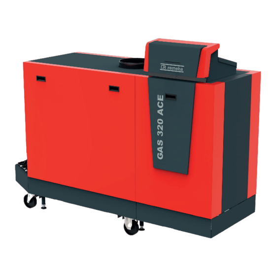
Summary of Contents for REMEHA Gas 320 Ace
- Page 1 United Kingdom Service Manual High-efficiency standing gas boiler Gas 320 Ace - Gas 620 Ace HMI T-control SCB-01 SCB-02...
- Page 2 Dear Customer, Thank you very much for buying this appliance. Please read through the manual carefully before using the product, and keep it in a safe place for later reference. In order to ensure continued safe and efficient operation we recommend that the product is serviced regularly. Our service and customer service organisation can assist with this.
-
Page 3: Table Of Contents
CU-GH13 control unit parameters - Gas 320 Ace ....... . . - Page 4 Contents 6.4.1 CU-GH13 control unit counters ............49 6.4.2 SCB-01 expansion PCB counters .
-
Page 5: About This Manual
Boiler types The following boiler types are available: Tab.1 Boiler types Name Output Heat exchanger size Gas 320 Ace 285 279 kW 5 sections Gas 320 Ace 355 350 kW 6 sections Gas 320 Ace 430 425 kW 7 sections... -
Page 6: Main Components
9 Data plate 10 Siphon 11 Document holder AD-3001552-01 Fig.2 Gas 320 Ace - back 1 Flow connection 2 Second return connection 3 Return temperature sensor (when no second return is fitted) 4 Flue gas outlet connection 5 Return connection... -
Page 7: Introduction To The E-Smart Controls Platform
2 Description of the product Fig.4 Gas - air unit 1 Gas pressure measuring point 2 Gas supply tube 3 Gas - air connection piece 4 Pressure measurement point 5 Non-return valve 6 Gas filter 7 Gas valve 8 Air box 9 Fan 10 Venturi 11 Air supply hose... - Page 8 2 Description of the product Fig.7 Generic example R-Bus L-Bus S-Bus AD-3001366-02 Tab.2 Components in the example Item Description Function Control Unit: Control unit The control unit handles all basic functionality of the appli ance. Connection Board: Connection PCB The connection PCB provides easy access to all connectors of the control unit.
-
Page 9: Use Of The Control Panel
3 Use of the control panel Use of the control panel Control panel components Fig.8 Control panel components 1 Rotary knob to select a tile, menu or setting 2 Confirm button to confirm the selection 3 Back button Short button press: Return to the previous level or previous menu Long button press: Return to home screen 4 Menu button... -
Page 10: Description Of The Icons In The Display
3 Use of the control panel Tab.5 Available menus for the installer Description Icon Disable installer access Installation Setup Commissioning Menu Advanced Service Menu Error History Bluetooth System Settings Version Information 3.3.1 Description of the icons in the display Tab.6 Icons Icon Description... -
Page 11: Installer Instructions
4 Installer instructions Icon Description Icon Description Bluetooth enabled and connected (icon is non-trans Bluetooth enabled and disconnected (icon is trans parent). parent). Heating enabled. Cooling enabled. Heating/cooling enabled. Heating/cooling disabled. Tab.8 Icons - Zones Icon Description All zones (groups) icon. Living room icon. -
Page 12: Establishing A Bluetooth Connection
4 Installer instructions Fig.13 Installer level 1.2. Use code: 0012. The tile [ ] shows that the installer access is On, and the ........00:12 icon in the top right of the display changes into ............ -
Page 13: Chimney Sweep Menu
4 Installer instructions 2. Follow the instructions on the display. Important The appliance might take a few minutes during certain steps while commissioning. Do not shut off the appliance or try to bypass steps, unless stated otherwise on the display. 3. -
Page 14: Saving The Commissioning Settings
4 Installer instructions 2. Select the test Medium power. Fig.17 Full load test A Change load test mode B Medium power The full load test starts. The selected load test mode is shown in the 11:20 ....... menu and the icon appears in the top right of the screen. -
Page 15: Changing The Control Panel Settings
4 Installer instructions Icon Zone or function Description Gas fired appliance Gas boiler Shower time function Activate the shower time function Tab.12 Configuring a zone or function of CU-GH08 or SCB-02 Parameters, counters, signals Description Parameters Set the parameters at installer level Counters Read the counters at installer level Signals... -
Page 16: Setting The Parameters
4 Installer instructions 4.5.3 Setting the parameters You can change the settings of the control unit and the connected expansion boards, sensors etc. to configure the installation. The factory settings support the most common heating systems. The user or the installer can optimise the parameters as required. -
Page 17: Increasing The Domestic Hot Water Temperature Temporarily
4 Installer instructions 4.5.5 Increasing the domestic hot water temperature temporarily You can temporary increase the hot water temperature when the time program is active with the reduced temperature setpoint. Use this to deviate from the time program or testing of the hot water production. >... -
Page 18: Viewing Production And Software Information
4 Installer instructions 5. Select Counters or Signals to read out a counter or signal. Fig.21 Parameters, counters, signals Parameters Counters Signals 11:20 ....: ....B List of settings or values ................. -
Page 19: Carrying Out An Auto Detect
4 Installer instructions Important All custom settings will be erased when the configuration numbers are reset. Depending on the appliance, there can be factory set parameters to enable certain accessories. Use the saved commissioning settings to restore these settings after the reset. If no commissioning settings were saved, write down custom settings before resetting. -
Page 20: Advanced Settings
4.8.3 Changing the ΔT setting The ΔT is factory set to 25 °C. It can be increased by a Remeha service technician. Contact Remeha for more information. Important When increasing the ΔT, the control unit limits the flow temperature to a maximum of 80 °C. -
Page 21: Cascade Control
4 Installer instructions Important The settings for these temperatures must follow the screed layer's recommendations. Activation of this function via the parameter CP470 forces the permanent display of the screed drying function and deactivates all other regulator functions. When the screed drying function is active on one circuit, all other circuits and the domestic hot water circuit continue to run. -
Page 22: Installation Examples
5 Installation examples Fig.26 Traditional cascade control 1 First boiler starts running when system temperature is 3°C below management set point. 2 After 4 minutes the second boiler starts running if ΔT< 6K and the system temperature is still more than 3°C below set point. 3 After 8 minutes the third boiler starts running if ΔT<... -
Page 23: Connecting Diagrams
5 Installation examples Connecting diagrams 5.2.1 How to use the installation examples In this chapter, a few installation examples are given. Each example provides a quick overview of a simple hydraulic set-up, together with the connections that have to be made and the parameters to be set on the PCB's. -
Page 24: How To Find The Desired Installation Example
5 Installation examples Fig.34 Parameters to be set Parameters to be set: The parameters are separated per PCB, and must be set on that specific PCB. AD-3001509-01 Fig.35 Parameter list Parameter list: The parameters from the table above are repeated in this list to show their display text, navigation paths, and settings. - Page 25 5 Installation examples Fig.41 Producer Tab.17 Producer Number Description Unknown / undefined producer Boiler with primary heating circuit (no pump) Boiler with primary heating circuit (internal pump) Boiler with primary heating circuit (external pump) Boiler with heating and domestic hot water (internal pump) Boiler with heating and domestic hot water (external pump) Boiler with primary and secondary heating circuit (internal pump)
-
Page 26: Symbols Used
5 Installation examples Fig.43 Zones Tab.19 Zones Number Description Empty (no zone) Direct circuit Mixing circuit Swimming pool (direct) High temperature Fan convector (direct) Domestic hot water tank Domestic hot water tank (electrical) AD-3001530-02 Time program Process heat Domestic hot water tank (layered) Domestic hot water tank (internal) Underfloor heating (mixing) Heat interface unit... - Page 27 5 Installation examples Tab.23 Hydraulic components Symbol Explanation Symbol Explanation Mixing valve or diverter valve Valve, electronically actuated Plate heat exchanger Low loss header Pump Safety group Tab.24 Sensors and contacts Symbol Explanation Symbol Explanation Outdoor temperature sensor Temperature sensor Safety thermostat Electrical cable Tab.25...
-
Page 28: Scb-02 Installation Example H-01-01-02-06-00-00-00
5 Installation examples 5.2.4 SCB-02 Installation example H-01-01-02-06-00-00-00 Tab.28 Hydraulic scheme Producer Connection CH 1 / CircB 1 DHW 1 H 01 AD-3001435-01 AD-3001437-01 AD-3001484-01 AD-3001475-01 AD-3001432-01 AD-3001538-01 AD-3001486-01 (1) 01: Boiler with primary heating circuit (no pump) (2) 01: Direct connection (3) 02: Mixing circuit (4) 06: Domestic hot water tank (5) 00: Empty (no zone) - Page 29 5 Installation examples Tab.30 Electrical connections to be bridged on CB-01 Producer Connection CH 1 / CircB 1 DHW 1 CB-01 (1) Bridge: These connectors must be bridged. Some bridges are already factory-fitted, some need to be fitted for this specific installation example.
-
Page 30: Scb-02 Installation Example H-01-01-01-06-00-00-00
5 Installation examples 5.2.5 SCB-02 Installation example H-01-01-01-06-00-00-00 Tab.33 Hydraulic scheme Producer Connection CH 1 / CircB 1 DHW 1 H 01 AD-3001435-01 AD-3001437-01 AD-3001484-01 AD-3001475-01 AD-3001464-02 AD-3001538-01 AD-3001486-01 (1) 01: Boiler with primary heating circuit (no pump) (2) 01: Direct connection (3) 01: Direct circuit (4) 06: Domestic hot water tank (5) 00: Empty (no zone) -
Page 31: Settings
6 Settings Tab.35 Electrical connections to be bridged on CB-01 Producer Connection CH 1 / CircB 1 DHW 1 CB-01 (1) Bridge: These connectors must be bridged. Some bridges are already factory-fitted, some need to be fitted for this specific installation example. -
Page 32: Searching The Parameters, Counters And Signals
AC001 AD-3001917-01 List of parameters 6.3.1 CU-GH13 control unit parameters - Gas 320 Ace All tables show the factory setting for the parameters. Important The tables also list parameters that are only applicable if the boiler is combined with other equipment. - Page 33 6 Settings Tab.39 Factory settings at basic installer level Code Display text Description Adjustment range Subme AP016 CH function Enable central heating 0 = Off heat demand processing 1 = On fired ap pliance AP017 DHW func Enable domestic hot water 0 = Off tion on heat demand processing...
- Page 34 6 Settings Tab.41 Factory settings at installer level Code Display text Description Adjustment range Subme AP001 BL function BL input function selection 1 = Full blocking 2 = Partial blocking fired ap 3 = User reset lock pliance AP006 Min. water Appliance will report low 0 - 6 bar pressure...
- Page 35 6 Settings Code Display text Description Adjustment range Subme CP020 Zone Func Functionality of the zone 0 = Disable CIRCA tion 1 = Direct 2 = Mixing Circuit 3 = Swimming pool 4 = High Tempera ture 5 = Fan Convector 6 = DHW tank 7 = Electrical DHW 8 = Time Program...
- Page 36 6 Settings Code Display text Description Adjustment range Subme CP780 Control Selection of the control 0 = Automatic CIRCA strategy strategy for the zone 1 = Room Temp. based 2 = Outdoor Temp. based 3 = Outdoor & room based EP014 SCB func.
- Page 37 6 Settings Code Display text Description Adjustment range Subme AP063 Max CH Maximum central heating 20 - 90 °C Produc flow setpoint flow temperature setpoint er Ge neric fired ap pliance AP102 Boiler Pump Configuration of the boiler 0 = No function pump as zone pump or 1 = Yes...
-
Page 38: Cu-Gh13 Control Unit Parameters - Gas 620 Ace
6 Settings Code Display text Description Adjustment range Subme GP042 Fan RPM Maximum fan speed 0 - 65535 Rpm 5700 5800 3700 4000 4500 4300 Pneu matic GP050 Power Min Minimum power in kilo 0 - 300 kW Watt for RT2012 calcula fired ap... - Page 39 6 Settings Code Display text Description Adjustment range Subme 1000 1150 1300 CP550 Zone, fire Fire Place mode is active 0 = Off CIRCA place 1 = On CP570 ZoneTime Time Program of the zone 0 = Schedule 1 CIRCA Prog Select selected by the user 1 = Schedule 2...
- Page 40 6 Settings Code Display text Description Adjustment range Subme 1000 1150 1300 AP073 Summer Outdoor temperature: up 15 - 30.5 °C Outdoor Winter per limit for heating tempera ture AP079 Building In Inertia of the building used 0 - 10 Outdoor ertia for heat up speed...
- Page 41 6 Settings Code Display text Description Adjustment range Subme 1000 1150 1300 CP480 ScreedStart Setting of the start temper 20 - 50 °C CIRCA Temp ature of the screed drying program of the zone CP490 ScreedStop Setting of the stop temper 20 - 50 °C CIRCA Temp...
- Page 42 6 Settings Tab.48 Navigation for advanced installer level Level Menu path Advanced installer > Installation Setup > CU-GH13 > Submenu > Parameters, counters, signals > Parameters > Advanced (1) See the column "Submenu" in the following table for the correct navigation. The parameters are grouped in specific functionalities. Tab.49 Factory settings at advanced installer level Code...
-
Page 43: Scb-01 Expansion Pcb Parameters
6 Settings Code Display text Description Adjustment range Subme 1000 1150 1300 DP020 Postrun Post run time of the DHW 0 - 99 Sec pump/3 way valve after fired ap pump/3wv DHW production pliance DP140 DHW load DHW load type (0 : Combi, 0 = Combi type 1 : Solo) -
Page 44: Scb-02 Expansion Pcb Parameters
6 Settings Tab.51 Factory settings at installer level Code Display text Description Adjustment range Submenu Default setting EP018 Status relay func. Status relay function 0 = No Action Status infor No Ac 1 = Alarm mation tion 2 = Alarm Inverted 3 = Generator on 4 = Generator off 5 = Reserved... - Page 45 6 Settings Tab.53 Factory settings at basic installer level Code Display text Description Adjustment range Submenu Default setting AP074 Force summer The heating is stopped. Hot water is 0 = Off Outdoor mode maintained. Force Summer Mode 1 = On temperature CP010 Tflow setpoint...
- Page 46 6 Settings Tab.54 Navigation for installer level Level Menu path Installer > Installation Setup > SCB-02 > Submenu > Parameters, counters, signals > Parameters > General (1) See the column "Submenu" in the following table for the correct navigation. The parameters are grouped in specific functionalities. Tab.55 Factory settings at installer level Code...
- Page 47 6 Settings Code Display text Description Adjustment range Submenu Default setting CP220 Zone HCZP Re Reduced footpoint of the temperature 15 - 90 °C DHW 1 15 °C CP221 duced of heat curve of the circuit CIRCB 1 15 °C CP230 Zone Heating Heating curve temperature gradient...
- Page 48 6 Settings Code Display text Description Adjustment range Submenu Default setting CP630 StartdayAntileg Startday of the function antilegionella 1 = Monday DHW 1 Satur CP631 zone of the zone 2 = Tuesday CIRCB 1 3 = Wednesday Satur 4 = Thursday 5 = Friday 6 = Saturday 7 = Sunday...
-
Page 49: List Of Measured Values
6 Settings Tab.56 Navigation for advanced installer level Level Menu path Advanced installer > Installation Setup > SCB-02 > Submenu > Parameters, counters, signals > Parameters > Advanced (1) See the column "Submenu" in the following table for the correct navigation. The parameters are grouped in specific functionalities. Tab.57 Factory settings at advanced installer level Code... - Page 50 6 Settings Code Display text Description Range Submenu AC003 Hours since service Number of hours since the previous 0 - 131070Hours Gas fired ap servicing of the appliance pliance AC004 Starts since service Number of heat generator starts since 0 - 4294967295 Gas fired ap...
-
Page 51: Scb-01 Expansion Pcb Counters
6 Settings Tab.63 Counters at advanced installer level Code Display text Description Range Submenu PC001 ChCtrTotalPower Total power consumption used by Cen 0 - 4294967295kW Gas fired ap Cons. tral Heating pliance 6.4.2 SCB-01 expansion PCB counters Tab.64 Navigation for basic installer level Level Menu path Basic installer... - Page 52 6 Settings Code Display text Description Range Submenu AM019 Water pressure Water pressure of the primary circuit. 0 - 10bar Gas fired ap pliance AM027 Outside tempera Instantaneous outside temperature -70 - 70°C Outdoor tem ture perature Gas fired ap pliance AM028 0to10Vinput...
- Page 53 6 Settings Code Display text Description Range Submenu CM160 Zone Mod HeatDe Presense of modulating heat demand 0 = No CIRCA mand per zone 1 = Yes CM200 ZoneCurrentHeat Displaying current operating mode of the 0 = Standby CIRCA Mode zone 1 = Heating 2 = Cooling...
-
Page 54: Scb-01 Expansion Pcb Signals
6 Settings Code Display text Description Range Submenu GM015 Vps Switch Valve Proving System switch open / 0 = Open Gas fired ap closed 1 = Closed pliance 2 = Off PM003 ChTflowAverage Actual average flow temperature -25 - 125°C Gas fired ap... - Page 55 6 Settings Tab.75 AM014 - Sub status Code Display text Explanation Standby The appliance waits for a process or an action. AntiCycling The appliance waits to restart, because there were too many consecutive heat demands (anti-short cycle). WaitingForStartCond. The appliance waits for the temperature to meet the start conditions. CloseExtGasValve An external gas valve is opened, when this option is connected to the ap...
-
Page 56: Maintenance
7 Maintenance Maintenance Maintenance regulations Important The boiler must be maintained by a qualified installer in accordance with local and national regulations. Important An annual inspection is mandatory. Perform the standard checking and maintenance procedures once a year. Perform the specific maintenance procedures if necessary. Important Adjust the frequency of inspection and service to the conditions of use. -
Page 57: Standard Inspection And Maintenance Operations
7 Maintenance Standard inspection and maintenance operations For a service, always perform the following standard inspection and maintenance operations. 7.3.1 Preparation Carry out the following steps before commencing inspection and maintenance activities: 1. Set the boiler to full load until the return temperature is around 65°C, to dry the heat exchanger on the flue gas side. - Page 58 7 Maintenance Tab.76 Checking/setting values for O at full load for G20 (H gas) Values at full load for G20 (H gas) Gas 320 Ace 285 4.3 – 4.8 – 9.3 Gas 320 Ace 355 4.3 – 4.8 – 9.3 Gas 320 Ace 430 4.3 –...
- Page 59 3. Compare the measured value with the checking values in the table. Tab.78 Checking/setting values for O at low load for G20 (H gas) Values at low load for G20 (H gas) Gas 320 Ace 285 – 5.4 8.7 – 9.0 Gas 320 Ace 355 – 5.4 8.7 – 9.0 Gas 320 Ace 430 –...
- Page 60 7 Maintenance Values at low load for G20 (H gas) Gas 320 Ace 575 – 5.4 8.7 – 9.0 Gas 320 Ace 650 – 5.4 8.7 – 9.0 Gas 620 Ace 570 – 5.4 8.7 – 9.0 Gas 620 Ace 710 –...
-
Page 61: Checking The Water Quality
7 Maintenance Fig.56 Adjusting screw B 5. Use the adjustment screw B to set the percentage of O for the gas type being used to the nominal value. Increasing the gas flow, will decrease O and increase CO . The direction in which the adjusting screw must be turned to increase or decrease the gas flow is indicated on the gas control valve. -
Page 62: Checking And Cleaning The Air Supply Hose
3. Check the gas inlet pressure at measuring point 2 on the gas control valve. 4. Compare the measured values with the values in the table. Tab.80 Minimum gas inlet pressure values at gas control valve measuring point 2 Gas 320 Ace Gas 620 Ace Minimum value (mbar) 1000 1150 1300 5. -
Page 63: Checking The Air Box
7 Maintenance 7.3.6 Checking the air box Fig.61 Air box 1. Check the air box for soiling. 2. Clean the dirty air box using a vacuum cleaner. Do this from the connection opening for the air supply hose. Important If the air box is dirty, the following components must also be dismantled and blown clean: Non-return valve Venturi... -
Page 64: Checking The Gas Leakage Monitoring (Vps)
7 Maintenance Fig.63 Negative (-) side of the air pressure 10. Remove the syringe hose from the + side of the air pressure differential switch differential switch and reconnect the original hose. 11. Disconnect the silicon hose from the - side (P2) of the air pressure differential switch. -
Page 65: Checking The Minimum Gas Pressure Switch (Gps)
7 Maintenance Fig.66 Checking the VPS for leaks 7. Take a T piece and connect it as follows: 7.1. Connect one end of the T piece to the hose from measuring point 3. 7.2. Connect one end of the T piece to a large plastic syringe. 7.3. -
Page 66: Specific Maintenance Work
AD-3001409-01 Fig.72 Check the value 7. Compare the measured value with the minimum value in the table. Tab.81 Minimum gas pressure switch value Gas 320 Ace Gas 620 Ace Minimum value (mbar) X mbar 1000 AD-3001410-01... -
Page 67: Cleaning The Fan, Non-Return Valve And Venturi
7 Maintenance 7.4.1 Cleaning the fan, non-return valve and venturi Fig.73 Disassembling the fan unit 1. Push back the safety slides on both sides of the power plug to unlock 2. Remove the electrical connections from the fan. 3. Unscrew the bolts from the extension piece under the fan. Support the gas control valve, using a block of wood for example. -
Page 68: Cleaning The Gas Filter - 5-9 Sections Boiler
7 Maintenance Fig.76 Replacing the ionisation/ignition 1. Unscrew the two screws on the middle top casing. electrode 2. Remove the middle top casing. 3. Remove the plug of the electrode from the ignition transformer. Important The ignition cable is fixed to the electrode and may not be removed. -
Page 69: Cleaning The Burner
7 Maintenance Fig.80 Inspecting and cleaning the gas 4. Inspect the gas filter. filter 4.1. Replace the gas filter if necessary. 4.2. Clean the gas filter without the use of liquids (shake it or carefully blow it clean) if it does not need to be replaced. 5. -
Page 70: Cleaning The Heat Exchanger
7 Maintenance 7.4.6 Cleaning the heat exchanger Fig.85 Removing the inspection hatch 1. Unscrew the nuts from the inspection hatch on the heat exchanger. 2. Carefully remove the inspection hatch, the insulation cloth and the silicon insulation cord from the heat exchanger. Caution The insulation cloth may stick to the heat exchanger. -
Page 71: Cleaning The Siphon
7 Maintenance 7.4.8 Cleaning the siphon Fig.88 Cleaning the siphon 1. Remove the siphon. 2. Clean the siphon with water. 3. Put the siphon back in place. 4. Turn the clip counterclockwise to access the sealing cap. 5. Remove the sealing cap from the condensate collector. AD-3001605-01 Fig.89 Filling the siphon... -
Page 72: Finalising Work
The meaning of the code can be found in the various error code tables. Important The error code is needed to find the cause of the error quickly and correctly and for any support from Remeha. 7734325 - v.07 - 22092022... -
Page 73: Display Of Error Codes
8 Troubleshooting 8.1.1 Display of error codes When an error occurs in the installation, the control panel will show the following: Fig.93 Error code display on HMI T-control 1 The display will show a corresponding code and message. 2 The status LED of the control panel will show: Continuous green = Normal operation Flashing green = Warning 22/02/2018 11:20... -
Page 74: Blocking
8 Troubleshooting Code Display text Description Solution A.02.49 Failed Init Node Failed Initialising Node SCB not found: Carry out an auto-detect A.02.55 Inval or miss SerNR Invalid or missing device serial num Contact your supplier. A.03.17 Safety check Periodically safety check ongoing Safety check procedure active: No action 8.1.3... - Page 75 8 Troubleshooting Code Display text Description Solution H.01.07 Max Delta TH-TR Maximum difference between heat Maximum difference between heat exchanger exchanger temperature and return and return temperature exceeded: temperature No flow or insufficient flow: Check the circulation (direction, pump, valves). Check the water pressure.
- Page 76 8 Troubleshooting Code Display text Description Solution H.02.00 Reset In Progress Reset In Progress Reset procedure active: No action H.02.02 Wait Config Number Waiting For Configuration Number Configuration error or unknown configuration number: Reset CN1 and CN2 H.02.03 Conf Error Configuration Error Configuration error or unknown configuration number:...
-
Page 77: Locking
8 Troubleshooting Code Display text Description Solution H.03.00 Parameter Error Safety parameters level 2, 3, 4 are Parameter error: security kernel not correct or missing Restart the boiler Replace the CU-GH H.03.01 CU to GVC data error No valid data from CU to GVC re Communication error with the CU-GH: ceived Restart the boiler... - Page 78 8 Troubleshooting Code Display text Description Solution E.00.08 THeat Ex Open Heat exchanger temperature sensor Heat exchanger temperature sensor open: is either removed or measures a Bad connection: check the wiring and connec temperature below range tors. Incorrectly fitted sensor: check that the sensor has been correctly fitted.
- Page 79 8 Troubleshooting Code Display text Description Solution E.02.04 Parameter Error Parameter Error Configuration error: Reset CN1 and CN2 The data plate for the CN1 and CN2 values. E.02.13 Blocking Input Blocking Input of the Control Unit Blocking input is active: from device external environment External cause: remove external cause Wrong parameter set: check the parameters...
- Page 80 8 Troubleshooting Code Display text Description Solution E.04.07 TFlow Sensor Deviation in flow sensor 1 and flow Flow temperature sensor deviation: sensor 2 detected Bad connection: check the connection Faulty sensor: replace the sensor E.04.08 Safety input Safety input is open Air pressure differential switch activated: Bad connection: check the wiring and connec...
-
Page 81: Error History
8 Troubleshooting Code Display text Description Solution E.04.13 Fan speed has exceeded normal op Fan fault: erating range Bad connection: check the wiring and connec tors. Fan operates when it should not be operating: check for excessive chimney draught Faulty fan: replace the fan E.04.15 FlueGas Pipe Blocked The flue gas pipe is blocked... -
Page 82: Technical Specifications
9 Technical specifications Fig.94 Error details 3. Select the error code you want to investigate. The display shows an explanation of the error code and several ....22/02/2018 11:20 ... details of the appliance when the error occurred. Error Code: A.00.00 4. -
Page 83: Bluetooth ® Wireless Technology
Only replace defective or worn boiler parts with original parts or recommended parts. Send the part to be replaced to the Remeha Quality Control department if the relevant part is covered by the guarantee (see the General Terms of Sale and Delivery). -
Page 84: Exploded Views
10 Spare parts 10.2 Exploded views Fig.97 Gas 320/620 Ace - Casing 1009 1008 1001 1009 1019 1006 1008 1017 1020 1003 1007 1002 1005 1017 1029 1024 1030 1031 1004 1027 1028 1012 1036 1023 1051 1025 1006 1021 1032 1036 1022... - Page 85 10 Spare parts Fig.98 Gas 320/620 Ace - Heat exchanger and burner 2054 2013 2014 2053 2015 2097 2047 2019 2016 2009 2001 2055 2101 2022 2017 2009 2018 2021 2017 2019 2002 2009 2003 2025 2019 2009 2008 2017 2019 2010 2017...
- Page 86 10 Spare parts Fig.99 Gas 320/620 Ace - Gas / air 3104 3017 3052 3057 3018 3015 3004 3046 3031 3033 3041 3042 3002 3023 3054 3035 3039 3023 3016 3009 3003 3016 3037 3007 3047 3049 3006 3005 3040 3025 3025 3051...
- Page 87 10 Spare parts Fig.100 Gas 320/620 Ace - Control box 4037 4028 4020 4015 4011 4025 4031 4030 4010 4024 4009 4039 4026 4027 4038 4034 4040 4032 4008 4029 4022 4004 4008 4021 4039 4013 4014 4003 4035 4040 4012 4036 4016...
- Page 88 10 Spare parts Fig.101 Gas 620 Ace 5006 5001 5005 5002 5003 5006 5001 5005 5002 5004 5004 5004 5007 5007 AD-4800023-02 7734325 - v.07 - 22092022...
-
Page 89: Parts List
10 Spare parts 10.3 Parts list Tab.86 Gas 320/620 Ace - Casing Item Part number Description 1001 S103092 Top cover 5-7 sections 1001 S103091 Top cover 8-10 sections 1002 S103095 Top cover front (outer part) 1003 7749834 LED lighting 1003 7665256 Magnets 1004... - Page 90 10 Spare parts Item Part number Description 1042 S103136 Condensate collector 8-10 sections 1043 S103302 Condensate collector strip 6 sections 1044 S62713 O-ring ø 20 x 2.5 mm (10 pcs.) 1045 S103243 Levelling foot (2 pcs.) 1046 S103143 Syphon connection 1047 S103261 Sealing ring 45 x 34 x 3 mm (10 pcs.)
- Page 91 10 Spare parts Item Part number Description 2028 S57724 Inspection hatch heat exchanger 9 sections 2028 S103148 Inspection hatch heat exchanger 10 sections 2029 S100549 Stud M8 x 20 mm (25 pcs.) 2030 S100556 Nut M8 (25 pcs.) 2031 S57738 2nd return water pipe blind 5 sections 2031 S57739...
- Page 92 10 Spare parts Item Part number Description 3001 S103277 Gas control valve 7-9 sections 3002 S57770 Fan 5-6 sections 3003 S103150 Fan 7-10 sections 3004 S100347 Burner 5 sections 3004 S103077 Burner 6 sections 3004 S100329 Burner 7 sections 3004 S100330 Burner 8 sections 3004...
- Page 93 10 Spare parts Item Part number Description 3054 S103330 Gasket non return valve (5 pcs.) 3055 S103356 Pressure test nipple 1/8" (2 pcs.) 3056 S103357 Adapter 1/8" M5 (2 pcs.) incl. loctite 3057 S100490 Burner insulation repair set 3100 7745411 Valve proving system (VPS) 5-9 sections 3100 7745414...
- Page 94 10 Spare parts Tab.90 Gas 620 Ace Item Part number Description 5001 S103128 Junction for air inlet or flue gas outlet 5002 S103119 Flue gas pipe ø 250 mm l= 890 mm 5003 S103318 Flue gas pipe support 5004 S103311 Cover set 5-7 sections 5004 S103312...
- Page 95 Original instructions - © Copyright All technical and technological information contained in these technical instructions, as well as any drawings and technical descriptions supplied, remain our property and shall not be multiplied without our prior consent in writing. Subject to alterations.
- Page 96 T +44 (0)330 678 0140 E technical@remeha.co.uk W www.remeha.co.uk Remeha Commercial UK Brooks House Coventry Road Warwick CV34 4LL 7734325 - v.07 - 22092022 7734325...
Need help?
Do you have a question about the Gas 320 Ace and is the answer not in the manual?
Questions and answers