Emerson Rosemount 8600 Series Quick Start Manual
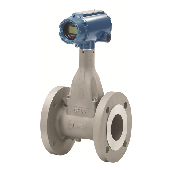
Vortex flowmeter
Hide thumbs
Also See for Rosemount 8600 Series:
- Reference manual (130 pages) ,
- Quick start manual (24 pages)

Related Manuals for Emerson Rosemount 8600 Series


Summary of Contents for Emerson Rosemount 8600 Series
- Page 1 Quick Start Guide 00825-0100-4860, Rev. EA September 2016 ™ Rosemount 8600 Series Vortex Flowmeter...
-
Page 2: Table Of Contents
September 2016 Quick Start Guide 1.0 About this guide This guide provides basic guidelines for the Rosemount ™ 8600D Series Vortex Flowmeter. It does not provide instructions for detailed configuration, diagnostics, maintenance, service, troubleshooting, Explosion-proof, Flameproof, or Intrinsically Safe (I.S.) installations. Refer to the Rosemount 8600D Reference Manual for more instruction. -
Page 3: Mount The Flowmeter
Quick Start Guide September 2016 2.0 Mount the flowmeter Design process piping so the meter body will remain full, with no entrapped air. The vortex flowmeter can be installed in any orientation without affecting accuracy. However, the following are guidelines for certain installations. 2.1 Vertical mounting If the vortex flowmeter will be installed in a vertical orientation: Install upward or downward flow for gas or steam. - Page 4 September 2016 Quick Start Guide 2.3 High temperature mounting The maximum temperature for integral electronics is dependent on the ambient temperature where the flowmeter is installed. The electronics must not exceed 185 °F (85 °C). Figure 3 shows combinations of ambient and process temperatures needed to maintain a housing temperature of less than 185 °F (85 °C).
- Page 5 Quick Start Guide September 2016 Figure 4. Improper Installation 2.5 Upstream/downstream requirements The Rosemount 8600D Flowmeter may be installed with a minimum of ten straight pipe diameters (D) upstream and five straight pipe diameters (D) downstream by following the K-factor corrections as described in the 8800 Installation Effects Technical Data Sheet (00816-0100-3250).
- Page 6 September 2016 Quick Start Guide 2.7 Flanged-style installation Figure 6. Flanged-Style Flowmeter Installation A. Installation bolts and nuts (supplied by customer) B. Gaskets (supplied by customer) C. Flow Note The required bolt load for sealing the gasket joint is affected by several factors, including operating pressure, gasket material, width, and condition.
- Page 7 Quick Start Guide September 2016 Figure 7. Remote Electronics Installation Note: Consult factory for SST installation. A. Meter body J. Electronics housing B. Support tube K. Ground connection C. Sensor cable nut L. Housing base screw D. Nut M. Housing adapter E.
- Page 8 September 2016 Quick Start Guide 7. Remove one of the four housing base screws. 8. Attach and securely tighten the coaxial cable nut to the connection on the electronics housing. 9. Attach the coaxial cable ground wire to the housing via the housing base ground screw.
-
Page 9: Consider Housing Rotation
Quick Start Guide September 2016 3.0 Consider housing rotation The entire electronics housing may be rotated in 90° increments for easy viewing. Use the following steps to change the housing orientation: 1. Loosen the four housing rotation set screws at the base of the electronics housing with a ”... -
Page 10: Set Jumpers And Switches
September 2016 Quick Start Guide 4.0 Set jumpers and switches Adjust jumpers to desired settings. 4.1 HART If alarm and security jumpers are not installed, the flowmeter will operate normally with the default alarm condition alarm high and the security off. Figure 8. -
Page 11: Connect Wiring And Power Up
Quick Start Guide September 2016 5.0 Connect wiring and power up 5.1 Conduit installation Prevent condensation in any conduit from flowing into the housing by mounting the flowmeter at a high point in the conduit run. If the flowmeter is mounted at a low point in the conduit run, the terminal compartment could fill with fluid. - Page 12 September 2016 Quick Start Guide Note Straight threads require a minimum of three wraps of tape to obtain a tight seal. 5. If applicable, install wiring with a drip loop. Arrange the drip loop so the bottom is lower than the conduit connections and the flowmeter housing. Figure 11.
-
Page 13: Verify Configuration
Quick Start Guide September 2016 1. Verify the cover jam screw is completely threaded into the housing. 2. Install the transmitter housing cover and verify that the cover is tight against the housing. 3. Using an M4 hex wrench, loosen the jam screw until it contacts the transmitter cover. - Page 14 September 2016 Quick Start Guide Table 1. Field Communicator Fast Key Sequence for Rosemount 8600D Function HART Fast Key Function HART Fast Key Alarm Jumpers 1, 4, 2, 1, 3 Meter Body Number 1, 4, 1, 5 Analog Output 1, 4, 2, 1 Minimum Span 1, 3, 8, 3 Auto Adjust Filter...
- Page 15 Quick Start Guide September 2016 Table 1. Field Communicator Fast Key Sequence for Rosemount 8600D Function HART Fast Key Function HART Fast Key Mass Flow 1, 1, 4, 2 Velocity Meas Base 1, 1, 4, 3, 3 Mass Flow Units 1, 1, 4, 2, 2 Volumetric Flow 1, 1, 4, 1...
-
Page 16: Product Certifications
September 2016 Quick Start Guide 7.0 Product certifications 7.1 Approved manufacturing locations Emerson Process Management Flow Technologies Company, Ltd - Nanjing, Jiangsu Province, P.R. China 7.2 Flameproof enclosure Ex d protection type in accordance with IEC 60079-1, EN 60079-1 Transmitters with Flameproof enclosure type protection shall only be opened ... - Page 17 Quick Start Guide September 2016 8.0 Hazardous Location Certifications 8.1 North American Certifications Canadian Standards Association (CSA) E6 Explosion proof–Intrinsically Safe for Class I, Division 1, Groups B, C, and D; Ex d[ia] IIC T6 Gb / Class I, Zone 1, AEx d[ia] IIC T6 Gb Dust-ignition proof for Class II/III, Division 1, Groups E, F, and G;...
- Page 18 September 2016 Quick Start Guide Type 'n' certification IEC 60079-0: 2011 Edition: 6.0 IEC 60079-11: 2011-06 Edition: 6.0 IEC 60079-15: 2010 Edition: 4 N7 Certification No. IECEx BAS 12.0054X Ex nA ic IIC T5 Gc (-40 °C ≤ Ta ≤ +70 °C) Maximum Working Voltage = 42Vdc Special Conditions for Safe Use (X): 1.
- Page 19 Special Conditions for Safe Use (X): 1. The maximum allowable length of the interconnecting cable between transmitter and sensor is 152m. The cable shall also be provided by Rosemount Inc., or by Emerson Process Management Co., Ltd., or by Emerson Process Management Flow Technologies., Ltd.
- Page 20 September 2016 Quick Start Guide I3 Certification No. GYJ12.1239X Ex ia IIC T4 Ga (-60 °C ≤ Ta ≤ +70 °C) Ui = 30 Vdc Ii = 185 mA Pi = 1.0 W Ci = 0uF Li= 0.97mH Special Conditions for Safe Use (X): 1.
- Page 21 Quick Start Guide September 2016 Special Conditions for Safe Use (X): 1. The maximum allowable length of the interconnecting cable between transmitter and sensor is 152m. The cable shall also be provided by the manufacturer. 2. Suitable heat-resisting cables rated at least +80 °C shall be used when the temperature of the cable entry around exceed +60 °C.
- Page 22 September 2016 Quick Start Guide 3. When the equipment is installed, particular precautions must be taken to ensure taking into account the effect of process fluid temperature, that the ambient temperature of the electrical housing of the equipment meets the marked protection type temperature range.
- Page 23 Quick Start Guide September 2016 3. Units marked with “Warning: Electrostatic Charging Hazard” may use non-conductive paint thicker than 0.2 mm. Precautions shall be taken to avoid ignition due to electrostatic charge on the enclosure. 8.5 EurAsian Conformity (EAC) This section addresses compliance with the requirements of technical regulations of the Customs Union.
- Page 24 September 2016 Quick Start Guide Input intrinsically safe parameters: Output signal Intrinsically safe 4-20mA/HART parameters Pulse Ui,* V Ii,* mA Pi,* W Li, uH Ci, nF * Applicable values Ui, Ii are limited by the maximum input power Pi. * It is not allowed to apply max values of Ui, Ii at the same time. Special conditions for safe use (X): 1.
- Page 25 Quick Start Guide September 2016 Figure 12. Rosemount 8600D Declaration of Conformity...
- Page 26 September 2016 Quick Start Guide...
- Page 28 Standard Terms and Conditions of Sale can be found at Emerson Process Management www.Emerson.com/en-us/pages/Terms-of-Use.aspx Emerson FZE P.O. Box 17033, The Emerson logo is a trademark and service mark of Emerson Jebel Ali Free Zone - South 2 Electric Co. Dubai, United Arab Emirates Rosemount and Rosemount logotype are trademarks of Emerson Process Management.
Need help?
Do you have a question about the Rosemount 8600 Series and is the answer not in the manual?
Questions and answers