
Related Manuals for Emerson Rosemount 8782


Summary of Contents for Emerson Rosemount 8782
- Page 1 Reference Manual 00809-0100-8782, Rev AA November 2019 ® Rosemount 8782 Slurry Magnetic Flow Meter Transmitter with HART Protocol...
-
Page 3: Table Of Contents
Reference Manual Contents 00809-0100-8782 November 2019 Contents Chapter 1 Hazard messages......................7 1.1 Safety messages..........................8 Chapter 2 Introduction.........................11 2.1 System description......................... 11 2.2 Product recycling/disposal......................12 Chapter 3 Sensor Installation....................... 13 3.1 Handling and Lifting Safety......................13 3.2 Location and Position........................14 3.3 Sensor Installation.......................... - Page 4 12.6 Sensor troubleshooting......................140 12.7 Installed sensor tests........................142 12.8 Uninstalled sensor tests......................144 12.9 Technical support and service.....................146 Appendix A Product Specifications....................149 A.1 Rosemount 8782 Slurry Magnetic Flow Meter Platform Specifications......... 149 ® Rosemount 8782 Slurry Magnetic Flow Meter Transmitter with HART Protocol...
- Page 5 Reference Manual Contents 00809-0100-8782 November 2019 A.2 Transmitter specifications......................153 A.3 MS Sensor Specifications......................160 A.4 8785 Reference Calibration Standard................... 165 Appendix B Product Certifications....................167 Appendix C Wiring Diagrams......................169 C.1 Wiring sensor to transmitter......................169 ™ C.2 775 Smart Wireless THUM Adapter wiring diagrams..............170 C.3 Field Communicator wiring diagrams...................172 Reference Manual...
- Page 6 Contents Reference Manual November 2019 00809-0100-8782 ® Rosemount 8782 Slurry Magnetic Flow Meter Transmitter with HART Protocol...
-
Page 7: Chapter 1 Hazard Messages
Reference Manual Hazard messages 00809-0100-8782 November 2019 Hazard messages This document uses the following criteria for hazard messages based on ANSI standards Z535.6-2011 (R2017). DANGER Serious injury or death will occur if a hazardous situation is not avoided. WARNING Serious injury or death could occur if a hazardous situation is not avoided. CAUTION Minor or moderate injury will or could occur if a hazardous situation is not avoided. -
Page 8: Safety Messages
The products described in this document are NOT designed for nuclear-qualified applications. Using non-nuclear qualified products in applications that require nuclear-qualified hardware or products may cause inaccurate readings. For information on Emerson nuclear-qualified products, contact your local sales representative. ®... - Page 9 Reference Manual Hazard messages 00809-0100-8782 November 2019 WARNING Explosion hazards. Failure to follow these instructions could cause an explosion, resulting in death or serious injury. • If installed in explosive atmospheres (hazardous areas, classified areas, or an “Ex” environment), it must be assured that the device certification and installation techniques are suitable for that particular environment.
- Page 10 Hazard messages Reference Manual November 2019 00809-0100-8782 protectors must be used. If frequent removal is anticipated, take precautions to protect the liner ends. Short spool pieces attached to the sensor ends are often used for protection. • Correct flange bolt tightening is crucial for proper sensor operation and life. All bolts must be tightened in the proper sequence to the stated torque specifications.
-
Page 11: Chapter 2 Introduction
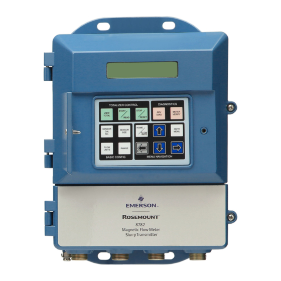
Reference Manual Introduction 00809-0100-8782 November 2019 Introduction System description The flowmeter consists of a sensor and a transmitter. The sensor is installed in-line with the process piping; the transmitter is remotely mounted away from the sensor. Figure 2-1: 8782 transmitter Figure 2-2: MS sensor The flow sensor contains two magnetic coils located on opposite sides of the sensor. -
Page 12: Product Recycling/Disposal
Introduction Reference Manual November 2019 00809-0100-8782 Figure 2-3: Sensor cross section A. Electrode B. Coils Product recycling/disposal Recycling of equipment and packaging should be taken into consideration and disposed of in accordance with local and national legislation/regulations. ® Rosemount 8782 Slurry Magnetic Flow Meter Transmitter with HART Protocol... -
Page 13: Chapter 3 Sensor Installation
Reference Manual Sensor Installation 00809-0100-8782 November 2019 Sensor Installation This chapter provides instructions for handling and installing the flow sensor with a remotely mounted transmitter. Related information Remote Transmitter Installation Handling and Lifting Safety CAUTION To reduce the risk of personal injury or damage to equipment, follow all lifting and handling instructions. -
Page 14: Location And Position
Sensor Installation Reference Manual November 2019 00809-0100-8782 3.1.1 Lifting lugs CAUTION If provided, use the lifting lugs on each flange to handle the flow meter when it is transported and lowered into place at the installation site. If lifting lugs are not provided, the flow meter must be supported with a lifting sling on each side of the housing. - Page 15 Reference Manual Sensor Installation 00809-0100-8782 November 2019 Figure 3-2: Upstream and downstream straight pipe diameters A. Five pipe diameters (upstream) B. Two pipe diameters (downstream) C. Flow direction Installations with reduced upstream and downstream straight runs are possible. In reduced straight run installations, the meter may not meet accuracy specifications. Reported flow rates will still be highly repeatable.
- Page 16 Sensor Installation Reference Manual November 2019 00809-0100-8782 Figure 3-4: Sensor orientation A. Flow direction 3.2.5 Electrode orientation The electrodes in the sensor are properly oriented when the two measurement electrodes are in the 3 and 9 o’clock positions or within 45 degrees from the horizontal, as shown on the left side of Figure 3-5.
-
Page 17: Sensor Installation
Reference Manual Sensor Installation 00809-0100-8782 November 2019 The sensor may require a specific orientation to comply with Hazardous Area T-code rating. Refer to the appropriate reference manual for any potential restrictions. Sensor Installation 3.3.1 Flanged sensors Gaskets The sensor requires a gasket at each process connection. The gasket material must be compatible with the process fluid and operating conditions. - Page 18 Sensor Installation Reference Manual November 2019 00809-0100-8782 Bolts Note Do not bolt one side at a time. Tighten both sides simultaneously. Example: 1. Snug upstream 2. Snug downstream 3. Tighten upstream 4. Tighten downstream Do not snug and tighten the upstream side and then snug and tighten the downstream side.
- Page 19 Reference Manual Sensor Installation 00809-0100-8782 November 2019 Table 3-1: Lining material Fluoropolymer liners Other liners T - PTFE P - Polyurethane K - PFA+ N - Neoprene L - Linatex (Natural Rubber) D - Adiprene Table 3-2: Suggested flange bolt torque values for Rosemount MS (ASME) sensors Size Line size Fluoropolymer liners...
-
Page 20: Process Reference Connection
Sensor Installation Reference Manual November 2019 00809-0100-8782 Table 3-3: Suggested flange bolt torque values for Rosemount MS sensors with fluoropolymer liners (EN 1092-1) (continued) Size Line size Fluoropolymer liners (in Newton-meters) code PN 10 PN 16 PN 25 PN 40 8 inch (200 mm) 10 inch (250 mm) 12 inch (300 mm) - Page 21 Reference Manual Sensor Installation 00809-0100-8782 November 2019 Table 3-5: Process reference options Type of pipe Grounding Grounding rings Reference Lining protectors straps electrode Conductive Figure 3-8 Figure 3-9 Figure 3-11 Figure 3-9 unlined pipe Conductive lined Insufficient Figure 3-9 Figure 3-8 Figure 3-9 pipe grounding...
- Page 22 Sensor Installation Reference Manual November 2019 00809-0100-8782 Figure 3-9: Grounding with grounding rings or lining protectors in conductive pipe A. Grounding rings or lining protectors Figure 3-10: Grounding with grounding rings or lining protectors in non-conductive pipe A. Grounding rings or lining protectors ®...
- Page 23 Reference Manual Sensor Installation 00809-0100-8782 November 2019 Figure 3-11: Grounding with reference electrode in conductive unlined pipe Figure 3-12: Grounding for line sizes 10-in. and larger Reference Manual...
- Page 24 Sensor Installation Reference Manual November 2019 00809-0100-8782 ® Rosemount 8782 Slurry Magnetic Flow Meter Transmitter with HART Protocol...
-
Page 25: Remote Transmitter Installation
Reference Manual Remote Transmitter Installation 00809-0100-8782 November 2019 Remote Transmitter Installation This chapter provides instructions for installing and wiring a remotely mounted transmitter. Related information Sensor Installation Pre-installation Before installing the transmitter, there are several pre-installation steps that should be completed to make the installation process easier: •... - Page 26 The mounting site for the transmitter should provide enough room for secure mounting, easy access to conduit entries, full opening of the transmitter covers, and easy readability of the Local Operator Interface (LOI) screen (if equipped). Figure 4-1: Rosemount 8782 Dimensional Drawing (229) (89)
- Page 27 Reference Manual Remote Transmitter Installation 00809-0100-8782 November 2019 Electrical considerations Before making any electrical connections to the transmitter, consider national, local, and plant electrical installation requirements. Be sure to have the proper power supply, conduit, and other accessories necessary to comply with these standards. The transmitter requires external power.
-
Page 28: Transmitter Symbols
Remote Transmitter Installation Reference Manual November 2019 00809-0100-8782 Transmitter symbols Caution symbol — check product documentation for details Protective conductor (grounding) terminal Mounting Wall mount transmitters are shipped with mounting hardware for use on a 2 inch (50 mm) pipe or flat surface. Figure 4-2: Mounting bracket A. -
Page 29: Wiring
Reference Manual Remote Transmitter Installation 00809-0100-8782 November 2019 4.3.2 Surface mounting Attach the transmitter to the mounting location using customer supplied mounting screws. The installation of the transmitter shall be rated for four (4) times the weight of the transmitter or 44lbs (20kgs). Wiring 4.4.1 Conduit entries and connections... - Page 30 Remote Transmitter Installation Reference Manual November 2019 00809-0100-8782 Figure 4-3: Best practice conduit preparation A. Safety ground B. Power C. Coil D. Output E. Electrode 4.4.3 Sensor to transmitter wiring Remote cable kits can be ordered directly using the kit numbers shown in Table 4-4 Table 4-5.
- Page 31 Reference Manual Remote Transmitter Installation 00809-0100-8782 November 2019 Table 4-4: Component cable kits - standard temperature (-20°C to 75°C) (continued) Cable kit # Description Individual cable Alpha p/n 08732-0065-0003 (feet) Kit, component cables, Std temp Coil 2442C (includes Coil and I.S. Electrode) Instrinsically Safe Not available Blue Electrode...
- Page 32 Remote Transmitter Installation Reference Manual November 2019 00809-0100-8782 Figure 4-4: Individual component cables 17 18 19 A. Coil drive B. Electrode C. Twisted, stranded, insulated 14 AWG conductors D. Drain E. Overlapping foil shield F. Outer jacket G. Twisted, stranded, insulated 20 AWG conductors •...
- Page 33 Reference Manual Remote Transmitter Installation 00809-0100-8782 November 2019 Figure 4-5: Cable ends A. Unshielded length B. Coil C. Electrode WARNING Shock hazard! Potential shock hazard across remote junction box terminals 1 and 2 (85V). WARNING Explosion hazard! Electrodes exposed to process. Use only compatible transmitter and approved installation practices.
- Page 34 Remote Transmitter Installation Reference Manual November 2019 00809-0100-8782 Remote junction box terminal blocks Figure 4-6: Remote junction box views A. Sensor B. Transmitter Note Junction box appearance and configuration may vary, but terminal numbering is consistent for all junction box types. Table 4-6: Sensor/transmitter wiring Wire color Sensor terminal...
- Page 35 Reference Manual Remote Transmitter Installation 00809-0100-8782 November 2019 4.4.4 Wiring sensor to transmitter Figure 4-7: Wiring using component cable Reference Manual...
- Page 36 Remote Transmitter Installation Reference Manual November 2019 00809-0100-8782 4.4.5 Power and I/O terminal blocks Open the bottom cover of the transmitter to access the terminal block. Note To connect pulse output and/or discrete input/output, refer to Advanced installation details, and for installations with intrinsically safe outputs, refer to Product Certifications.
- Page 37 Reference Manual Remote Transmitter Installation 00809-0100-8782 November 2019 4.4.6 Powering the transmitter Before connecting power to the transmitter, be sure to have the necessary electrical supplies and required power source: Wire the transmitter according to national, local, and plant electrical requirements. If installing in a hazardous location, verify that the meter has the appropriate hazardous area approval.
- Page 38 Note For applications with sensors greater than 14 inch (350 mm) and process temperature greater than 212 °F (100 °C), consult an Emerson Flow representative (see back page) when applying less than 18 VDC to power terminals. Line power fuses...
- Page 39 Reference Manual Remote Transmitter Installation 00809-0100-8782 November 2019 Intrinsically safe analog output requires a shielded twisted pair cable. For HART communication, a minimum resistance of 250 ohms is required. It is recommended to use individually shielded twisted pair cable. The minimum conductor size is 24 AWG (0.51 mm) diameter for cable runs less than 5,000 feet (1,500 m) and 20 AWG (0.81 mm) diameter for longer distances.
- Page 40 Remote Transmitter Installation Reference Manual November 2019 00809-0100-8782 Figure 4-10: Analog loop load limitations 10.8 A. Load (ohms) B. Power supply (volts) C. Operating region • = 31.25 (V –10.8) • = power supply voltage (volts) • = maximum loop resistance (ohms) ®...
-
Page 41: Chapter 5 Basic Configuration
Reference Manual Basic Configuration 00809-0100-8782 November 2019 Basic Configuration Once the flow meter is installed and power has been supplied, the transmitter must be configured using the LOI, if equipped, or a configuration tool, such as ProLink III Software. Descriptions of more advanced functions are included in Advanced Configuration Functionality. -
Page 42: Local Operator Interface (Loi)
Basic Configuration Reference Manual November 2019 00809-0100-8782 Auto zero The Auto zero is recommended for optimum performance when a flow meter is initially installed, and it typically does not need to be performed again. However, if process conditions drastically change, a new Auto zero is recommended. The sensor must be filled completely with process fluid at zero flow. - Page 43 Reference Manual Basic Configuration 00809-0100-8782 November 2019 Table 5-2: Volumetric flow units (continued) Impgal/sec Impgal/min Impgal/hr Impgal/day B31/sec (1 barrel = 31 B31/min (1 barrel = 31 B31/hr (1 barrel = 31 B31/day (1 barrel = 31 gallons) gallons) gallons) gallons) B42/sec (1 barrel = 42 B42/min (1 barrel = 42...
- Page 44 Basic Configuration Reference Manual November 2019 00809-0100-8782 ® Rosemount 8782 Slurry Magnetic Flow Meter Transmitter with HART Protocol...
-
Page 45: Advanced Installation Details
Reference Manual Advanced installation details 00809-0100-8782 November 2019 Advanced installation details Hardware switches The electronics are equipped with four user-selectable hardware switches. These switches set the Alarm Mode, Internal/External Analog Power, Transmitter Security, and Internal/ External Pulse Power. Definitions of these switches and their functions are provided below. To change the settings, see below. - Page 46 Advanced installation details Reference Manual November 2019 00809-0100-8782 The switch is in the INTERNAL position when the transmitter is shipped from the factory. Note External power is required for multidrop configurations. 6.1.4 Internal/external pulse power Note With output option code B, the pulse output can only be externally powered and there is no PULSE switch.
-
Page 47: Pulse Output And Discrete Input/Outputs
Reference Manual Advanced installation details 00809-0100-8782 November 2019 Figure 6-1: Electronics stack and hardware switches A. Alarm level B. Analog and pulse internal and external power C. Security Note Review safety information in Hazard messages before accessing the transmitter electronics. 1. - Page 48 Advanced installation details Reference Manual November 2019 00809-0100-8782 • Discrete I/O Channel 2 can be configured as discrete output only (see Discrete input/ output). 6.2.1 Connect pulse output The pulse output function provides a galvanically isolated frequency signal that is proportional to the flow through the sensor.
- Page 49 Reference Manual Advanced installation details 00809-0100-8782 November 2019 Figure 6-2: Output Option Code A—Maximum Frequency vs. Cable Length A. Frequency (Hz) B. Cable length (feet) Figure 6-3: Output Option Code B—VDC Supply A. Resistance (Ω) B. Cable length (feet) At 5000 Hz operation with a 5 VDC supply, pull-up resistances of 200 to 1000 Ohms allow cable lengths up to 660 ft (200 m).
- Page 50 Advanced installation details Reference Manual November 2019 00809-0100-8782 Figure 6-4: Output Option Code B—2 VDC Supply A. Resistance (Ω) B. Cable length (feet) At 5000 Hz operation with a 12 VDC supply, pull-up resistances of 500 to 2500 Ohms allow cable lengths up to 660 ft (200 m).
- Page 51 Reference Manual Advanced installation details 00809-0100-8782 November 2019 Figure 6-5: Output Option Code B—24 VDC Supply A. Resistance (Ω) B. Cable length (feet) At 5000 Hz operation with a 24 VDC supply, pull-up resistances of 1000 to 10,000 Ohms allow cable lengths up to 660 ft (200 m). Resistances from 1000 to 2500 Ohms allow a cable length of 1000 ft (330 m).
- Page 52 Advanced installation details Reference Manual November 2019 00809-0100-8782 Figure 6-6: Connecting an electromechanical totalizer/counter with external power supply A. Schematic showing FET between terminal 5 and 6 B. Electro-mechanical counter C. 5–24 VDC power supply Figure 6-7: Connecting to an electronic totalizer/counter with external power supply A.
- Page 53 Reference Manual Advanced installation details 00809-0100-8782 November 2019 2. Turn off the transmitter and pulse output power sources. 3. Run the power cable to the transmitter. 4. Connect - DC to terminal 6. 5. Connect + DC to terminal 5. Internal power supply For an internally powered pulse output, the supply voltage from the transmitter can be up to 12 VDC.
- Page 54 Advanced installation details Reference Manual November 2019 00809-0100-8782 Figure 6-9: Connect discrete output to relay or control system input A. Control relay or input B. 5–28 VDC power supply Note Total loop impedance must be sufficient to keep loop current below maximum current rating.
- Page 55 Reference Manual Advanced installation details 00809-0100-8782 November 2019 Figure 6-10: Connecting Discrete Input A. Relay contactor control system output B. 5–28 VDC power supply Figure 6-11: Discrete Input Operating Range С 12.5 A. Supply voltage B. series resistance Ω + Ω (KΩ) To connect the discrete input, complete the following steps.
-
Page 56: Coil Housing Configuration
Advanced installation details Reference Manual November 2019 00809-0100-8782 Coil housing configuration The coil housing provides physical protection of the coils and other internal components from contamination and physical damage that might occur in an industrial environment. The coil housing is an all-welded and gasket-free design. The MS sensor model is available in four coil housing configurations. - Page 57 Reference Manual Advanced installation details 00809-0100-8782 November 2019 Note The PRV is supplied with the meter to be installed by the customer. Installation of the PRV and any associated piping must be performed in accordance with environmental and hazardous area requirements. Figure 6-13: Sensor with M1 Coil Housing Configuration and PRV С...
- Page 58 Advanced installation details Reference Manual November 2019 00809-0100-8782 area requirements. In the event of primary seal failure, the electrode compartment may be pressurized. Use caution when removing the cap screw. Figure 6-14: Sensor with M2 Coil Housing Configuration A. 2x fused glass seal B.
- Page 59 Reference Manual Advanced installation details 00809-0100-8782 November 2019 6.3.4 Higher temperature applications and sensor insulation best practices Insulation of the magnetic flowmeter sensor is not typically recommended. However, in applications with higher temperature process fluids (above 150°F / 65°C), plant safety, sensor reliability, and sensor longevity can be improved with careful attention to proper insulation.
- Page 60 Advanced installation details Reference Manual November 2019 00809-0100-8782 Figure 6-17: Insulating a Rosemount Magnetic Flowmeter for Safety/Plant Standards A. Process piping B. Coil housing C. Insulation ® Rosemount 8782 Slurry Magnetic Flow Meter Transmitter with HART Protocol...
-
Page 61: Chapter 7 Operation
Reference Manual Operation 00809-0100-8782 November 2019 Operation Introduction The transmitter features a full range of software functions, transmitter configurations, and diagnostic settings. These features can be accessed through the Local Operator Interface (LOI) or ProLink III software. Configuration variables may be changed at any time; specific instructions are provided through on-screen instructions. - Page 62 Operation Reference Manual November 2019 00809-0100-8782 Totalizer The totalizer control buttons enable you to view, start, stop, read, and Control reset the totalizer. —VIEW TOTAL. Scroll through the totalizer values in aphabetical order (Totalizer A, Totalizer B, Totalizer C). —START/READ. This functionality applies to the currently displayed totalizer value.
- Page 63 Reference Manual Operation 00809-0100-8782 November 2019 —FLOW UNITS. Access the Flow Units parameter. Press select the flow units. Press to increment the flow units. Press will store the selection. —RANGE. Access the PV URV parameter. Press , , and modify the upper range value. Press to store the new value as the PV Upper Range Value.
- Page 64 Operation Reference Manual November 2019 00809-0100-8782 3. Use to highlight each character you want to change and then use select the value. If you go past a character that you wish to change, keep using to wrap around and arrive at the character you want to change. 4.
- Page 65 Reference Manual Operation 00809-0100-8782 November 2019 Start all / Stop all Totalizers can be started or stopped simultaneously. See Totalizer. They cannot be started and stopped individually. Reset totalizer The totalizers can be configured to be reset through the LOI. They can be reset individually, or simultaneously through a global command.
- Page 66 Operation Reference Manual November 2019 00809-0100-8782 HART Lock Read-only informational variable that reflects the setting of the software security. If HART Lock is ON, configuration data are protected and cannot be changed from the LOI or a HART-based communicator or control system. If HART Lock is OFF, configuration data may be changed.
- Page 67 Reference Manual Operation 00809-0100-8782 November 2019 7.2.10 LOI menu tree Figure 7-2: LOI menu tree, part 1 Reference Manual...
- Page 68 Operation Reference Manual November 2019 00809-0100-8782 Figure 7-3: LOI menu tree, part 2 ® Rosemount 8782 Slurry Magnetic Flow Meter Transmitter with HART Protocol...
-
Page 69: Advanced Configuration Functionality
Reference Manual Advanced Configuration Functionality 00809-0100-8782 November 2019 Advanced Configuration Functionality Introduction This section contains information for advanced configuration parameters. ® The software configuration settings for the transmitter can be accessed through a HART based communicator, Local Operator Interface (LOI), or through a control system. Before operating the transmitter in an actual installation, you should review all of the factory set configuration data to ensure that they reflect the current application. - Page 70 Advanced Configuration Functionality Reference Manual November 2019 00809-0100-8782 Lower range value LOI menu path Detailed Setup → Output Config, → Analog → PV LRV The lower range value (LRV) sets the 4 mA point for the analog output. This value is typically set to zero flow.
- Page 71 Reference Manual Advanced Configuration Functionality 00809-0100-8782 November 2019 There are diagnostics that, when under active conditions, do not drive the analog output to alarm level. The AO diagnostic alarm menu enables selection of these diagnostics to be associated with an analog alarm. If any of the selected diagnostics are active, it will cause the analog output to go to the configured alarm level.
- Page 72 Advanced Configuration Functionality Reference Manual November 2019 00809-0100-8782 Note Line size, special units, and density must be selected prior to configuration of the pulse scaling factor. The pulse output scaling equates one transistor switch closure pulse to a selectable number of volume units. The volume unit used for scaling pulse output is taken from the numerator of the configured flow units.
- Page 73 Reference Manual Advanced Configuration Functionality 00809-0100-8782 November 2019 Figure 8-1: Pulse Output A. Open B. Pulse width C. Period D. Closed Example If pulse width is set to 100 ms, the maximum output is 5Hz; for a pulse width of 0.5 ms, the maximum output would be 1000Hz (at the maximum frequency output there is a 50% duty cycle).
- Page 74 Advanced Configuration Functionality Reference Manual November 2019 00809-0100-8782 Frequency = 5.833 Hz The upper range value (20mA) is 3000 gpm. To obtain the highest resolution of the pulse output, 10,000 Hz is scaled to the full scale analog reading. Flow Rate (gpm) Frequency = ( pulse scaling ×...
- Page 75 Reference Manual Advanced Configuration Functionality 00809-0100-8782 November 2019 Totalizer units LOI menu path Totalizer A: Totalizers → Config/Control → Total A → Total A Config → TotA Units Totalizer B: Totalizers → Config/Control → Total B → Total B Config → TotB Units Totalizer C: Totalizers →...
- Page 76 Advanced Configuration Functionality Reference Manual November 2019 00809-0100-8782 Reset individual totalizer LOI menu path Totalizer A: Totalizers → Config/Control → Total A → Reset Total A Totalizer B: Totalizers → Config/Control → Total B → Reset Total B Totalizer C: Totalizers → Config/Control → Total C → Reset Total C Independently reset the totalizers.
- Page 77 Reference Manual Advanced Configuration Functionality 00809-0100-8782 November 2019 Discrete output options Reverse Flow The output will activate when the transmitter detects a reverse flow condition. Zero Flow The output will activate when a no flow condition is detected. Transmitter Fault The output will activate when a transmitter fault condition is detected.
- Page 78 Advanced Configuration Functionality Reference Manual November 2019 00809-0100-8782 Channel 2 Channel 2 is available as discrete output only. Discrete output 2 LOI menu path Detailed Setup → Output Config → DI/DO Config → DO 2 This parameter displays the configuration for channel 2. Flow limit (1 and 2) There are two configurable flow limits.
- Page 79 Reference Manual Advanced Configuration Functionality 00809-0100-8782 November 2019 Mode LOI menu path Flow 1: Detailed Setup → Output Config → DI/DO Config → Flow Limit 1 → Mode 1 Flow 2: Detailed Setup → Output Config → DI/DO Config → Flow Limit 2 →...
- Page 80 Advanced Configuration Functionality Reference Manual November 2019 00809-0100-8782 Total limit Configure the parameters that will determine the criteria for activating a alert if Totalizer A falls within a set of configured criteria. This functionality can be used for operating simple batching operations or generating alerts when certain localized values are met.
-
Page 81: Configure Hart
Reference Manual Advanced Configuration Functionality 00809-0100-8782 November 2019 Total limit hysteresis LOI menu path Detailed Setup → Output Config → DI/DO Config → Total Limit → Hysteresis Set the hysteresis band for the total limit to determine how quickly the transmitter comes out of alert status. - Page 82 Advanced Configuration Functionality Reference Manual November 2019 00809-0100-8782 Primary variable (PV) LOI menu path Detailed Setup → Output Config → HART → Variable Map → The primary variable is configured for flow. This variable is fixed and cannot be configured. The primary variable is tied to the analog output.
- Page 83 Reference Manual Advanced Configuration Functionality 00809-0100-8782 November 2019 Available Variables • Flow Rate • Empty Pipe Value • Pulse Output • Transmitter Velocity Deviation • Totalizer A • Electrode Coating Value (DS1 Option) • Totalizer B • Electrode Resistance • Totalizer C •...
-
Page 84: Configure Loi/Display
Advanced Configuration Functionality Reference Manual November 2019 00809-0100-8782 Burst mode enables you to set the burst mode as OFF or ON: • OFF - Turns burst mode off; no data are broadcast over the loop • ON - Turns burst mode on; data selected under burst option are broadcast over the loop Request preambles Detailed Setup →... -
Page 85: Additional Parameters
Reference Manual Advanced Configuration Functionality 00809-0100-8782 November 2019 8.4.3 Display lock Detailed Setup → LOI Config → Disp Auto Lock LOI menu path The transmitter has display lock functionality to prevent unintentional configuration changes. The display can be locked manually or configured to automatically lock after a set period of time. - Page 86 Advanced Configuration Functionality Reference Manual November 2019 00809-0100-8782 The standard coil drive frequency is Low. This is the recommended coil drive frequency setting for most applications. High If the process fluid causes a noisy or unstable flow reading, increase the coil drive frequency to High.
-
Page 87: Configure Special Units
Reference Manual Advanced Configuration Functionality 00809-0100-8782 November 2019 8.5.5 PV (flow) damping Detailed Setup → Sig Processing → Damping LOI menu path Primary variable damping allows selection of a response time, in seconds, to a step change in flow rate. It is most often used to smooth fluctuations in output. Configure special units Special units are used when the application requires units that are not included in the flow units available from the device. - Page 88 Advanced Configuration Functionality Reference Manual November 2019 00809-0100-8782 8.6.5 Special flow rate unit Basic Setup → Flow Units → Special Units → Rate Unit LOI menu path Flow rate unit is a format variable that provides a record of the units to which you are converting.
-
Page 89: Advanced Diagnostics Configuration
Reference Manual Advanced Diagnostics Configuration 00809-0100-8782 November 2019 Advanced Diagnostics Configuration Introduction Rosemount magnetic flowmeters provide device diagnostics that detect and warn of abnormal situations throughout the life of the meter—from installation to maintenance and meter verification. With Rosemount magnetic flowmeter diagnostics enabled, plant availability and throughput can be improved, and costs through simplified installation, maintenance and troubleshooting can be reduced. -
Page 90: Meter Factors
This trial code can be used a maximum of three times per transmitter. See the detailed procedures below for entering the license key and enabling the advanced diagnostics. To obtain a permanent or trial license key, contact an Emerson representative. 9.3.1 Licensing the diagnostics 1. -
Page 91: Tunable Empty Pipe Detection
3. Determine the Device ID. Detailed Setup → Device Info → Device ID LOI menu path 4. Obtain a license key from an Emerson representative. 5. Enter license key. LOI menu path Diagnostics → Advanced Diag → Licensing → License Key →... -
Page 92: Electronics Temperature
Advanced Diagnostics Configuration Reference Manual November 2019 00809-0100-8782 Empty pipe trigger level is the threshold limit that the empty pipe value must exceed before the empty pipe diagnostic alert activates. The default setting from the factory is 100. Empty pipe (EP) counts Diagnostics →... -
Page 93: Ground/Wiring Fault Detection
Reference Manual Advanced Diagnostics Configuration 00809-0100-8782 November 2019 9.5.1 Turning electronics temperature on/off Diagnostics → Diag Controls → Elect Temp LOI menu path The electronics temperature diagnostic can be turned on or off as required by the application.The electronics temperature diagnostic will be turned on by default. 9.5.2 Electronics temperature parameters The electronics temperature diagnostic has one read-only parameter. -
Page 94: High Process Noise Detection
Advanced Diagnostics Configuration Reference Manual November 2019 00809-0100-8782 Line noise LOI menu path Diagnostics → Variables → Line Noise The line noise parameter shows the amplitude of the line noise. This is a read-only value. This number is a measure of the signal strength at 50/60 Hz. If the line noise value exceeds 5 mV, then the ground/wiring fault diagnostic alert will activate. -
Page 95: Coated Electrode Detection
Reference Manual Advanced Diagnostics Configuration 00809-0100-8782 November 2019 High frequency signal to noise ratio (SNR) LOI menu path Diagnostics → Variables → Noise Analysis → High Freq Noise This parameter shows the current value of the signal to noise ratio at the coil drive high frequency. -
Page 96: 4-20 Ma Loop Verification
Advanced Diagnostics Configuration Reference Manual November 2019 00809-0100-8782 Electrode coating (EC) level 1 limit LOI menu path Diagnostics → Advanced Diag → Elec Coat → EC Limit 1 Set the criteria for the electrode coating limit 1 which indicates when coating is starting to occur, but has not compromised the flow measurement. - Page 97 Reference Manual Advanced Diagnostics Configuration 00809-0100-8782 November 2019 9.9.1 Initiating 4-20 mA loop verification Diagnostics → Advanced Diag → 4-20mA Verify → 4-20mA LOI menu path Verify The 4–20 mA loop verification diagnostic can be initiated as required by the application. If Smart Meter Verification Professional (MV Option) was ordered, then the 4–20 mA loop verification diagnostic will be available.
-
Page 98: Smart Meter Verification
Advanced Diagnostics Configuration Reference Manual November 2019 00809-0100-8782 9.10 Smart Meter Verification The Smart Meter Verification diagnostic provides a means of verifying the flowmeter is within calibration without removing the sensor from the process. This diagnostic test provides a review of the transmitter and sensor's critical parameters as a means to document verification of calibration. - Page 99 Reference Manual Advanced Diagnostics Configuration 00809-0100-8782 November 2019 9.10.2 Establishing the sensor baseline The first step in running the Smart Meter Verification test is establishing the reference baseline that the test will use as the baseline for comparison. This is accomplished by having the transmitter take a baseline of the sensor.
-
Page 100: Run Commanded Smart Meter Verification
Advanced Diagnostics Configuration Reference Manual November 2019 00809-0100-8782 Flowing full limit LOI menu path Diagnostics → Advanced Diag → Meter Verif → Test Criteria → Flowing, Full Set the test criteria for the flowing, full condition. The factory default for this value is set to five percent with limits configurable between one and ten percent. -
Page 101: Continuous Smart Meter Verification
Reference Manual Advanced Diagnostics Configuration 00809-0100-8782 November 2019 most accurate results and the best indication of magnetic flowmeter health. Flowing Run the Smart Meter Verification test with a full pipe and flow in the line. full Running the Smart Meter Verification test under this condition provides the ability to verify the magnetic flowmeter health without shutting down the process flow in applications when a shutdown is not possible. -
Page 102: Smart Meter Verification Test Results
Advanced Diagnostics Configuration Reference Manual November 2019 00809-0100-8782 9.12.1 Test scope Continuous Smart Meter Verification can be configured to monitor the sensor coils, electrodes, and transmitter calibration, All of these parameters can be individually enabled or disabled. These parameters apply to continuous Smart Meter Verification only. Coils LOI menu path Diagnostics →... -
Page 103: Smart Meter Verification Measurements
Reference Manual Advanced Diagnostics Configuration 00809-0100-8782 November 2019 Table 9-2: Manual Smart Meter Verification Test Parameters Parameter LOI menu path (Diagnostics → Variables → MV Results → Manual Results) Test Condition Test Condition Test Criteria Test Criteria 8785 Test Result MV Results Simulated Velocity Sim Velocity... - Page 104 Advanced Diagnostics Configuration Reference Manual November 2019 00809-0100-8782 Coil circuit resistance LOI menu path Manual: Diagnostics → Advanced Diag → Meter Verif → Measurements → Manual Measure → Coil Resist Continuous: Diagnostics → Advanced Diag → Meter Verif → Measurements → Continual Meas → Coil Resist The coil circuit resistance is a measurement of the coil circuit health.
-
Page 105: Optimizing The Smart Meter Verification
Reference Manual Advanced Diagnostics Configuration 00809-0100-8782 November 2019 Flow simulation deviation LOI menu path Manual: → Diagnostics → Variables → MV Results → Manual Results → Flow Sim Dev Continuous: → Diagnostics → Variables → MV Results → Continual Res → Flow Sim Dev The flow simulation deviation is a measurement of the percent difference between the simulated velocity and the actual measured velocity from the transmitter calibration verification test. - Page 106 Advanced Diagnostics Configuration Reference Manual November 2019 00809-0100-8782 For example, a plant might set the following commanded meter verification test criteria: two percent for no flow, three percent for flowing full, and four percent for empty pipe. In this case, the maximum test criterion is four percent, so the test criteria for continuous Smart Meter Verification should be set to four percent.
-
Page 107: Digital Signal Processing
Reference Manual Digital Signal Processing 00809-0100-8782 November 2019 Digital Signal Processing 10.1 Introduction Magnetic flow meters are used in applications that can create noisy flow readings. The transmitter has the capability to deal with difficult applications that have previously manifested themselves in a noisy output signal. In addition to selecting a higher coil drive frequency (High Frequency vs. -
Page 108: Optimizing Flow Reading In Noisy Applications
Digital Signal Processing Reference Manual November 2019 00809-0100-8782 10.4 Optimizing flow reading in noisy applications If the flow reading is unstable, first check the wiring, grounding, and process reference associated with the flow meter. Ensure that the following conditions are met: •... - Page 109 Reference Manual Digital Signal Processing 00809-0100-8782 November 2019 10.4.2 Auto zero Diagnostics → Trims → Auto Zero LOI menu path To ensure optimum accuracy at either low or high frequency, there is an auto zero trim that should be initiated. This is more important at High frequency or if running at low flow rates (<0.3 m/s).
- Page 110 Digital Signal Processing Reference Manual November 2019 00809-0100-8782 Table 10-1: Signal processing modes (continued) Signal processing mode Description Default Appropriate for most applications as a starting place. Increased Minimizes the noise but does not respond as quickly to process flow step changes. Maximum Sets the maximum amount of filtering.
-
Page 111: Explanation Of Signal Processing Algorithm
Reference Manual Digital Signal Processing 00809-0100-8782 November 2019 Scan time LOI menu path Detailed Setup → Signal Processing → Custom Config → Scan Time This setting allows signal processing to scan the flow and provide a more stable output. The default setting is 0.5 seconds; the range is 0 to 1.0 seconds. Setting Scan Time to zero disables this feature. - Page 112 Digital Signal Processing Reference Manual November 2019 00809-0100-8782 Figure 10-1: Signal Processing Functionality A. Flow rate B. Time C. Upper value D. Lower value E. Tolerance band F. Maximum percent limit G. Minimum percent limit H. Time limit • X = Input flow signal from sensor •...
- Page 113 Reference Manual Digital Signal Processing 00809-0100-8782 November 2019 5. To avoid waiting for the slowly incrementing average value to catch up to the new level input, an algorithm is provided. This is the “time limit” parameter. The user can set this parameter to eliminate the slow ramping of the output toward the new input level.
- Page 114 Digital Signal Processing Reference Manual November 2019 00809-0100-8782 ® Rosemount 8782 Slurry Magnetic Flow Meter Transmitter with HART Protocol...
-
Page 115: Chapter 11 Maintenance
Reference Manual Maintenance 00809-0100-8782 November 2019 Maintenance 11.1 Introduction This section covers basic transmitter maintenance. Instructions and procedures in this section may require special precautions to ensure the safety of the personnel performing the operations. Read the following safety messages before performing any operation described in this section. -
Page 116: Installing A Loi/Display
Maintenance Reference Manual November 2019 00809-0100-8782 11.3 Installing a LOI/Display Figure 11-1: Cover assembly with LOI/Display A. Wire clamp 1. If the transmitter is installed in a control loop, secure the loop. 2. Remove power from the transmitter. 3. Loosen the upper door screw and open the top electronics compartment of the transmitter housing. -
Page 117: Replacing A Terminal Block Socket Module
Reference Manual Maintenance 00809-0100-8782 November 2019 11.4 Replacing a terminal block socket module Note This section only applies to sensors with Kx approval codes. The terminal block socket module is shown in Figure 11-2. To gain access to the socket module, remove the junction box from the sensor adapter. -
Page 118: Replacing A Terminal Block With Amp Clips
Maintenance Reference Manual November 2019 00809-0100-8782 2. Connect the terminal block to the junction box housing by tightening the two mounting screws. Install the divider with the two mounting screws if applicable. 3. Reconnect remote cabling and power and replace junction box cover. 11.5 Replacing a terminal block with amp clips Note... -
Page 119: Trims
Reference Manual Maintenance 00809-0100-8782 November 2019 11.5.2 Installing a terminal block 1. Clip the connecting wires to the back of the terminal block, the clips are different sizes and must be connected to their matching receptacle. 2. Connect the terminal block to the junction box housing by tightening the two mounting screws. - Page 120 NOTICE To avoid electrical damage to equipment, use the 8785 Calibration Standard only with the Rosemount 8782 transmitter. 1. Set the loop to manual (if necessary). 2. Record the current transmitter configuration settings for Calibration Number, Units, PV URV, PV LRV, and Coil Drive Frequency.
- Page 121 30.03 ft/s (between 9.13 m/s and 9.15 m/s). • If any of the verified values are not within ±0.1% of the simulated flow rate, replace the transmitter and/or contact an Emerson Flow representative for service (see back page). Reference Manual...
- Page 122 Maintenance Reference Manual November 2019 00809-0100-8782 Note Only labeled and marked dial positions are used. The dial may turn to other positions but will not provide meaningful outputs. 13. After successful verification: a) Power down the transmitter. b) Disconnect the Calibration Standard. c) Power up the transmitter.
-
Page 123: Chapter 12 Troubleshooting
Consider all sources when identifying a problem in the system. If the problem persists, consult an Emerson Flow Representative (see back page) to determine if the material should be returned to the factory. Emerson offers several diagnostics that aid in the troubleshooting process. Instructions and procedures in this section may require special precautions to ensure the safety of the personnel performing the operations. -
Page 124: Installation Check And Guide
Troubleshooting Reference Manual November 2019 00809-0100-8782 12.3 Installation check and guide Use this guide to check new installations of Rosemount magnetic flowmeter systems that appear to malfunction. 12.3.1 Transmitter Checking the transmitter before applying power Before applying power to the magnetic flowmeter system, make the following transmitter checks: 1. -
Page 125: Diagnostic Messages
Reference Manual Troubleshooting 00809-0100-8782 November 2019 Sensors with a ground electrode will not require the grounding straps to be connected. 12.3.3 Remote wiring 1. The electrode signal and coil drive wires must be separate cables. Sensor to transmitter wiring. 2. The electrode signal wire and coil drive wire must be twisted shielded cable. Rosemount recommends 20 AWG twisted shielded cable for the electrode signal and 14 AWG twisted shielded cable for the coil drive. - Page 126 Check coil drive wiring and sensor coils Perform sensor tests - see Installed sensor tests Electronics board failure Contact an Emerson Flow representative (see back page) Auto Zero Failure Flow is not set to zero Force flow to zero, perform auto zero trim...
- Page 127 Check coil drive wiring and sensor coils Perform sensor tests - see Installed sensor tests Transmitter failure Contact an Emerson Flow representative (see back page) Coil Wiring Fault Wiring error between the transmitter Check the wiring in the transmitter and sensor...
- Page 128 Troubleshooting Reference Manual November 2019 00809-0100-8782 Table 12-1: Basic diagnostic messages (continued) Error message Potential cause Corrective action High Frequency Auto The high frequency auto zero value If operating at the low coil drive frequency, this will Zero Saturated has saturated—This may be from not affect flow measurements: Cycle power to clear running auto zero when flow is not the error message and continue normal operation...
- Page 129 Reference Manual Troubleshooting 00809-0100-8782 November 2019 Table 12-2: Advanced process diagnostic messages (continued) Error message Potential cause Corrective action High Process Noise Slurry flows - mining/pulp stock Set coil drive frequency to High Decrease the flow rate below 10 ft/s (3 m/s) Complete the possible solutions listed under Troubleshooting high process noise Chemical additives upstream of the...
- Page 130 Rerun Smart Meter Verification under no flow conditions Verify calibration using 8785 Calibration Standard Perform digital trim Contact an Emerson Flow representative (see back page) Sensor calibration test failed Verify pass/fail criteria Rerun Smart Meter Verification Perform sensor tests - see...
- Page 131 Run commanded Smart Meter Verification under no flow conditions Verify calibration using 8785 Calibration Standard Perform digital trim Contact an Emerson Flow representative (see back page) Sensor calibration test failed Run commanded Smart Meter Verification Perform sensor tests - see...
- Page 132 Troubleshooting Reference Manual November 2019 00809-0100-8782 Table 12-3: Advanced meter verification messages (continued) Error message Potential cause Corrective action Electrode Resistance Out Moisture in the terminal block of the Perform sensor tests - see Installed sensor tests of Spec sensor If the problem persists, replace the sensor Electrode coating Enable coated electrode detection diagnostic...
- Page 133 Reference Manual Troubleshooting 00809-0100-8782 November 2019 4. Verify wiring between sensor and transmitter is prepared properly. Shielding should be stripped back less than 1 inch (25 mm). 5. Use separate shielded twisted pairs for wiring between sensor and transmitter. 6. Properly connect the wiring between the sensor and the transmitter. Corresponding terminal block numbers in the sensor and transmitter must be connected.
- Page 134 Check for parallel paths in the current loop Analog drift Perform D/A trim Transmitter failure Perform transmitter self-test Perform manual analog loop test Contact an Emerson Flow representative (see back page) ® Rosemount 8782 Slurry Magnetic Flow Meter Transmitter with HART Protocol...
-
Page 135: Basic Troubleshooting
Check the transmitter calibration with the 8785 Calibration Standard • Transmitter drift • Perform a digital trim • Faulty electronics • Contact an Emerson Flow representative (see back page) Sensor Calibration • Moisture in the sensor • Rerun Smart Meter Verification Verification terminal block •... - Page 136 Check the analog power switch position Verify wiring and analog power Electronics failure Verify transmitter operation with an 8785 Calibration Standard; If it fails, contact an Emerson Flow representative (see back page) Blown fuse Check the fuse and replace with an appropriately...
- Page 137 Output at alarm level Electronics failure Cycle power; If alarm is still present, verify transmitter operation with an 8785 Calibration Standard; If it fails, contact an Emerson Flow representative (see back page) Open coil circuit Check coil drive circuit connections at the sensor...
- Page 138 Perform the sensor tests - see Installed sensor tests Transmitter failure Verify transmitter operation with an 8785 Calibration Standard; If it fails, contact an Emerson Flow representative (see back page) ® Rosemount 8782 Slurry Magnetic Flow Meter Transmitter with HART Protocol...
- Page 139 Reference Manual Troubleshooting 00809-0100-8782 November 2019 Table 12-7: Common magnetic flow meter Issues (continued) Symptom Potential cause Corrective action Noisy Process Chemical additives upstream of Troubleshooting high process noise magnetic flowmeter Move injection point downstream of magnetic flowmeter, or move magnetic flowmeter Set Coil Drive Frequency to High Sludge flows–mining/coal/sand/ Decrease flow rate below 10 ft/s...
-
Page 140: Sensor Troubleshooting
Troubleshooting Reference Manual November 2019 00809-0100-8782 Table 12-7: Common magnetic flow meter Issues (continued) Symptom Potential cause Corrective action Sticky valve (look for periodic Service valve oscillation of meter output) Sensor failure Perform the sensor tests (See Installed sensor tests) Analog output loop problem Check that the 4–20 mA loop matches the digital value Perform analog output test... - Page 141 Reference Manual Troubleshooting 00809-0100-8782 November 2019 The top of the adapter has 10 pins - four pins for the coils, four pins for the electrodes, and two pins for the process reference. Each connection point has two pins associated for redundant continuity.
-
Page 142: Installed Sensor Tests
Troubleshooting Reference Manual November 2019 00809-0100-8782 Figure 12-3: Sensor adapter direct lead pins A. Electrode side B. Coil side 12.6.3 Socket module Figure 12-4: Remote Mount Socket Module 12.7 Installed sensor tests If a problem with an installed sensor is identified, refer to Table 12-8 through Table 12-12... - Page 143 Reference Manual Troubleshooting 00809-0100-8782 November 2019 locations in the sensor adapter are inaccessible, take measurements at the sensor terminal block or through remote cabling as close to the sensor as possible. Readings taken through remote cabling that is more than 100 feet (30 meters) in length may provide incorrect or inconclusive information and should be avoided.
-
Page 144: Uninstalled Sensor Tests
Troubleshooting Reference Manual November 2019 00809-0100-8782 Table 12-11: Test D. Electrode to electrode shield Test conditions Expected Potential cause Corrective action value • Location: installed • and R • Unstable R or R values • Remove coating from sensor should be confirm coated electrode wall •... - Page 145 Reference Manual Troubleshooting 00809-0100-8782 November 2019 electrodes, 18 and 19, are on opposite sides in the inside diameter of the sensor. If applicable, the third process reference electrode is between the two measurement electrodes. The expected values in the test below assume the measurements have been taken directly at the pins.
-
Page 146: Technical Support And Service
Clean terminal block Multimeter • Replace terminal block • 17 and 1 12.9 Technical support and service Email addresses: Worldwide: flow.support@emerson.com Asia-Pacific: APflow.support@emerson.com Middle East and Africa: FlowTechnicalSupport@emerson.com North and South America Europe and Middle East Asia Pacific United States 800-522-6277 U.K. - Page 147 Reference Manual Troubleshooting 00809-0100-8782 November 2019 North and South America Europe and Middle East Asia Pacific Venezuela +58 26 1731 3446 Central & Eastern +41 (0) 41 7686 Japan +81 3 5769 6803 Russia/CIS +7 495 995 9559 South Korea +82 2 3438 4600 Egypt 0800 000 0015...
- Page 148 Troubleshooting Reference Manual November 2019 00809-0100-8782 ® Rosemount 8782 Slurry Magnetic Flow Meter Transmitter with HART Protocol...
-
Page 149: Appendix A Product Specifications
Rosemount 8782 Slurry Magnetic Flow Meter Platform Specifications The tables below outline some of the basic performance, physical, and functional specifications of the Rosemount 8782 Slurry Magnetic Flow Meter platform. • Table A-1 provides an overview of the Rosemount 8782 Transmitter. - Page 150 Product Specifications Reference Manual November 2019 00809-0100-8782 Table A-3: Lining Material Selection Liner material General characteristics PFA+ Best permeation resistance Best chemical resistance Better abrasion resistance than PTFE Best high temperature capabilities Excellent for pulp and paper, or liquor applications Process temperature: -58 to 350 °F (-50 to 177 °C) PTFE Highly chemical resistant...
- Page 151 Reference Manual Product Specifications 00809-0100-8782 November 2019 Table A-4: Electrode material Electrode General characteristics material 316L Stainless Good corrosion resistance steel Good abrasion resistance Not recommended for sulfuric or hydrochloric acids Nickel alloy 276 Better corrosion resistance (UNS N10276) High strength Good in slurry applications Effective in oxidizing fluids Tantalum...
- Page 152 Product Specifications Reference Manual November 2019 00809-0100-8782 Table A-5: Electrode type (continued) Electrode type General characteristics Flat head Low profile head Best option for abrasive slurries Table A-6: Process reference options Grounding General characteristics options Grounding Acceptable for conductive unlined pipe straps (no Grounding straps provided at no cost grounding...
-
Page 153: Transmitter Specifications
Note For applications with sensors greater than 14 inch (350 mm) and process temperature greater than 212 °F (100 °C), consult an Emerson Flow representative (see back page) when applying less than 18 VDC to power terminals. Line power fuses... - Page 154 Product Specifications Reference Manual November 2019 00809-0100-8782 AC power supply requirements Units powered by 90 VAC to 250 VAC have the following power requirements. Peak inrush is 7 A at 250 VAC supply, lasting approximately 1 ms. Figure A-1: AC current requirements 1.40 1.30 1.20...
- Page 155 Reference Manual Product Specifications 00809-0100-8782 November 2019 Ambient temperature limits • Operating: — –40 to 140°F (–40 to 60°C) without LOI/Display — –4 to 140°F (–20 to 60°C) with LOI/Display. The LOI/Display will not be visible at temperatures below –4°F (–20°C) •...
- Page 156 Product Specifications Reference Manual November 2019 00809-0100-8782 A.2.2 Advanced diagnostics capabilities Basic • Grounding and Wiring fault • Empty Pipe • Reverse Flow • Electrode Saturation • Transmitter Fault • Electronics Temperature • Coil Circuit Fault Process diagnostics (DS1) • High process noise •...
- Page 157 Reference Manual Product Specifications 00809-0100-8782 November 2019 Analog loop load limitations • Internally powered 24VDC max, 500 ohms max loop resistance • Externally powered 10.8 - 30VDC max. • Loop resistance is determined by the voltage level of the external power supply at the transmitter terminals: Figure A-3: Analog loop load limitations 10.8...
- Page 158 Product Specifications Reference Manual November 2019 00809-0100-8782 Scalable pulse frequency adjustment • 0-10,000Hz, switch-selectable as internally or externally powered • Pulse value can be set to equal desired volume in selected engineering units • Pulse width adjustable from 0.1 to 650 ms •...
- Page 159 Reference Manual Product Specifications 00809-0100-8782 November 2019 • Standard system accuracy: — ±0.25% of rate ±1.0 mm/sec from 0.04 to 6 ft/s (0.01 to 2 m/s) — ±0.25% of rate ±1.5 mm/sec above 6 ft/s (2 m/s) • Optional high accuracy: —...
-
Page 160: Ms Sensor Specifications
Product Specifications Reference Manual November 2019 00809-0100-8782 Electrical connections Conduit entries ½–14 NPT or M20–1.5 Terminal block screws 6-32 (No. 6) suitable for up to 14 AWG wire Safety grounding External stainless assembly, M5; internal 8-32 (No. 8) screws M20–1.5 connections provided with an adapter. Vibration rating 2G per IEC 61298 Dimensions... - Page 161 Installer must use IP68 approved cable glands, conduit connections, and/or conduit plugs. Conductivity limits Process liquid must have a conductivity of 50 microSiemens/cm or greater. Consult an Emerson Flow representative (see back page), for conductivity less than 50 microSiemens/cm. Not available for Class/Div approval code N5.
- Page 162 Product Specifications Reference Manual November 2019 00809-0100-8782 Process temperature limits PTFE lining –58 to +350 °F (–50 to +177 °C) PFA and PFA+ lining –58 to +350 °F (–50 to +177 °C) Polyurethane lining 0 to +140 °F (–18 to +60 °C) Neoprene lining 0 to +176 °F (–18 to +80 °C) Linatex lining...
- Page 163 Reference Manual Product Specifications 00809-0100-8782 November 2019 Table A-9: Temperature vs. Pressure Limits for AS2129 Table D and E flanges Sensor temperature vs. pressure limits for AS2129 Table D and E flanges (4 inch to 24 inch line sizes) Flange Material Flange Rating Pressure @ -29 to 50 °C...
- Page 164 Product Specifications Reference Manual November 2019 00809-0100-8782 A.3.2 Physical specifications Non-wetted materials Sensor Pipe Type 304/304L SST or Type 316/316L SST Flanges A105 Carbon steel, Type 304/304L SST, or Type 316/316L SST Coil housing Rolled carbon steel or 300 series stainless steel Paint Polyurethane coat (2.6 mils or greater) Ambient temperature low limit for A105 carbon steel is –20 °F (–29 °C) per ANSI B16.5.
-
Page 165: 8785 Reference Calibration Standard
Reference Manual Product Specifications 00809-0100-8782 November 2019 Process reference electrode (optional) A process reference electrode can be installed similarly to the measurement electrodes through the sensor lining. It will be made of the same material as the measurement electrodes. Grounding rings (optional) Grounding rings can be installed between the flange and the sensor face on both ends of the sensor. - Page 166 Product Specifications Reference Manual November 2019 00809-0100-8782 Ambient Temperature Effect < 0.015% of rate per 10 °F (< 0.027% per 10 °C) Humidity Effect • No effect from 0 to 60% relative humidity • < 0.10% of rate from 60 to 95% relative humidity A.4.3 Physical specifications Electrical connections...
-
Page 167: Appendix B Product Certifications
Product Certifications For detailed approval certification information and installation drawings, please see the appropriate document listed below: • Document number 00825-MA00-0009: Rosemount 8782 and MS Approval Document - Class Division • Document number 00825-MA00-0010: Rosemount 8782 and MS Approval Document - IECEx and ATEX •... - Page 168 Product Certifications Reference Manual November 2019 00809-0100-8782 ® Rosemount 8782 Slurry Magnetic Flow Meter Transmitter with HART Protocol...
-
Page 169: Appendix C Wiring Diagrams
Reference Manual Wiring Diagrams 00809-0100-8782 November 2019 Wiring Diagrams Wiring sensor to transmitter Figure C-1: Wiring using component cable Reference Manual... -
Page 170: 775 Smart Wireless Thum ™ Adapter Wiring Diagrams
Wiring Diagrams Reference Manual November 2019 00809-0100-8782 ™ 775 Smart Wireless THUM Adapter wiring diagrams Figure C-2: Wiring diagram—775 Smart Wireless THUM Adapter with transmitter internal analog power 250Ω A. AC neutral or DC - B. AC Line or DC + C. - Page 171 Reference Manual Wiring Diagrams 00809-0100-8782 November 2019 Figure C-3: Wiring diagram—775 Smart Wireless THUM Adapter with transmitter external analog power 250Ω A. AC neutral or DC - B. AC Line or DC + C. AC or DC Ground D. Transmitter Power E.
-
Page 172: Field Communicator Wiring Diagrams
Wiring Diagrams Reference Manual November 2019 00809-0100-8782 Field Communicator wiring diagrams Figure C-4: Wiring diagram—Field Communicator with transmitter internal analog power A. AC neutral or DC– B. AC line or DC + C. Transmitter power ® Rosemount 8782 Slurry Magnetic Flow Meter Transmitter with HART Protocol... - Page 173 Reference Manual Wiring Diagrams 00809-0100-8782 November 2019 Figure C-5: Wiring diagram—Field Communicator with transmitter external analog power A. AC neutral or DC– B. AC line or DC + C. Transmitter power D. Intrinsic safety barrier, if required. E. RL F. 24 VDC Reference Manual...
- Page 174 T +44 0870 240 1978 F +44 0800 966 181 © 2019 Rosemount, Inc. All rights reserved. The Emerson and Rosemount logos are trademarks and service marks of Emerson Electric Co. All other marks are property of their respective owners.
Need help?
Do you have a question about the Rosemount 8782 and is the answer not in the manual?
Questions and answers