Emerson Rosemount 8600 Series Reference Manual
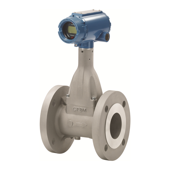
Vortex flow meter
Hide thumbs
Also See for Rosemount 8600 Series:
- Quick start manual (28 pages) ,
- Quick start manual (24 pages)

Related Manuals for Emerson Rosemount 8600 Series


Summary of Contents for Emerson Rosemount 8600 Series
- Page 1 Reference Manual 00809-0100-4860, Rev BF May 2019 Rosemount ™ 8600 Series Vortex Flow Meter...
-
Page 3: Table Of Contents
Reference Manual Table of Contents 00809-0100-4860, Rev BF May 2019 Contents 1.1 How to use this manual..........1 1.2 Safety messages . - Page 4 Reference Manual Table of Contents May 2019 00809-0100-4860, Rev BF 3.4.1 Failure mode vs. saturation output values ......27 3.4.2 LCD indicator option .
- Page 5 Reference Manual Table of Contents 00809-0100-4860, Rev BF May 2019 5Section 5: Troubleshooting 5.1 Safety messages ............65 5.2 Troubleshooting tables .
- Page 6 Reference Manual Table of Contents May 2019 00809-0100-4860, Rev BF C.2.5 Calculating output variables with known input frequency ..108 C.3 Examples ............110 C.3.1 English units .
- Page 7 Read this manual before working with the product. For personal and system safety, and for optimum product performance, make sure you thoroughly understand the contents before installing, using, or maintaining this product. Within the United States, Emerson Process Management has two toll-free assistance numbers: Customer Central Technical support, quoting, and order-related questions.
- Page 8 Reference Manual Title Page May 2019 00809-0100-4860, Rev BF viii Title Page...
-
Page 9: How To Use This Manual
Reference Manual Introduction May 2019 00809-0100-4860, Rev BF Section 1 Introduction How to use this manual This manual provides installation, configuration, troubleshooting, and other procedures for the use of the Rosemount ™ 8600D Vortex Flowmeter. Specifications and other important information are also included. Section 2: Configuration contains information on entering and verifying basic configuration parameters. - Page 10 Reference Manual Introduction May 2019 00809-0100-4860, Rev BF Rosemount 8600 Vortex Flow Meter...
-
Page 11: Review
Reference Manual Configuration May 2019 00809-0100-4860, Rev BF Section 2 Configuration Review ..............page 3 Process variables . -
Page 12: Primary Variable (Pv)
Reference Manual Configuration May 2019 00809-0100-4860, Rev BF 2.2.1 Primary Variable (PV) FastKeys 1, 1, 1 The measured value of the variable mapped to the primary variable. This can be either Process Temperature (MTA option only) or Flow. Flow variables are available as mass, volume, or velocity. - Page 13 Reference Manual Configuration May 2019 00809-0100-4860, Rev BF Volume flow units FastKeys 1, 1, 4, 1, 2 Allows the user to select the volumetric flow units from the available list. Volumetric Unit LCD Display Field Communicator U.S. Gallons per second GAL/S gal/s U.S.
- Page 14 Reference Manual Configuration May 2019 00809-0100-4860, Rev BF Standard/Normal flow units StdCuft/min SCFH NCMM NmlCum/h NCMD Note When configuring Standard or Normal Flow units to the volumetric flow, a density ratio must be provided. See the Density/Density Ratio on page 13. Special units FastKeys 1, 1, 4, 1, 3...
- Page 15 Reference Manual Configuration May 2019 00809-0100-4860, Rev BF Base time unit FastKeys 1, 1, 4, 1, 3, 2 Provides the time unit from which to calculate the special units. For example, if your special units is a volume per minute, select minutes. Choose from the following units: Seconds (s) ...
- Page 16 Reference Manual Configuration May 2019 00809-0100-4860, Rev BF Mass Flow Units lb/s STon/min lb/min STon/h lb/h STon/d lb/d MetTon/mi kg/s MetTon/h kg/min MetTon/d kg/h kg/d g/min Note If you select a Mass Units option, you must enter process density in your configuration. See the Density/Density Ratio section on page 13.
- Page 17 Reference Manual Configuration May 2019 00809-0100-4860, Rev BF Total FastKeys 1, 1, 4, 4, 1 Provides the output reading of the totalizer. Its value is the amount of liquid or gas that has passed through the flowmeter since the totalizer was last reset. Start FastKeys 1, 1, 4, 4, 2...
- Page 18 Reference Manual Configuration May 2019 00809-0100-4860, Rev BF Electronics temperature FastKeys 1, 1, 4, 7 Allows users to view the electronics temperature value and units. Also allows the user to configure the units for the electronics temperature. Electronics temperature FastKeys 1, 1, 4, 7, 1 Displays the current electronics temperature value and units.
- Page 19 Reference Manual Configuration May 2019 00809-0100-4860, Rev BF Process temperature FastKeys 1, 1, 4, 9 Allows users to view the process temperature value when the vortex transmitter has the temperature sensor option. Also allows the user to configure the process temperature units.
-
Page 20: Basic Setup
Reference Manual Configuration May 2019 00809-0100-4860, Rev BF CJ temperature units FastKeys 1, 1, 4, -, 2 Allows the user to configure the units for the thermocouple cold junction temperature from the available list. deg C deg F deg R ... - Page 21 Reference Manual Configuration May 2019 00809-0100-4860, Rev BF Process fluid FastKeys 1, 3, 2, 2 Select the fluid type: either Liquid, Gas/Steam, Tcomp Sat Steam. Tcomp Sat Steam requires the MTA Option and provides a temperature compensated mass flow output for saturated steam.
- Page 22 Reference Manual Configuration May 2019 00809-0100-4860, Rev BF Density ratio FastKeys 1, 3, 2, 4, 1, 1 Used to convert actual volumetric flow to standard volumetric flow rates based on the following equations: density at actual (flowing) conditions DensityRatio -------------------------------------------------------------------------------------------------------- density at s dard (base) conditions...
-
Page 23: Reference K-Factor
The reference K-factor is a factory calibration number relating the flow through the meter to the shedding frequency measured by the electronics. Every Rosemount 8600 meter manufactured by Emerson is run through a water calibration to determine this value. 2.3.4... -
Page 24: Mating Pipe Id (Inside Diameter)
Reference Manual Configuration May 2019 00809-0100-4860, Rev BF 2.3.5 Mating pipe ID (Inside Diameter) FastKeys 1, 3, 5 The Pipe ID (Inside Diameter) of the pipe adjacent to the flowmeter can cause entrance effects that may alter flowmeter readings. You must specify the exact inside diameter of the pipe to correct for these effects. -
Page 25: Pv Units
Reference Manual Configuration May 2019 00809-0100-4860, Rev BF 2.3.7 PV units FastKeys 1, 3, 7 Selections for this include all units available for the selection of PV. This will set the units for the flow rate or process temperature. 2.3.8 Range values FastKeys 1, 3, 8... -
Page 26: Auto Adjust Filter
Reference Manual Configuration May 2019 00809-0100-4860, Rev BF 2.3.10 Auto adjust filter FastKeys 1,3, Scroll to Bottom The Auto Adjust Filter is a function that can be used to optimize the range of the flowmeter based on the density of the fluid. The electronics uses process density to calculate the minimum measurable flow rate, while retaining at least a 4:1 signal to the trigger level ratio. - Page 27 Reference Manual Configuration May 2019 00809-0100-4860, Rev BF Figure 2-1. Field Communicator Menu Tree for the Rosemount 8600D 1. Process 1. PV 1. Volumetric Flow 1. Volume Flow 1. Base Volume Unit 2. PV % Range 2. Mass Flow 2. Units 2.
- Page 28 Reference Manual Configuration May 2019 00809-0100-4860, Rev BF Table 2-2. Field Communicator Fast Key Sequences for the Rosemount 8600D Function Fast Keys Function Fast Keys Alarm Jumper 1, 4, 2, 1, 3 Message 1, 4, 4, 4 Analog Output (Config) 1, 4, 2, 1 Meter Body Number 1, 4, 1, 5...
-
Page 29: Safety Messages
Reference Manual Installation May 2019 00809-0100-4860, Rev BF Section 3 Installation Safety messages ............page 21 Commissioning . - Page 30 Reference Manual Installation May 2019 00809-0100-4860, Rev BF Figure 3-1. Installation Flowchart Bench START HERE Commissioning? FIELD INSTALL Review CONFIGURE Configuration Mount Configuration Flowmeter Process Config • Transmitter Mode • Process Fluid • Fixed Process Temp. Mount • Dens/Dens Ratio Conduit Go to -Density Ratio...
-
Page 31: Commissioning
Reference Manual Installation May 2019 00809-0100-4860, Rev BF Commissioning Commission the Rosemount 8600D before putting it into operation. This ensures proper configuration and operation of the meter. It also enables you to check hardware settings, test the flowmeter electronics, verify flowmeter configuration data, and check output variables. - Page 32 Reference Manual Installation May 2019 00809-0100-4860, Rev BF Horizontal installation For horizontal installation, the preferred orientation is to have the electronics installed to the side of the pipe. In liquid applications, this ensures any entrapped air or solids do not strike the shedding bar and disrupt the shedding frequency.
- Page 33 Reference Manual Installation May 2019 00809-0100-4860, Rev BF Upstream/Downstream piping The vortex meter may be installed with a minimum of ten diameters (D) of straight pipe length upstream and five diameters (D) of straight pipe length downstream. Rated accuracy is based on the number of pipe diameter from an upstream disturbance. No K-factor correction is required if the meter is installed with 35 D upstream and 5 D downstream.
-
Page 34: Wetted Material Selection
Reference Manual Installation May 2019 00809-0100-4860, Rev BF 3.2.4 Wetted material selection Ensure the process fluid is compatible with the meter body wetted materials when specifying the Rosemount 8600D. Corrosion will shorten the life of the meter body. Consult recognized sources of corrosion data or contact your Rosemount Sales Representative for more information. -
Page 35: Failure Mode Vs. Saturation Output Values
Reference Manual Installation May 2019 00809-0100-4860, Rev BF Set these jumpers during the commissioning stage to avoid exposing the electronics to the plant environment. Figure 3-5. Alarm and Security Jumpers Alarm As part of normal operations, the Rosemount 8600D continuously runs a self-diagnostic routine. -
Page 36: Lcd Indicator Option
Reference Manual Installation May 2019 00809-0100-4860, Rev BF Table 3-1. Analog Output: Standard Alarm Values vs. Saturation Values Level 4—20 mA Saturation Value 4—20 mA Alarm Value 3.9 mA < 3.75 mA 21.75 mA High 20.8 mA Table 3-2. Analog Output: NAMUR-Compliant Alarm Values vs. Saturation Values Level 4—20 mA Saturation Value 4—20 mA Alarm Value... -
Page 37: Flow Direction
Reference Manual Installation May 2019 00809-0100-4860, Rev BF Note Do not lift the flowmeter by the transmitter. Lift the meter by the meter body. If necessary, Lifting supports can be tied around the meter body as shown in Figure 3-7. Figure 3-7. -
Page 38: Flange Bolts
Reference Manual Installation May 2019 00809-0100-4860, Rev BF 3.5.4 Flange bolts Install the Rosemount 8600D Flowmeter between two conventional pipe flanges, as shown Figure 3-8 on page Figure 3-8. Flanged-Style Flowmeter Installation Flow A. Installation bolts and nuts (supplied by customer) B. -
Page 39: Flowmeter Grounding
Reference Manual Installation May 2019 00809-0100-4860, Rev BF Figure 3-9. Flange Bolt Torquing Sequence 3.5.6 Flowmeter grounding Grounding is not required in typical vortex applications; however, a proper ground will eliminate possible noise pickup by the electronics. Grounding straps may be used to ensure that the meter is grounded to the process piping. -
Page 40: Conduit Connections
Reference Manual Installation May 2019 00809-0100-4860, Rev BF 3.6.2 Conduit connections The electronics housing has two ports for –14 NPT or M2031.5 conduit connections. Unless marked otherwise conduit entries in the housing are NPT. These connections are made in a conventional manner in accordance with local or plant electrical codes. Be sure to properly seal unused ports to prevent moisture or other contamination from entering the terminal block compartment of the electronics housing. -
Page 41: Grounding The Transmitter Case
Reference Manual Installation May 2019 00809-0100-4860, Rev BF 3.6.5 Grounding the transmitter case The transmitter case should always be grounded in accordance with national and local electrical codes. The most effective transmitter case grounding method is direct connection to earth ground with minimal impedance. Methods for grounding the transmitter case include: Internal Ground Connection: The Internal Ground Connection screw is inside the ... - Page 42 Reference Manual Installation May 2019 00809-0100-4860, Rev BF Typical single loop wiring diagram: 8600 terminals loop Loop Load Calculation = (V – 10.8) / 0.024 loop(max) Where: = 250 Ω. Required for HART communication. loop(min) = The maximum value the loop load resistor can be. ...
- Page 43 10.15 16.14 25.67 Note If an Emerson Smart Wireless THUM ™ Adapter is being used with the Rosemount 8600 flowmeter to exchange information via the WirelessHART protocol, an additional 2.5 Vdc is dropped in the connected loop. This is because the THUM is wired in series with the transmitter.
- Page 44 Reference Manual Installation May 2019 00809-0100-4860, Rev BF The flowmeter provides an isolated transistor switch-closure frequency output signal proportional to flow, as shown in Figure 3-12. The frequency limits are as follows: Maximum Frequency = 10000 Hz Minimum Frequency = 0.0000035 Hz (1 pulse/79 hours) ...
- Page 45 Reference Manual Installation May 2019 00809-0100-4860, Rev BF If the flowmeter is protected by the optional transient protector, you must provide a high-current ground connection from the electronics housing to earth ground. Also, tighten the ground screw in the bottom center of the terminal block to provide a good ground connection.
-
Page 46: Remote Electronics
Reference Manual Installation May 2019 00809-0100-4860, Rev BF Figure 3-15. 4–20 mA and Pulse Wiring with Electronic Totalizer/ Counter 250 – A. Test ammeter B. Pulse counter 3.6.7 Remote electronics If you order one of the remote electronics options (options R10, R20, R30, R33, R50, or RXX), the flowmeter assembly will be shipped in two parts: The meter body with an adapter installed in the bracket and an interconnecting coaxial cable attached to it. - Page 47 Reference Manual Installation May 2019 00809-0100-4860, Rev BF Figure 3-16. Remote Electronics Installation Note Consult factory for SST installation. A. Meter body in. NPT Conduit adapter or cable gland (supplied by customer) B. Bracket J. Electronics housing C. Sensor cable nut K.
-
Page 48: Calibration
Reference Manual Installation May 2019 00809-0100-4860, Rev BF Attach the coaxial cable ground wire to the housing via the housing base ground screw. Attach and securely tighten the coaxial cable nut to the connection on the electronics housing. Align the housing adapter with the housing and attach with two screws. Tighten the conduit adapter or cable gland to the housing adapter. - Page 49 Reference Manual Installation May 2019 00809-0100-4860, Rev BF Figure 3-17. Rosemount 8600D with Optional Indicator A. Electronics board The indicator features an eight-character (and five alphanumeric) liquid crystal display that gives a direct reading of the digital signal from the microprocessor. During normal operation, the display can be configured to alternate between the following readings: Primary variable in engineering units ...
-
Page 50: Installing The Indicator
Reference Manual Installation May 2019 00809-0100-4860, Rev BF Figure 3-18 shows the indicator display with all segments lit. Figure 3-18. Optional Liquid Crystal Display A HART-based communicator can be used to change the engineering units of the parameters displayed on the indicator. (SeeSection 4: Operation for more information). -
Page 51: Transient Protection
Reference Manual Installation May 2019 00809-0100-4860, Rev BF Insert the connector into the Alarm / Security junction. Gently slide the LCD indicator onto the connector and tighten the screws into place. Insert jumpers into ALARM and SECURITY positions on the face of the LCD indicator. - Page 52 Reference Manual Installation May 2019 00809-0100-4860, Rev BF If the flowmeter is installed in a loop, secure the loop and disconnect power. Remove the field terminal side flowmeter cover. Remove the captive screws. Remove the housing ground screw. Use pliers to pull the terminal block out of the housing. Inspect the connector pins for straightness.
-
Page 53: Diagnostics/Service
Reference Manual Operation May 2019 00809-0100-4860, Rev BF Section 4 Operation Diagnostics/service ........... . . page 45 Advanced functionality . -
Page 54: Loop Test
Reference Manual Operation May 2019 00809-0100-4860, Rev BF Min/Max electronics temperatures FastKeys 1, 2, 1, 4 Allows the user to view the minimum and maximum temperatures that the electronics have been exposed to. Min electronics temp FastKeys 1, 2, 1, 4, 1 Displays the lowest temperature that the electronics have been exposed to. -
Page 55: Flow Simulation
Reference Manual Operation May 2019 00809-0100-4860, Rev BF 4.1.4 Flow simulation FastKeys 1, 2, 4 Enables you to check the electronics functionality. This can be verified with either the Flow Simulation Internal or Flow Simulation External method. PV must be Volume Flow, Velocity Flow, or Mass Flow before Flow Simulation can be used. -
Page 56: D/A Trim(Digital-To-Analog Trim)
Reference Manual Operation May 2019 00809-0100-4860, Rev BF Enable normal flow FastKeys 1, 2, 4, 4 Allows you to exit the flow simulation mode (internal or external) and return to normal operation mode. Enabled Normal Flow must be activated after any simulation is run. Failure to enable normal flow will leave the Vortex in simulation mode. -
Page 57: Shed Freq At Urv
Reference Manual Operation May 2019 00809-0100-4860, Rev BF 4.1.7 Shed freq at URV FastKeys 1, 2, 7 Gives the shedding frequency corresponding to your URV (URV = Upper Range Value). If the PV is Process Temperature, the Shedding Frequency at URV represents the shedding frequency of the Volumetric Flow URV. - Page 58 Reference Manual Operation May 2019 00809-0100-4860, Rev BF Mating pipe I.D. FastKeys 1, 4, 1, 2 The inside diameter of the pipe adjacent to the flow meter can cause entrance effects that may alter flowmeter readings. The exact inside diameter of the pipe must be specified to correct for these effects.
-
Page 59: Configure Outputs
Reference Manual Operation May 2019 00809-0100-4860, Rev BF 4.3.2 Configure outputs FastKeys 1, 4, 2 The Rosemount 8600D is digitally adjusted at the factory using precision equipment to ensure accuracy. You should be able to install and operate the flowmeter without a D/A Trim. - Page 60 Reference Manual Operation May 2019 00809-0100-4860, Rev BF Alarm level select FastKeys 1, 4, 2, 1, 5 Allows you to select the alarm level of the transmitter. Either Rosemount standard or NAMUR compliant. Alarm/sat levels FastKeys 1, 4, 2, 1, 6 Displays alarm and saturation mA output levels.
- Page 61 Reference Manual Operation May 2019 00809-0100-4860, Rev BF Pulse output FastKeys 1, 4, 2, 2, 1 The Rosemount 8600D comes with an optional pulse output option (P). This enables the flowmeter to output the pulse rate to an external control system, totalizer, or other device. If the flowmeter was ordered with the pulse mode option, it may be configured for either pulse scaling (based on rate or unit) or shedding frequency output.
- Page 62 Reference Manual Operation May 2019 00809-0100-4860, Rev BF Scaled velocity FastKeys 1, 4, 2, 2, 1, 4 Allows you to configure the pulse output based on a velocity Flow Rate. Pulse scaling rate FastKeys 1, 4, 2, 2, 1, 4, 1 Allows the user to set a certain velocity flow rate to a desired frequency.
- Page 63 Reference Manual Operation May 2019 00809-0100-4860, Rev BF Pulse output test FastKeys 1, 4, 2, 2, 2 A fixed frequency mode test that checks the integrity of the pulse loop. It tests that all connections are good and that pulse output is running on the loop. HART output FastKeys 1, 4, 2, 3...
- Page 64 Reference Manual Operation May 2019 00809-0100-4860, Rev BF Poll address FastKeys 1, 4, 2, 3, 1 Enables you to set the poll address for a multi-dropped meter. The poll address is used to identify each meter on the multi-drop line. Follow the on-screen instructions to set the address at a number from 1 to 15.
- Page 65 Reference Manual Operation May 2019 00809-0100-4860, Rev BF The Burst Mode variable enables you to set the Burst Mode to the needs of your application. Options for the Burst Mode setting include: Off–Turns off the Burst Mode so that no data are broadcast on the loop. On–Turns Burst Mode on so that the data selected under Burst Option are broadcast over the loop.
- Page 66 Reference Manual Operation May 2019 00809-0100-4860, Rev BF XMTR variable slot 2 FastKeys 1, 4, 2, 3, 6, 2 User selected Burst Variable 2. XMTR variable slot 3 FastKeys 1, 4, 2, 3, 6, 3 User selected Burst Variable 3. XMTR variable slot 4 FastKeys 1, 4, 2, 3, 6, 4...
-
Page 67: Signal Processing
Reference Manual Operation May 2019 00809-0100-4860, Rev BF 4.3.3 Signal processing FastKeys 1, 4, 3 The Rosemount 8600D and its HART-based communications feature enable you to filter out noise and other frequencies from the transmitter signal. The four user-alterable parameters associated with the digital signal processing on the Rosemount 8600D include low-pass filter corner frequency, low-flow cutoff, trigger level, and damping. - Page 68 Reference Manual Operation May 2019 00809-0100-4860, Rev BF Signal/trigger level ratio ( Sig/Tr) FastKeys 1, 4, 3, 1, 3 A variable that indicates the flow signal strength to trigger level ratio. This ratio indicates if there is enough flow signal strength for the meter to work properly. For accurate flow measurement, the ratio should be greater than 4:1.
- Page 69 Reference Manual Operation May 2019 00809-0100-4860, Rev BF Low flow cutoff FastKeys 1, 4, 3, 2, 3 Enables you to adjust the filter for noise at no flow. It is set at the factory to handle most applications, but certain applications may require adjustment either to expand measurability or to reduce noise.
-
Page 70: Device Information
Reference Manual Operation May 2019 00809-0100-4860, Rev BF Damping FastKeys 1, 4, 3, 4 Changes the response time of the flowmeter to smooth variations in output readings caused by rapid changes in input. The appropriate damping setting can be determined based on the necessary response time, signal stability, and other requirements of the loop dynamics in your system. - Page 71 Reference Manual Operation May 2019 00809-0100-4860, Rev BF FastKeys 1, 4, 4, 2 The quickest variable to identify and distinguish between flowmeters. Flowmeters can be tagged according to the requirements of your application. The tag may be up to eight characters long.
- Page 72 Reference Manual Operation May 2019 00809-0100-4860, Rev BF Universal rev FastKeys 1, 4, 4, 8, 1 Designates the HART Universal Command specification to which the transmitter is designed to conform. Transmitter rev FastKeys 1, 4, 4, 8, 2 Designates the revision for Rosemount 8600D specific command identification for HART compatibility.
-
Page 73: Safety Messages
Reference Manual Troubleshooting May 2019 00809-0100-4860, Rev BF Section 5 Troubleshooting Safety messages ............page 65 Troubleshooting tables . -
Page 74: Troubleshooting Tables
Reference Manual Troubleshooting May 2019 00809-0100-4860, Rev BF Explosions could result in death or serious injury. Do not remove the transmitter cover or thermocouple (MTA option only) from the electronics housing in explosive atmospheres when the circuit is alive. Before connecting a HART-based communicator in an explosive atmosphere, ... -
Page 75: Advanced Troubleshooting
Reference Manual Troubleshooting May 2019 00809-0100-4860, Rev BF Symptom Corrective action Flow in Pipe, No Output Basics Application Problems • Check to make the sure that the meter is • Calculate expected frequency (see installed with the arrow in the direction of Appendix Appendix C Electronics process flow. - Page 76 Reference Manual Troubleshooting May 2019 00809-0100-4860, Rev BF Message Description DIGITAL FILTER ERROR The digital filter in the transmitter electronics is not reporting. The transmitter will remain in ALARM until the digital signal processor resumes reporting flow data. COPROCESSOR ERROR If this occurs at power-up, the RAM/ROM test in the coprocessor has failed.
-
Page 77: Electronics Test Points
Reference Manual Troubleshooting May 2019 00809-0100-4860, Rev BF Message Description INTERNAL SIGNAL FAULT The flow data encoded on a pulse signal from the Sigma-Delta ASIC to VDSP has been lost. A power cycle may resolve the problem. Also check the inter-board connector. -
Page 78: Tp1
Reference Manual Troubleshooting May 2019 00809-0100-4860, Rev BF The simulated signal amplitude is based on the transmitter required minimum process density. The signal being simulated can be one of several profiles—a simulated signal of constant frequency or a simulated signal representative of a ramping flow rate. The electronics verification procedure is described in detail in Appendix C: Electronics Verification. -
Page 79: Diagnostic Messages On Lcd
Reference Manual Troubleshooting May 2019 00809-0100-4860, Rev BF Figure 5-4. Noisy Signals 3.0 V A. Vortex signal (TP1) B. Trigger level C. Shedding frequency output Figure 5-5. Improper Sizing/Filtering 3.0 V A. Trigger level B. Vortex signal (TP1) C. Shedding frequency output Diagnostic messages on LCD In addition to the output, the LCD indicator displays diagnostic messages for troubleshoot- ing the flowmeter. - Page 80 Reference Manual Troubleshooting May 2019 00809-0100-4860, Rev BF FAULT_EEROM The flowmeter electronics has undergone a EEPROM checksum fault. Contact your Field Service Center. FAULT_RAM The flowmeter electronics has undergone a RAM test fault. Contact your Field Service Center. FAULT_ASIC The flowmeter electronics has undergone a digital signal processing ASIC update fault. Contact your Field Service Center.
-
Page 81: Testing Procedures
Reference Manual Troubleshooting May 2019 00809-0100-4860, Rev BF FAULT_TC (MTA option only) The temperature sensor that is used to measure the process temperature has failed. Contact your Field Service Center. FAULT_RTD (MTA option only) The RTD for cold junction compensation has failed. Contact your Field Service Center. SIGNAL_SIMUL The transmitter flow signal is being simulated by a signal generator internal to the transmitter. -
Page 82: Replacing The Terminal Block In The Housing
Reference Manual Troubleshooting May 2019 00809-0100-4860, Rev BF 5.6.1 Replacing the terminal block in the housing To replace the Field Terminal Block in the housing, you will need a small screwdriver. Use the following procedure to replace the terminal block in the housing of the Rosemount 8600D. -
Page 83: Replacing The Electronics Boards
Reference Manual Troubleshooting May 2019 00809-0100-4860, Rev BF Install the terminal block Align the socketed holes on the back side of the terminal block over the pins protruding from the bottom of the housing cavity in the terminal block side of the electronics housing. - Page 84 Reference Manual Troubleshooting May 2019 00809-0100-4860, Rev BF Figure 5-7. Electronics Boards Assembly A. Electronics boards If the meter has the LCD indicator option, loosen the two screws. Remove the LCD and the connector from the electronics board. Loosen the three captive screws that anchor the electronics. Use pliers or a flathead screwdriver to carefully remove the sensor cable clip from the electronics.
-
Page 85: Replacing The Electronics Housing
Reference Manual Troubleshooting May 2019 00809-0100-4860, Rev BF Install the electronics boards Verify that power to the Rosemount 8600D is off. Align the sockets on the bottom of the two electronics boards over the pins protruding from the bottom of the housing cavity. Carefully guide the sensor cable through the notches on the edge of the circuit boards. -
Page 86: Replacing The Sensor
Reference Manual Troubleshooting May 2019 00809-0100-4860, Rev BF Use a -in. (4 mm) hex wrench to loosen the housing rotation screws (at the base of the electronics housing) by turning screws clockwise (inward) until they clear the bracket. Slowly pull the electronics housing no more than 1.5-in. (40 mm) from the top of the bracket. - Page 87 Reference Manual Troubleshooting May 2019 00809-0100-4860, Rev BF Tools needed -in. (4 mm) hex wrench -in. (8 mm) open end wrench 5 mm hex wrench Suction or compressed air device Small, soft bristle brush Cotton swabs ...
- Page 88 Reference Manual Troubleshooting May 2019 00809-0100-4860, Rev BF Note Do not scratch or deform any part of the sensor. Carefully brush the sealing surface clean with a soft bristle brush. Moisten a cotton swab with an appropriate cleaning liquid. Wipe the sealing surface. Repeat several times if necessary with a clean cotton swab until there is minimal dirt residue picked up by the cotton swab.
-
Page 89: Remote Electronics Procedure
Reference Manual Troubleshooting May 2019 00809-0100-4860, Rev BF 5.6.5 Remote electronics procedure If the Rosemount 8600D electronics housing is mounted remotely, some replacement procedures are different than for the flowmeter with integral electronics. The following procedures are exactly the same: Replacing the Terminal Block in the Housing (see page 74). - Page 90 Reference Manual Troubleshooting May 2019 00809-0100-4860, Rev BF Figure 5-10. Coaxial Cable Connections A. Meter Body B. bracket C. Sensor Cable Nut D. Nut E. Washer F. Union G. Meter Adapter H. Coaxial Cable I. ? NPT Conduit Adapter or Cable Gland (Supplied by Customer) Detach the meter adapter The above instructions will provide access to the meter body.
-
Page 91: Coaxial Cable At The Electronics Housing
Reference Manual Troubleshooting May 2019 00809-0100-4860, Rev BF Loosen and remove the sensor cable nut from the other end of the union. Loosen and disconnect the conduit adapter or cable gland from the meter adapter. Attach the meter adapter If you are using a conduit adapter or cable gland, slide it over the plain end of the coaxial cable (the end without a ground wire). - Page 92 Reference Manual Troubleshooting May 2019 00809-0100-4860, Rev BF Figure 5-11. Remote Electronics Exploded View A. Housing adapter screws B. Housing adapter C. Housing base screw D. Ground connection E. Electronics housing F. Coaxial cable nut G. Conduit adapter (optional-supplied by customer) Loosen the conduit adapter (or cable gland) from the housing adapter.
-
Page 93: Changing The Housing Orientation
Reference Manual Troubleshooting May 2019 00809-0100-4860, Rev BF Align the housing adapter with the housing base and attach with the two housing adapter screws. Tighten the conduit adapter to the housing adapter. 5.6.7 Changing the housing orientation The entire electronics housing may be rotated in 90 degree increments for easy viewing. Use the following steps to change the housing orientation: Loosen the screw on the access cover on the bracket (if present) and remove the cover. -
Page 94: Return Of Material
Reference Manual Troubleshooting May 2019 00809-0100-4860, Rev BF Note Use plant approved procedure for removing a temperature sensor from a thermowell. Remove temperature sensor from electronics by using a 2.5 mm allen wrench to remove cap head screw from electronics. Gently pull temperature sensor from electronics. -
Page 95: A.1 Specifications
Reference Manual Specifications and Reference Data May 2019 00809-0100-4860, Rev BF Appendix A Specifications and Reference Data Specifications ............page 87 Functional specifications . - Page 96 Reference Manual Specifications and Reference Data May 2019 00809-0100-4860, Rev BF Table A-3. Maximum Measurable Meter Power supply Velocities HART analog (Use the smaller of the two values) External power supply required. Flowmeter operates on 10.8 to 42 Vdc terminal voltage (with 250-ohm Feet per Second Meters per Second minimum load required for HART communications, Liquids...
- Page 97 Reference Manual Specifications and Reference Data May 2019 00809-0100-4860, Rev BF Optional LCD indicator Table A-4. Determining the PPL The optional LCD indicator is capable of displaying: English Units SI Units Meter Primary Variable Style Liquid Liquid Velocity Flow 8600DF 3.4 ? 10 1.9 ? 10...
-
Page 98: A.3 Typical Flow Ranges
Reference Manual Specifications and Reference Data May 2019 00809-0100-4860, Rev BF Damping Overrange capability HART analog Flow Damping adjustable between 0.2 and 255 seconds. Analog signal output continues to 105 percent of span, Process Temperature Damping adjustable between 0.4 and then remains constant with increasing flow. - Page 99 Reference Manual Specifications and Reference Data May 2019 00809-0100-4860, Rev BF Table A-5. Typical pipe velocity ranges for 8600D Process Line Liquid Velocity Ranges Gas Velocity Ranges Size (Inches/ DN) Vortex Meter (ft/s) (m/s) (ft/s) (m/s) 1/ 25 8600DF010 0.70 to 25.0 0.21 to 7.6 6.50 to 250.0 1.98 to 76.2...
- Page 100 Reference Manual Specifications and Reference Data May 2019 00809-0100-4860, Rev BF Table A-8. Air Flow Rate Limits at 59 °F (15 °C)–Line Sizes 3- through 4-in. Minimum and Maximum Air Flow Rates for line sizes 3-in./DN 80 through 4-in./DN 100 Process Flow Rate 3-in./DN 80...
- Page 101 Reference Manual Specifications and Reference Data May 2019 00809-0100-4860, Rev BF Notes The Rosemount 8600D measures the volumetric flow under operating conditions (i.e. the actual volume at the operating pressure and temperature–acfm or acmh), as shown above. However, gas volumes are strongly dependent on pressure and temperature.
- Page 102 Reference Manual Specifications and Reference Data May 2019 00809-0100-4860, Rev BF Table A-11. Saturated Steam Flow Rate Limits –Line Sizes 3- through 4-in. Minimum and Maximum Saturated Steam Flow Rates for line sizes 3-in./DN 80 through 4-in./DN 100 Process Flow Rate 3-in./DN 80 4-in./DN 100 Pressure...
-
Page 103: A.4 Performance Specifications
Reference Manual Specifications and Reference Data May 2019 00809-0100-4860, Rev BF A.4 Performance specifications Analog output Same as pulse output plus an additional 0.025% of span The following performance specifications are for all Repeatability Rosemount models except where noted. Digital ±... -
Page 104: A.5 Physical Specifications
Reference Manual Specifications and Reference Data May 2019 00809-0100-4860, Rev BF Mounting position effect Note Meter will meet accuracy specifications when mounted in Certificate of compliance for MR0175/ISO15156 horizontal, vertical, or inclined pipelines. Best practice for requires Q15 as a separate line item. mounting in a horizontal pipe is to orient the shedder bar in the horizontal plane. -
Page 105: A.6 Dimensional Drawings
Reference Manual Specifications and Reference Data May 2019 00809-0100-4860, Rev BF Pipe length requirements The vortex meter may be installed with a minimum of ten diameters (D) of straight pipe length upstream and five diameters (D) of straight pipe length downstream. Rated Accuracy is based on the number of pipe diameter from an upstream disturbance. - Page 106 Reference Manual Specifications and Reference Data May 2019 00809-0100-4860, Rev BF Figure A-1. Flanged-Style Flowmeter (1-through 8-in./25 through 200 mm Line Sizes) 3.20 2.90 (81) (72) 2.56 1.10 (65) (28) Diameter 3.08 (78.2) 1.00 (25.4) Diameter B Diagram illustrated without MTA Option Diagram illustrated with MTA Option 2.00 2.00...
- Page 107 Reference Manual Specifications and Reference Data May 2019 00809-0100-4860, Rev BF Table A-14. Flanged-Style Flowmeter (1-through 2-in./25 through 50 mm Line Sizes) Nominal Face-to-face A Diameter B Weight Size Flange Rating in. (mm) in. (mm) in. (mm) lb (kg) in. (mm) ANSI 150 5.9 (150) 0.95 (24,1)
- Page 108 Reference Manual Specifications and Reference Data May 2019 00809-0100-4860, Rev BF Table A-16. Flanged-Style Flowmeter (8-in./200 mm Line Sizes) (Refer to Figure A-1) Nominal Flange Face-to-face A Diameter B in. Weight Size in. C in. (mm) Rating in. (mm) (mm) (kg) (mm) ANSI 150...
- Page 109 Reference Manual Specifications and Reference Data May 2019 00809-0100-4860, Rev BF Figure A-3. Flanged Style Remote Mount Flowmeters–Line Sizes 1-through 8-in. (25 through 200 mm) -14 NPT (For Remote Cable Conduit) Flanged Flowmeter Note Dimensions are in inches (millimeters). Table A-17. Remote Mount, Flanged Style Sensor Flowmeter Dimensions Nominal Size in.
- Page 110 Reference Manual Specifications and Reference Data May 2019 00809-0100-4860, Rev BF Rosemount 8600 Vortex Flow Meter...
- Page 111 Reference Manual Product Certifications May 2019 00809-0100-4860, Rev BF Appendix B Product Certifications For detailed approval certification information and installation drawings, please see document number 00825-VA00-0011: Rosemount™ 8600 Series Vortex Flowmeter Approval Document. Rosemount 8600 Vortex Flow Meter...
- Page 112 Reference Manual Product Certifications May 2019 00809-0100-4860, Rev BF Rosemount 8600 Vortex Flow Meter...
-
Page 113: Safety Messages
Reference Manual Electronics Verification May 2019 00809-0100-4860, Rev BF Appendix C Electronics Verification Safety messages ............page 105 Electronics verification . -
Page 114: Electronics Verification Using Flow Simulation Mode
Reference Manual Electronics Verification May 2019 00809-0100-4860, Rev BF choose to physically disconnect the sensor from the electronics, refer to Replacing the electronics housing on page C.2.1 Electronics verification using flow simulation mode FastKeys 1, 2, 4, 3, 1 Electronics verification can be done by utilizing the internal flow simulation functionality. This functionality is available as model option code DS1 at the time of order. -
Page 115: Electronics Verification Using An External Frequency Generator
Reference Manual Electronics Verification May 2019 00809-0100-4860, Rev BF C.2.4 Electronics verification using an external frequency generator If an external frequency source is desirable, then test points on the electronics are available (see Figure C-2). Tools needed Field Communicator or AMS ... -
Page 116: Calculating Output Variables With Known Input Frequency
Reference Manual Electronics Verification May 2019 00809-0100-4860, Rev BF Figure C-2. Test Frequency Output and Chassis Ground Points. Ground Test Frequency In Test Point 1 C.2.5 Calculating output variables with known input frequency Use the following equations with a known input frequency for verification of a flow rate or 4–20 mA output within a given calibrated range. - Page 117 Reference Manual Electronics Verification May 2019 00809-0100-4860, Rev BF To verify a 4–20 mA output For a given input frequency F (Hz), and K-factor (compensated), find output current I: F Hz K C x LRV – ...
-
Page 118: Examples
Reference Manual Electronics Verification May 2019 00809-0100-4860, Rev BF Table C-1. Unit Conversions Units (act) Conversion Factor gal/s 1.00000E+00 gal/m 1.66667E-02 gal/h 2.77778E-04 Impgal/s 1.20095E+00 Impgal/m 2.00158E-02 Impgal/h 3.33597E-04 2.64172E-01 4.40287E-03 7.33811E-05 CuMtr/m 4.40287E-00 CuMtr/h 7.33811E-02 CuFt/m 1.24675E-01 CuFt/h 2.07792E-03 bbl/h 1.16667E-02 kg/s... - Page 119 Reference Manual Electronics Verification May 2019 00809-0100-4860, Rev BF Vortex Frequency = 75 Hz K-factor (compensated) = 10.79 (via Field Communicator or AMS) F Hz = 75.00/(10.79 3 0.0166667) = 417.1 gpm Therefore, an input frequency of 75.00 Hz represents a flow rate of 417.1 gpm in this application.
- Page 120 Reference Manual Electronics Verification May 2019 00809-0100-4860, Rev BF For a given input frequency, you may also determine the current output. Use the Example 2 page 111 with an input frequency of 300 Hz: URV= 40000 lb/hr LRV= 0 lb/hr (Hz) = 300.00 ...
- Page 121 Reference Manual Electronics Verification May 2019 00809-0100-4860, Rev BF URV= 5833 SCFM LRV= 0 SCFM (Hz) = 200.00 F Hz – --------------------------------------------------------------- - URV LRV –...
-
Page 122: Units
Reference Manual Electronics Verification May 2019 00809-0100-4860, Rev BF C.3.2 SI units Example 1 (SI units) Fluid = Water = 2000 lpm Line size = 80 mm. = 0 lpm Line pressure = 700 kPas = 4.40287E-03 (from Table C-1 on page110) Operating = 60 °F... - Page 123 Reference Manual Electronics Verification May 2019 00809-0100-4860, Rev BF Example 2 (SI units) Fluid = Saturated Steam = 3600 kg/hr Line size = 80 mm. = 0 kg/hr Line pressure = 700 kPas from Table C-1 on page 110) Operating = 170 °F Density(...
- Page 124 Reference Manual Electronics Verification May 2019 00809-0100-4860, Rev BF Example 3 (SI units) Fluid = Natural gas = 10,000 NCMH Line size = 80 mm = 0 NCMH Line pressure = 1000 KPas /sp. units factor (from Table C-1 on page110) Operating = 10 °F...
-
Page 125: Overview
Reference Manual ® HART Menu Tree May 2019 00809-0100-4860, Rev BF Appendix D HART ® Menu Tree Overview The Rosemount 8600D HART menu tree is shown in Figure D-1. Rosemount 8600 Vortex Flow Meter... - Page 126 ® Reference Manual HART Menu Tree May 2019 00809-0100-4860, Rev BF Table D-1. Rosemount 8600D HART Menu Tree 1. Process 1. PV 1. Volumetric Flow 1. Volume Flow 1. Base Volume Unit 2. PV % Range 2. Mass Flow 2. Units 2.
- Page 127 Reference Manual Index 00809-0100-4860, Rev BF May 2019 Index ....... . .15 Flow Units .
- Page 128 Reference Manual Index May 2019 00809-0100-4860, Rev BF ......85 Troubleshooting ......90 Turn-on Time .
- Page 130 Reference Manual 00809-0100-4860, Rev BF May 2019...
Need help?
Do you have a question about the Rosemount 8600 Series and is the answer not in the manual?
Questions and answers