
Related Manuals for Emerson Rosemount 8750WB


Summary of Contents for Emerson Rosemount 8750WB
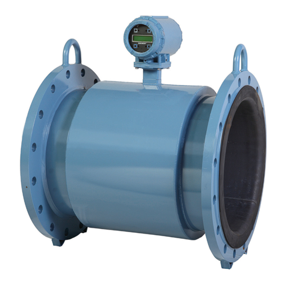
- Page 1 Quick Start Guide 00825-0200-4750, Rev AA February 2014 Rosemount 8750WB Magnetic Flowmeter System for Utility, Water, and Wastewater Applications...
-
Page 2: Table Of Contents
February 2014 Quick Start Guide NOTICE This document provides basic installation guidelines for the Rosemount® 8750W Magnetic Flowmeter System. For comprehensive instructions, for detailed configuration, diagnostics, maintenance, service, installation or troubleshooting, refer to the Rosemount 8750W reference manual (document number 00809-0100-4750 Rev. BA). The manual and this QSG are also available electronically on www.rosemount.com. -
Page 3: Pre-Installation
Quick Start Guide February 2014 Step 1: Pre-installation Before installing the Rosemount 8750W Flowmeter, there are several pre-installation steps that should be completed to make the installation process easier: Identify the options and configurations that apply to your application Set the hardware switches if necessary ... - Page 4 February 2014 Quick Start Guide Figure 2. Wall mount transmitter dimensional drawing WITH STANDARD COVER 9.01 4.31 (229) 0.44 (109) 3.11 2.81 (11) (79) (71) 12.02 (305) 11.15 (283) 2.96 (75) WITH LOI COVER –14 NPT Ground Lug Conduit Connection LOI Keypad (4 Places) Cover...
- Page 5 Quick Start Guide February 2014 Environmental considerations To ensure maximum transmitter life, avoid extreme temperature and excessive vibration. Typical problem areas: high-vibration lines with integrally mounted transmitters warm-climate installations in direct sunlight outdoor installations in cold climates. Remote-mounted transmitters may be installed in the control room to protect the electronics from the harsh environment and provide easy access for configuration or service.
- Page 6 February 2014 Quick Start Guide Hardware jumpers/switches The 8750W electronics board is equipped with user-selectable hardware switches depending on the transmitter model ordered. These switches set the Failure Alarm Mode, Internal/External Analog Power, Internal/External Pulse Power and Transmitter Security. The standard configuration for these switches when shipped from the factory is as follows: Failure Alarm Mode: HIGH...
-
Page 7: Handling
Quick Start Guide February 2014 Step 2: Handling Handle all parts carefully to prevent damage. Whenever possible, transport the system to the installation site in the original shipping containers. Rosemount flow sensors are shipped with end covers that protect it from mechanical damage. For PTFE lined sensors the cover also prevents normal liner relaxation. -
Page 8: Mounting
February 2014 Quick Start Guide Step 3: Mounting Upstream/downstream piping To ensure specification accuracy over widely varying process conditions, install the sensor a minimum of five straight pipe diameters upstream and two pipe Figure 4 diameters downstream from the electrode plane (see Figure 4. - Page 9 Quick Start Guide February 2014 The sensor should be installed in a location that ensures it remains full during operation. Vertical installation with upward process fluid flow keeps the cross-sectional area full, regardless of flow rate. Horizontal installation should be restricted to low piping sections that are normally full.
-
Page 10: Installation
February 2014 Quick Start Guide Step 4: Installation Flanged sensors Gaskets The sensor requires a gasket at each of its connections to adjacent devices or piping. The gasket material selected must be compatible with the process fluid and operating conditions. Gaskets are required on each side of a grounding ring. All other applications (including sensors with lining protectors or a grounding electrode) require only one gasket on each end connection. - Page 11 Quick Start Guide February 2014 Flange bolts Do not bolt one side at a time. Tighten each side simultaneously. Example: 1. Snug upstream 2. Snug downstream 3. Tighten upstream 4. Tighten downstream Do not snug and tighten the upstream side and then snug and tighten the downstream side.
- Page 12 February 2014 Quick Start Guide Table 1. Suggested flange bolt torque values for ASME PTFE liner Neoprene liner Class 150 Class 300 Class 150 Class 300 Size code Line size (pound-feet) (pound-feet) (pound-feet) (pound-feet) 0.5 inch (15 mm) 1 inch (25 mm) 1.5 inch (40 mm) 2 inch (50 mm) 2.5 inch (65 mm)
- Page 13 Quick Start Guide February 2014 Table 2. Suggested flange bolt torque values for EN1092-1 PTFE liner PN10 PN 16 PN 25 PN 40 Size code Line size (Newton-meter) (Newton-meter) (Newton-meter) (Newton-meter) 0.5-inch (15 mm) 1 inch (25 mm) 1.5 inch (40 mm) 2 inch (50 mm)
- Page 14 February 2014 Quick Start Guide Table 2. (cont) Suggested flange bolt torque values for EN1092-1 Neoprene liner PN 10 PN 16 PN 25 PN 40 Size code Line size (Newton-meter) (Newton-meter) (Newton-meter) (Newton-meter) 1 inch (25 mm) 1.5 inch (40 mm) 2 inch (50 mm) 2.5 inch...
-
Page 15: Grounding
Quick Start Guide February 2014 Step 5: Grounding Table 4 to determine which process grounding option to follow for proper installation. The sensor case should be grounded in accordance with national and local electrical codes. Failure to do so may impair the protection provided by the equipment. - Page 16 February 2014 Quick Start Guide Figure 12. Grounding with grounding rings or lining protectors in non-conductive pipe Grounding Rings or Lining Protectors Figure 13. Grounding with reference electrode in conductive unlined pipe...
-
Page 17: Wiring
Quick Start Guide February 2014 Step 6: Wiring This wiring section covers the connection between the transmitter and sensor, the 4-20 mA loop, and supplying power to the transmitter. Follow the conduit information, cable requirements, and disconnect requirements in the sections below. - Page 18 February 2014 Quick Start Guide Run the appropriate size cable through the conduit connections in your magnetic flowmeter system. Run the power cable from the power source to the transmitter. Run the coil drive and electrode cables between the flowmeter sensor and transmitter.
- Page 19 Quick Start Guide February 2014 To order cable specify length as quantity desired. 25 feet = Qty (25) 08732-0753-1003 Table 5. Cable requirements Description Length Part number Coil Drive Cable (14 AWG) 08712-0060-0001 Belden 8720, Alpha 2442 08712-0060-2013 or equivalent Electrode Cable (20 AWG) 08712-0061-0001 Belden 8762, Alpha 2411...
- Page 20 February 2014 Quick Start Guide Table 7. Combination coil and electrode cable Transmitter terminal Sensor terminal Wire gauge Wire color Green Shield Shield Black White Figure 16. Remote mount wiring diagrams...
- Page 21 Integral mount transmitters The interconnecting wire harness for an integral mount transmitter is installed at Figure 18 the factory. See . Do not use cable other than that supplied by Emerson Process Management, Rosemount, Inc. Figure 18. 8750W integral mount wiring Diagram...
- Page 22 February 2014 Quick Start Guide Connecting the 4–20 mA analog signal Cabling considerations If possible, use individually shielded twisted pair cable, either in single pair or multi-pair varieties. Unshielded cables may be used for short distances, provided ambient noise and cross-talk will not adversely impact communication. The minimum conductor size is 0.51mm diameter (#24 AWG) for cable runs less than 1,500 meters (@ 5,000 ft.) and 0.81mm diameter (#20 AWG) for longer distances.
- Page 23 Quick Start Guide February 2014 Figure 20. Wall mount analog signal wiring diagram +4–20 mA –4–20 mA Analog output - connect negative (-)DC to Terminal 8 and positive (+)DC to Figure 20 Terminal 7. See Internal power source The 4–20 mA analog signal loop is powered from the transmitter itself. External power source The 4–20 mA analog signal loop is powered from an external power source.
- Page 24 February 2014 Quick Start Guide Powering the transmitter The 8750W transmitter is designed to be powered by 90-250 VAC, 50–60 Hz, or 12–42 VDC. Before connecting power to the Rosemount 8750W, consider the following standards and be sure to have the proper power supply, conduit, and other accessories.
- Page 25 Quick Start Guide February 2014 Figure 22. AC power supply requirements 0.320 0.300 0.280 0.260 0.240 0.220 0.200 0.180 0.160 0.140 0.120 0.100 Power Supply Voltage (AC RMS) Figure 23. Apparent power Power Supply Voltage (AC RMS) Supply wire requirements Use 10 - 18 AWG wire rated for the proper temperature of the application.
- Page 26 February 2014 Quick Start Guide Table 8. Overcurrent limits Power system Fuse rating Manufacturer 95-250 VAC 2 Amp, Quick Acting Bussman AGC2 or Equivalent 12-42 VDC 3 Amp, Quick Acting Bussman AGC3 or Equivalent Field mount power supply For AC power applications (90-250 VAC, 50-60 Hz), connect AC Neutral to terminal 9 (AC N/L2) and connect AC Line to terminal 10 (AC/L1).
- Page 27 Quick Start Guide February 2014 Figure 25. Wall mount transmitter power connections Fuse AC Line or DC+ AC Neutral or DC– AC Ground or DC Ground Transmitter Power Cable Field mount cover jam screw For transmitter housings shipped with a cover jam screw, the screw should be properly installed once the transmitter has been wired and powered up.
-
Page 28: Basic Configuration
February 2014 Quick Start Guide Step 7: Basic configuration Once the magnetic flowmeter is installed and power has been supplied, the transmitter must be configured through the basic setup. These parameters can be configured through either a local operator interface or a HART communication page 29 device. - Page 29 Quick Start Guide February 2014 Table 9. HART field communicator fast keys for Field mount Function HART Fast Keys Process Variables 1, 1 Primary Variable (PV) 1, 1, 1 PV Percent of Range 1, 1, 2 PV Analog Output (AO) 1, 1, 3 Totalizer Set-Up 1, 1, 4...
- Page 30 February 2014 Quick Start Guide Function HART Fast Keys Simulated Velocity 1,2,3,1,2,4 Actual Velocity 1,2,3,1,2,5 Velocity Deviation 1,2,3,1,2,6 Transmitter Calibration Test Result 1,2,3,1,2,7 Sensor Calibration Deviation 1,2,3,1,2,8 Sensor Calibration Test Result 1,2,3,1,2,9 Coil Circuit Test Result 1,2,3,1,2,10 Electrode Circuit Test Result 1,2,3,1,2,11 Sensor Signature 1,2,3,1,3...
- Page 31 Quick Start Guide February 2014 Function HART Fast Keys Signal Power 1,2,4,6 8714i results 1,2,4,7 Test Condition 1,2,4,7,1 Test Criteria 1,2,4,7,2 8714i Test Result 1,2,4,7,3 Simulated Velocity 1,2,4,7,4 Actual Velocity 1,2,4,7,5 Velocity Deviation 1,2,4,7,6 Transmitter Calibration Test Result 1,2,4,7,7 Tube Calibration Deviation 1,2,4,7,8 Tube Calibration Test Result 1,2,4,7,9...
- Page 32 February 2014 Quick Start Guide Function HART Fast Keys PV Upper Range Value (URV) 1,3,4 PV Lower Range Value (LRV) 1,3,5 Calibration Number 1,3,6 PV Damping 1,3,7 Detailed Setup Additional Parameters 1,4,1 Coil Drive Frequency 1,4,1,1 Density Value 1,4,1,2 PV Upper Sensor Limit (USL) 1,4,1,3 PV Lower Sensor Limit (LSL) 1,4,1,4...
- Page 33 Quick Start Guide February 2014 Function HART Fast Keys Gross Total 1,4,2,5,2 Net Total 1,4,2,5,3 Reverse Total 1,4,2,5,4 Start Totalizer 1,4,2,5,5 Stop Totalizer 1,4,2,5,6 Reset Totalizer 1,4,2,5,7 Alarm Level 1,4,2,6 HART Output 1,4,2,7 Variable Mapping 1,4,2,7,1 TV is 1,4,2,7,1,1 4V is 1,4,2,7,1,2 Poll Address 1,4,2,7,2...
- Page 34 February 2014 Quick Start Guide Function HART Fast Keys Universal Trim 1,4,5 Device Info 1,4,6 Manufacturer 1,4,6,1 1,4,6,2 Descriptor 1,4,6,3 Message 1,4,6,4 Date 1,4,6,5 Device ID 1,4,6,6 PV Sensor Serial Number 1,4,6,7 Sensor Tag 1,4,6,8 Write Protect 1,4,6,9 Revision No. 1,4,6,10 Universal Rev 1,4,6,10,1...
- Page 35 Quick Start Guide February 2014 Table 10. HART field communicator fast keys for wall mount Function HART Fast Keys Process Variables (PV) Primary Variable Value 1,1,1 Primary Variable% 1,1,2 PV Loop Current 1,1,3 Totalizer Set-Up 1,1,4 Totalizer Units 1,1,4,1 Gross Total 1,1,4,2 Net Total 1,1,4,3...
- Page 36 February 2014 Quick Start Guide Function HART Fast Keys Flow Limit Hysteresis 1,2,2,6,5 Flow Limit 2 1,2,2,7 Control 2 1,2,2,7,1 Mode 2 1,2,2,7,2 High Limit 2 1,2,2,7,3 Low Limit 2 1,2,2,7,4 Flow Limit Hysteresis 1,2,2,7,5 Total Limit 1,2,2,8 Total Control 1,2,2,8,1 Total Mode 1,2,2,8,2...
- Page 37 Quick Start Guide February 2014 Function HART Fast Keys Coil Resistance 1,2,3,1,3,1,1 Coil Signature 1,2,3,1,3,1,2 Electrode Resistance 1,2,3,1,3,1,3 Re-Signature Meter 1,2,3,1,3,2 Recall Last Saved Values 1,2,3,1,3,3 Set Pass/Fail Criteria 1,2,3,1,4 No Flow Limit 1,2,3,1,4,1 Flowing Limit 1,2,3,1,4,2 Empty Pipe Limit 1,2,3,1,4,3 Measurements 1,2,3,1,5...
- Page 38 February 2014 Quick Start Guide Function HART Fast Keys Velocity Deviation 1,2,4,7,6 Xmtr Cal Test Result 1,2,4,7,7 Sensor Cal Deviation 1,2,4,7,8 Sensor Cal Test Result 1,2,4,7,9 Coil Circuit Test Result 1,2,4,7,10 Electrode Circuit Test Result 1,2,4,7,11 Trims 1,2,5 D/A Trim 1,2,5,1 Scaled D/A Trim 1,2,5,2...
- Page 39 Quick Start Guide February 2014 Function HART Fast Keys Coil Drive Freq 1,4,1,1 Density Value 1,4,1,2 PV USL 1,4,1,3 PV LSL 1,4,1,4 PV Min Span 1,4,1,5 Configure Output 1,4,2 Analog Output 1,4,2,1 PV URV 1,4,2,1,1 PV LRV 1,4,2,1,2 PV Loop Current 1,4,2,1,3 PV Alarm Type 1,4,2,1,4...
- Page 40 February 2014 Quick Start Guide Function HART Fast Keys Low Limit 1 1,4,2,3,3,4 Flow Limit Hysteresis 1,4,2,3,3,5 Flow Limit 2 1,4,2,3,4 Control 2 1,4,2,3,4,1 Mode 2 1,4,2,3,4,2 High Limit 2 1,4,2,3,4,3 Low Limit 2 1,4,2,3,4,4 Flow Limit Hysteresis 1,4,2,3,4,5 Total Limit 1,4,2,3,5 Total Control 1,4,2,3,5,1...
- Page 41 Quick Start Guide February 2014 Function HART Fast Keys Burst Mode 1,4,2,7,5 Burst Option 1,4,2,7,6 LOI Config 1,4,3 Language 1,4,3,1 Flow Rate Display 1,4,3,2 Totalizer Display 1,4,3,3 Display Lock 1,4,3,4 Signal Processing 1,4,4 Operating Mode 1,4,4,1 Man Config DSP 1,4,4,2 Status 1,4,4,2,1 Samples...
- Page 42 February 2014 Quick Start Guide Function HART Fast Keys Revision No. 1,4,6,10 Universal Rev 1,4,6,10,1 Transmitter Rev 1,4,6,10,2 Software Rev 1,4,6,10,3 Final Assembly # 1,4,6,10,4 Construction Materials 1,4,6,11 Flange Type 1,4,6,11,1 Flange Material 1,4,6,11,2 Electrode Type 1,4,6,11,3 Electrode Material 1,4,6,11,4 Liner Material 1,4,6,11,5 Review...
- Page 44 F +971 4 886 5465 FlowCustomerCare.MEA@Emerson.com © 2014 Rosemount Inc. All rights reserved. All marks property of owner. The Emerson logo is a trade mark and service mark of Emerson Electric Co Rosemount and the Rosemount logotype are registered trademarks of Rosemount Inc.
Need help?
Do you have a question about the Rosemount 8750WB and is the answer not in the manual?
Questions and answers