Advertisement
Quick Links
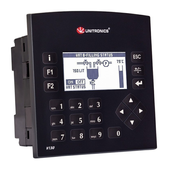
Vision™PLC+HMI
V130-33-RA22/V130-J-RA22
V350-35-RA22/V350-J-RA22
V430-J-RA22
V130-33-TRA22/V130-J-TRA22
V350-35-TRA22/V350-J-TRA22
V430-J-TRA22
General Description
The products listed above are micro-PLC+HMIs, rugged programmable logic controllers that comprise
built-in operating panels.
Detailed Installation Guides containing the I/O wiring diagrams for these models, technical specifications,
and additional documentation are located in the Technical Library in the Unitronics website:
https://unitronicsplc.com/support-technical-library/
Item
On-board I/O
Screen
Keypad
Function Keys
Com Port, Built-in
RS232/485
USB device,
mini-B
Com Ports, separate
order, user-installed
* V430J/V350/V350J comprises both RS232/485 and USB ports; note that only one channel may be used at a time.
Standard Kit Contents
Item
Controller
Terminal Blocks
Battery (installed)
Slides
(2 sets of key labels)
Mounting Brackets
Rubber Seal
Unitronics
User Guide
▪
12 Digital Inputs, including 1 HSC/Shaft-encoder Inputs,
2 Analog, 2 PT100/TC inputs
▪
8 Relay Outputs
▪
12 Digital Inputs, including 1 HSC/Shaft-encoder Inputs,
2 Analog Inputs, 2 PT100/TC inputs
▪
4 Relay Outputs
▪
4 high-speed npn Transistor Outputs
V130-RA22
V130-TRA22
V130J-RA22
V130J-TRA22
2.4"
Yes
None
Yes
None
None
The user may install a CANbus port (V100-17-CAN), and one of the following:
•
RS232/RS485 port (V100-17-RS4/V100-17-RS4X)
•
Ethernet (V100-17-ET2)
•
Profibus Slave (V100-17-PB1)
V130-RA22
V130-TRA22
V130J-RA22
V130J-TRA22
None
▪
2 Analog Outputs
▪
2 Analog Outputs
V350-RA22
V350J-RA22
Model Dependent
3.5" Color Touch
Yes
Yes*
Yes*
V350-RA22
V350J-RA22
Yes
Yes
Yes
Yes (2 parts)
Yes
V350-TRA22
V430J-RA22
V350J-TRA22
V430J-TRA22
4.3" Color Touch
None
Yes
Yes*
Yes*
V350-TRA22
V430J-RA22
V350J-TRA22
V430J-TRA22
Yes
None
Yes (4 parts)
Yes*
Yes*
1
Advertisement


Need help?
Do you have a question about the Vision V130-J Series and is the answer not in the manual?
Questions and answers