Unitronics Vision V130-33-R34 Installation Manual
22 pnp/npn digital, including 2 analog, 3 hsc/shaftencoder inputs, 12 relay outputs
Hide thumbs
Also See for Vision V130-33-R34:
- Installation manual (12 pages) ,
- User manual (26 pages) ,
- User manual (23 pages)
Table of Contents
Advertisement
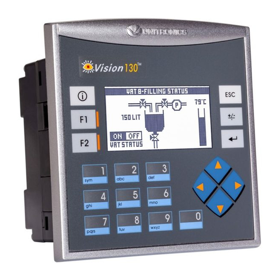
Vision™ OPLC™
This guide provides basic information for Unitronics' controller model V130-33-R34.
General Description
V130 OPLCs are micro-OPLCs, rugged programmable logic controllers that comprise:
On-board I/O configuration
Built-in operating panel containing an LCD and a keypad
Communications
I/O Options
Information Mode
Programming
Software,
& Utilities
Data Tables
Additional product documentation is in the Technical Library, located at www.unitronics.com, and on
the Unitronics' Setup CD.
Technical support is available at the site, and from support@unitronics.com.
Unitronics
1 built-in serial port: RS232/RS485
Optional: the user may order and install
one or both of the following modules:
- RS232/RS485/Ethernet
- CANbus
Communication Function Blocks include:
SMS, GPRS, MODBUS serial/IP. Protocol
FB enables PLC to communicate with
almost any external device, via serial or
Ethernet communications
V130 supports digital, high-speed, analog,
and temperature measurement I/Os via:
On-board I/O configuration
Model-dependent
I/O Expansion Modules
Via adaptor, use up to 8 I/O Expansion
Modules, add up to 128 additional I/Os
This mode enables you to:
View & Edit operand values, COM port settings, RTC and screen
contrast/brightness settings
Stop, initialize, and reset the PLC
To enter Information Mode, press the <i> button for several seconds.
The Unitronics Setup CD contains VisiLogic software and other utilities
VisiLogic
Easily configure hardware and write both HMI and Ladder control
applications; the Function Block library simplifies complex tasks
such as PID. Write your application, and then download it to the
controller via the programming cable included in the kit.
Utilities
Includes UniOPC server, Remote Access for remote programming
and diagnostics, and DataXport for run-time data logging.
To learn how to use and program the controller, as well as use utilities such
as Remote Access, refer to the VisiLogic Help system.
120K dynamic data (recipe parameters, datalogs, etc.),
192K fixed data (read-only data, ingredient names, etc)
V130-33-R34 Installation Guide
22 pnp/npn Digital, including 2 Analog, 3 HSC/Shaft-
encoder Inputs, 12 Relay Outputs
1
Advertisement
Table of Contents

Subscribe to Our Youtube Channel
Related Manuals for Unitronics Vision V130-33-R34


Summary of Contents for Unitronics Vision V130-33-R34
- Page 1 120K dynamic data (recipe parameters, datalogs, etc.), 192K fixed data (read-only data, ingredient names, etc) Additional product documentation is in the Technical Library, located at www.unitronics.com, and on the Unitronics’ Setup CD. Technical support is available at the site, and from support@unitronics.com.
-
Page 2: Danger Symbols
All examples and diagrams are intended to aid understanding, and do not guarantee operation. Unitronics accepts no responsibility for actual use of this product based on these examples. Please dispose of this product according to local and national standards and regulations. -
Page 3: Mounting Dimensions
4. Tighten the bracket screws against the panel. Hold the bracket securely against the unit while tightening the screw. 5. When properly mounted, the controller is squarely situated in the panel cut-out as shown in the figure to the right. Unitronics... -
Page 4: Din Rail Mounting
Input or output cables should not be run through the same multi-core cable or share the same wire. Allow for voltage drop and noise interference with input lines used over an extended distance. Use wire that is properly sized for the load. The controller and I/O signals must be connected to the same 0V signal. Unitronics... - Page 5 (sink) pnp (source)* Inputs 14/15: Set as Digital or Analog Set to JP1 (Input 14) JP2 (Input 15) Digital* Analog Analog Inputs AN0/AN1: Set Type Set to JP5 (AN0) JP4 (AN1) Voltage Current* *Default settings I/O Wiring I/O Configuration Unitronics...
- Page 6 V130-33-R34 Installation Guide Input wiring npn (sink) Input wiring pnp (source) HSC input wiring, npn (sink) HSC input wiring, pnp (source) Shaft-encoder Analog input wiring, current (2 wire) Analog input wiring, current (3-wire) Analog input wiring, current (4 wire) Unitronics...
-
Page 7: Power Supply
Double-check all wiring before turning on the power supply. Do not connect either the ‘Neutral or ‘Line’ signal of the 110/220VAC to device’s 0V pin. In the event of voltage fluctuations or non-conformity to voltage power supply specifications, connect the device to a regulated power supply. Unitronics... -
Page 8: Communication Port
B signal (-) *Standard programming cables do not provide connection points for pins 1 and 6. **When a port is adapted to RS485, Pin 1 (DTR) is used for signal A, and Pin 6 (DSR) signal is used for signal B. Unitronics... -
Page 9: Opening The Controller
2. The back cover of the controller comprises 4 screws, located in the corners. Remove the screws, and pull off the back cover. Changing I/O settings 1. The I/O board of the controller is now exposed, enabling you to change I/O settings according to the jumpers shown on page 5. Unitronics... -
Page 10: Changing Communication Settings
Note that you must replace the back cover securely before powering up the controller. The information in this document reflects products at the date of printing. Unitronics reserves the right, subject to all applicable laws, at any time, at its sole discretion, and without notice, to discontinue or change the features, designs, materials and other specifications of its products, and to either permanently or temporarily withdraw any of the forgoing from the market.
Need help?
Do you have a question about the Vision V130-33-R34 and is the answer not in the manual?
Questions and answers